@johnnync21 - Stuff like you mentioned needs setup or other modules extracted from the BIOS and then edited via IFR/Hex. Then you edit the module itself in hex, and insert back into the BIOS, then program the mod BIOS with ASProgrammer.
Or some BIOS you can open in tools with a GUI and edit the settings directly, depends on the BIOS. Send me a dump of your BIOS and I will let you know if any tools with GUI can be used to edit settings, or if you have to via IFR/Hex only.
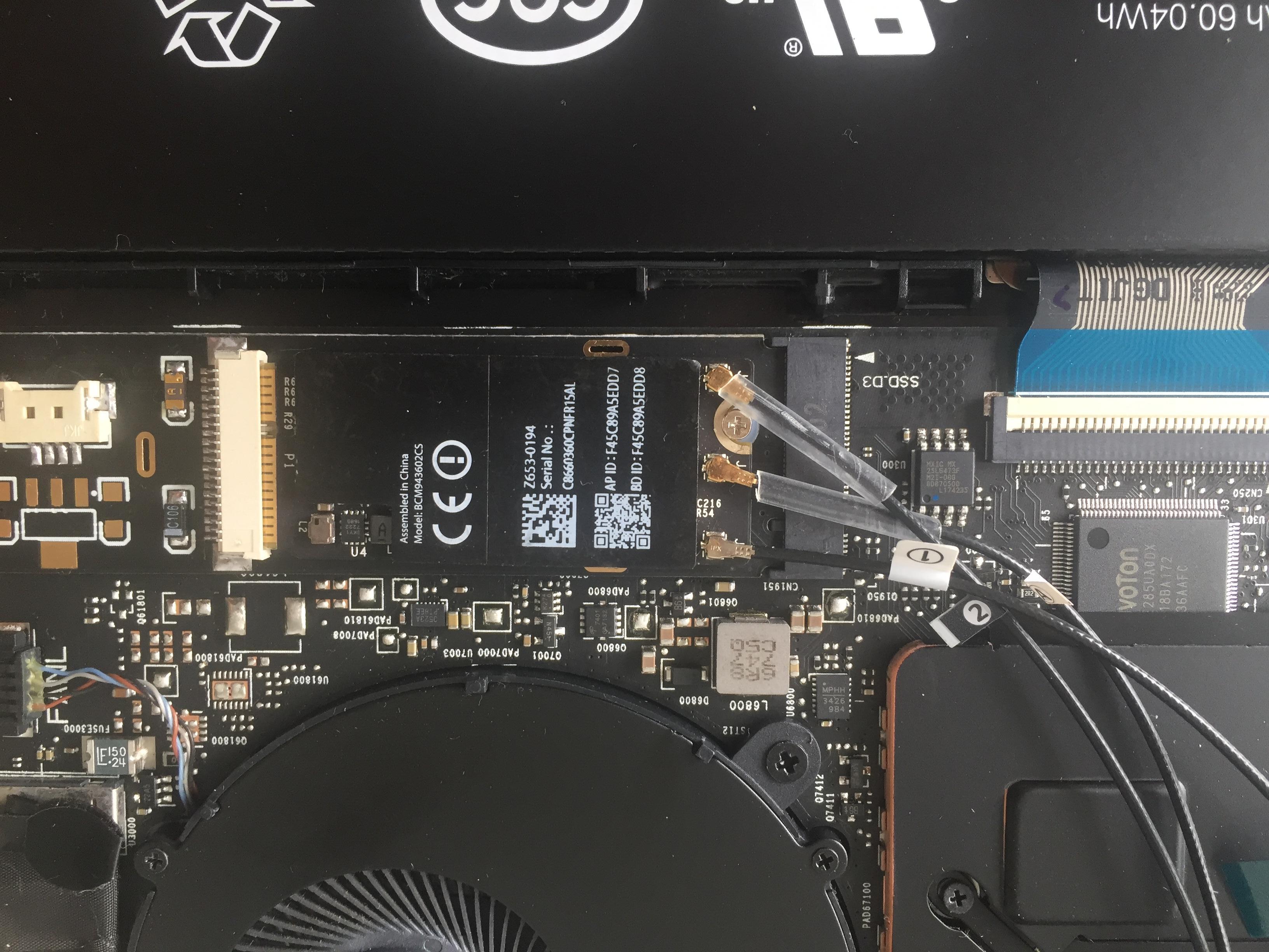
I take it you located the chip, it’s between fan and M.2 drive, right above Nuvoton chip. 
@johnnync21 - some things can be edited via EZH20, but it’s better to edit those in UEFITool anyway. I even extracted the BIOS again from the .fd file, still no luck with EXH20 
Menu settings can’t be edited in EZH20 which I assume you found out already. Most can be changed in the setup IFR or by vars as you’ve included.
Here’s how to change, via hex, edit setup file
Form: View/Configure CPU Lock Options, FormId: 0x1012 {01 86 12 10 D9 00}
One Of: CFG Lock, VarStoreInfo (VarOffset/VarName): 0x3C, VarStore: 0x3, QuestionId: 0x146, Size: 1, Min: 0x0, Max 0x1, Step: 0x0 {05 91 8A 02 8B 02 46 01 03 00 3C 00 10 10 00 01 00} << Locate this string
One Of Option: Disabled, Value (8 bit): 0x0 {09 07 04 00 00 00 00}
One Of Option: Enabled, Value (8 bit): 0x1 (default) {09 07 03 00 30 00 01} << 30 here denotes “Default” setting, move 30 to above setting instead, in same location, set 00 here in it’s place, that is all.
Same for MC Lock
One Of: MC Lock, VarStoreInfo (VarOffset/VarName): 0x126, VarStore: 0x2, QuestionId: 0x197, Size: 1, Min: 0x0, Max 0x1, Step: 0x0 {05 91 35 11 36 11 97 01 02 00 26 01 10 10 00 01 00} << Locate string
One Of Option: Disabled, Value (8 bit): 0x0 {09 07 2D 10 00 00 00}
One Of Option: Enabled, Value (8 bit): 0x1 (default) {09 07 2C 10 30 00 01} <<< Move 30 above instead
@Lost_N_BIOS and then when Can I create .bin or introduce the ifr.txt again to .fd file?
And if I want to modify others modules like wireless, I can’t use ifr extractor, because only works for setup. How Can I modify and apply changes?
This is all my modifications
Section_PE32_image_DriverSampleDxe_SetupUtility IFR.txt (1.24 MB)
@Lost_N_BIOS Okey, An earlier version(uefitool) of the file was downloaded and my backup copy could be modified. Now How I can disable PRR/FLOCKDN??
@johnnync21 - IFR text is never put back into BIOS, this is only a human readable output of the settings contained within the BIOS setup module. You have to edit the setup module itself directly via hex, like I outlined above.
If you are still unsure how to modify the setup file, give me an exact list of all settings you need changed by exact name, and what you want them changed to, and I will send you a modified setup module.
I can’t use your IFR text above, we used different IFR tools so I can’t compare, my output IFR has more info so there’s too many differences for me to easily see.
Here is same example above, but now edited before/after so you can see what I meant on how to change settings
Before-
One Of: CFG Lock, VarStoreInfo (VarOffset/VarName): 0x3C, VarStore: 0x3, QuestionId: 0x146, Size: 1, Min: 0x0, Max 0x1, Step: 0x0 {05 91 8A 02 8B 02 46 01 03 00 3C 00 10 10 00 01 00} << Locate this string via hex in setup module
One Of Option: Disabled, Value (8 bit): 0x0 {09 07 04 00 00 00 00}
One Of Option: Enabled, Value (8 bit): 0x1 (default) {09 07 03 00 30 00 01} << 30 here denotes “Default” setting, move 30 to above setting instead, in same location, set 00 here in it’s place, that is all.
After -
One Of: CFG Lock, VarStoreInfo (VarOffset/VarName): 0x3C, VarStore: 0x3, QuestionId: 0x146, Size: 1, Min: 0x0, Max 0x1, Step: 0x0 {05 91 8A 02 8B 02 46 01 03 00 3C 00 10 10 00 01 00} << Locate this string via hex in setup module
One Of Option: Disabled, Value (8 bit): 0x0 {09 07 04 00 30 00 00} <<< Now, this will be new default (And new IFR output on modified file, will move the (Default) mark to this setting instead (new “Post-edit” IFR)
One Of Option: Enabled, Value (8 bit): 0x1 (default) {09 07 03 00 00 00 01}
Not all modules will output IFR, but many more than setup. What is it you need to modify in a wireless module, and are you sure it’s the wireless module you need to modify?
Yes, to insert you need to use regular UEFITool (like 25-26 etc), the NE Alpha version is only used for extracting, hex view, informational purposes etc
FPRR/FLOCKDN removal for is covered on page one, post #4, modify BiosRegionLockDxe (GUID - BC05DC37-9DA0-4050-9728-F34DDB01E200)
Extract that GUID PE32 module as-is with UEFITool, open in hex, go to 0x05d6h location and edit line >> ba 00 80 00 00 >> To be >> ba 00 00 00 00
Then replace that PE32 back in as-is
@Lost_N_BIOS What ifr extractor do you use?
I don’t know what I have to modify to charge module wifi by nvme m.2 port
@johnnync21 - I use this one from Donovan600 Version 0.7 - http://s000.tinyupload.com/index.php?fil…680924802087821
I will look through settings and see if I see anything related to charging, it may not be possible due to hardware missing on board or traces not setup to do that?
I find wlan device variable on Setup. In Xiaomi Pro it is activated on mi air not. And others version of air like 6200u and 7200u wifi m.2 port works
@johnnync21 - What is the exact setting name, I can tell you how to change it. * Edit, I see the following
Enable Wireless Charge Support, VarStoreInfo (VarOffset/VarName): 0x5BA, VarStore: 0x1234, QuestionId: 0xAB1, Size: 1, Min: 0x0, Max 0x1, Step: 0x0 {05 91 8A 0F 8B 0F B1 0A 34 12 BA 05 10 10 00 01 00}
0x1634D8 One Of Option: Disabled, Value (8 bit): 0x0 (default) {09 07 04 00 30 00 00} << To change to enabled, move 30 here to below, as shown in above examples
0x1634DF One Of Option: Enabled, Value (8 bit): 0x1 {09 07 03 00 00 00 01}
USB Charge Battery Threshold, VarStoreInfo (VarOffset/VarName): 0xED, VarStore: 0x1234, QuestionId: 0x5, Size: 1, Min: 0xA, Max 0x1E, Step: 0x0 {05 91 1E 01 1F 01 05 00 34 12 ED 00 00 10 0A 1E 00}
0x33EE92 One Of Option: 10%, Value (8 bit): 0xA {09 07 20 01 00 00 0A}
0x33EE99 One Of Option: 20%, Value (8 bit): 0x14 {09 07 21 01 00 00 14}
0x33EEA0 One Of Option: 30%, Value (8 bit): 0x1E (default) {09 07 22 01 10 00 1E}
Do you need me to make this modification for you? If yes, what do you want the USB Charge Battery Threshold set to?
I can’t find the solution to actívate m.2 wifi. in older versions of this model it works without problems
@johnnync21 - The only “wifi” option I see in your setup is “Wifi SAR” What PCIE port is that slot using? I can change it’s topology to M2, that may fix the issue
Try checking with some other device in that slot, and use this app to get the info
Utility to view some info on PCI devices
If it’s SATA slot, see if you can find similar slot # info in HWINFO64 or AIDA64 etc, topology for SATA Slots can be set to M2 as well (Per slot)
Nvme m.2 SLOT is in port 9
That one is already set to M2 by default Maybe a certain driver needs installed, or this first setting needs changed (RST controlled or not?)
PCIe Storage Dev On Port 9, VarStoreInfo (VarOffset/VarName): 0x61D, VarStore: 0x5, QuestionId: 0x367, Size: 1, Min: 0x0, Max 0x1, Step: 0x0 {05 91 A8 09 B0 09 67 03 05 00 1D 06 10 10 00 01 00}
0x14F281 One Of Option: RST Controlled, Value (8 bit): 0x1 {09 07 A2 09 00 00 01}
0x14F288 One Of Option: Not RST Controlled, Value (8 bit): 0x0 (default) {09 07 A3 09 30 00 00}
One Of: PCI Express Root Port 9, VarStoreInfo (VarOffset/VarName): 0xC7, VarStore: 0x5, QuestionId: 0x524, Size: 1, Min: 0x0, Max 0x1, Step: 0x0 {05 91 49 06 59 06 24 05 05 00 C7 00 10 10 00 01 00}
0x153EAB Default: DefaultId: 0x0, Value (Other) {5B 85 00 00 08}
0x153ED6 One Of Option: Enabled, Value (8 bit): 0x1 (default) {09 07 03 00 30 00 01}
0x153EDD One Of Option: Disabled, Value (8 bit): 0x0 {09 07 04 00 00 00 00}
0x153EEE One Of: Topology, VarStoreInfo (VarOffset/VarName): 0x2EF, VarStore: 0x5, QuestionId: 0x525, Size: 1, Min: 0x0, Max 0x4, Step: 0x0 {05 91 66 0A 76 0A 25 05 05 00 EF 02 10 10 00 04 00}
0x153EFF Default: DefaultId: 0x0, Value (Other) {5B 85 00 00 08}
0x153F5C One Of Option: Unknown, Value (8 bit): 0x0 {09 07 77 0A 00 00 00}
0x153F63 One Of Option: x1, Value (8 bit): 0x1 {09 07 78 0A 00 00 01}
0x153F6A One Of Option: x4, Value (8 bit): 0x2 {09 07 79 0A 00 00 02}
0x153F71 One Of Option: Sata Express, Value (8 bit): 0x3 {09 07 7A 0A 00 00 03}
0x153F78 One Of Option: M2, Value (8 bit): 0x4 (default) {09 07 7B 0A 30 00 04}
All variables not working to activate other devices other than a ssd nvme
Did you NVME Mod the BIOS already?
yes…
Well you don’t need to change it away from NVME anyway, so no need to wrestle with trying other methods, unless you really want to?
Options would be H20UVE, Grub w/ setup_var, or modified grub files 2/3 with setup_var2 and setup_var3, or possibly mod BIOS to directly change the options. What method did you already try, and how exactly is it failing?
Maybe not all traces or resistors are in place for it to work for NVME same as it would for NVME, or do you think both would need the same and you already confirmed other M2 work OK?
This is going to be long: bear with me, or skip to the middle of the next post for the TL;DR.
I ran into a similar situation with a Lenovo Y700-17ISK laptop (Skylake/Sunrise Point-H, also Insyde H2O BIOS, 2015 model).
I already flashed a modified custom BIOS earlier to make the SetupUtility more interesting by exposing the advanced settings (most of which could be modified with H2OUVE anyway but that takes away all the fun from it).
Recently I had a little time to play with it some more. One annoyance about this laptop is that it’s very inconvenient to get to the EEPROM chip as it’s located on the not easily accessible side of the system board, so a lot of things have to be disassembled, numerous ZIF connectors, which are not engineered for heavy use, have to be disconnected, and finally the paper-thin system board has to be flipped upside down before any flashing is even possible. Also, every time this happens repasting has to be done as well, which feels wasteful.
So this time I decided I’d try my best to make sure the laptop won’t have to be disassembled again soon, it’s just much more convenient (and also faster) to simply flash the BIOS with FPTW. The only thing between me and this goal were 5 or so layers of protection preventing me from doing just that, but I’ve happily got around all of them:
1. Temporarily disabling ME
In one of the BIOS updates for this laptop the ME had to be reflashed as well and for that Lenovo issued something called a “fool style update” (sic! I guess it was supposed to be “full-style update”).
The update included a special utility called WinTest.exe, which can be used to temporary disable the ME for flashing. As I understand this is is equivalent to the much more pedestrian way of shorting pins 1 and 5 on the audio chip.
2. Editing the descriptor
With the ME temporarily disabled, descriptor can be edited to allow reading and writing at any time. This is however not enough for the BIOS, the “protection” of which (from the paying customer) is supposed to be the responsibility of the device manufacturer.
3. Removing BIOS Lock
This one was easy, there is a (hidden) SetupUtility option to switch it off. The setting can also be changed with H2OUVE. I’m not sure if this is even properly implemented on this laptop at all. Backflash can be enabled with another Lenovo utility (ChgBoot.exe bfen)
4. Protected Range Registers, themselves protected by
5. Flash Configuration Lockdown (FLOCKDN) flag
These two are not that straightforward. Here’s what the situation looked like originally (only quoting the relevant lines of the output to save space but I hope posting the full command line here will help someone with a similar issue as it saves the time figuring it out how to use Chipsec):
FLOCKDN:
python chipsec_util.py mmio read SPIBAR 0x4 0x4
1
[CHIPSEC] Read SPIBAR + 0x4: 0x0000E000
python chipsec_main.py -m common.spi_lock
1
2
2
[*] HSFS = 0x    E000 << Hardware Sequencing Flash Status Register (SPIBAR + 0x4)
    [15] FLOCKDN          = 1 << Flash Configuration Lock-Down
python chipsec_util.py mmio read SPIBAR 0x84 0x4
python chipsec_util.py mmio read SPIBAR 0x88 0x4
- or -
python chipsec_main.py -m common.bios_wp
1
2
3
4
5
6
7
8
9
10
11
12
2
3
4
5
6
7
8
9
10
11
12
[*] BIOS Region: Base = 0x00200000, Limit = 0x007FFFFF
SPI Protected Ranges
------------------------------------------------------------
PRx (offset) | Value    | Base     | Limit    | WP? | RP?
------------------------------------------------------------
PR0 (84)     | 87FF06C0 | 006C0000 | 007FFFFF | 1   | 0
PR1 (88)     | 857F029A | 0029A000 | 0057FFFF | 1   | 0
PR2 (8C)     | 00000000 | 00000000 | 00000000 | 0   | 0
PR3 (90)     | 00000000 | 00000000 | 00000000 | 0   | 0
PR4 (94)     | 00000000 | 00000000 | 00000000 | 0   | 0

[!] SPI protected ranges write-protect parts of BIOS region (other parts of BIOS can be modified)