@Gaudi
I would help you in a heart beat, since I was the one who “helped” you to get in this mess. It is just that I don’t have a programmer for myself. I do plan to buy one for tinkering needs, but I look for one with extended support of chips and all the accessories + adapters I can get. The problem is that the price for this complete package is quite spicy in my part of Europe.
You said that you have some soldering skills? Isn’t it better to solder a DIP8 socket and buy a DIP8 chip of 512KB? Every member here with a Marvell controller seems to have a different chip, so it is no problem in replacing your current one. Even flashing that DIP8 chip should be less expensive, since all it takes is placing the chip in the programmer. If they ask more than 10 USD to flash a DIP8 chip, then it is a rip-off, since the EZP2010 can be found at around 40 USD. If you can’t find someone to flash a detachable chip at a <10 USD price, then it is better to buy a programmer for yourself and then you can have all the tests in the world.
Just make sure to buy a DIP8 chip that it is well supported by the programmer, Macronix and Winbond being favorites.
@lordkag
We are all here to help each other. In any case, I am to blame for trying to mess with my motherboard: "if it ain’t broken, do not fix it" they say.
In any case, I have been looking at several videos on the internet and fell quite confident to be able to replace the chip itself. I bought the exact same chip (25X40BVSIG) today downtown here. I have checked and may have access to a proper soldering station, and it can even be done using a standard soldering iron.
The only thing I need now is a programmer, or someone to program the chip, and am on it.
I have searched for the DIP8 version of the chip, and it seems to be quite difficult to find one. I live in Argentina, and even buying abroad may have a lead time of as long as 3 months because of local customs.
If I am not to mess with the board and OROM versions, it is a one time fix anyway: flashing the original image via external programmer and then upgrading it to the latest version provided by ASRock. I have read that these chips can be hot swapped, so I may even boot with the new chip, and reflash the old one in the board by holding it tight into place and starting the programmer (still sounds a little bit risky as it is very small).
Am feel closer to the solution.
Thanks for the help!
Well, if you can desolder and solder yourself, then you must try to see what price they ask for flashing a removed SOIC8 chip. The service can do it in easily with an adapter and they should still charge for less than 10 USD, since you can buy a programmer in this price proximity. But why did you bought a SOIC8 chip, when you should have bought a removable chip? I thought that you plan to buy one of these with a chip like this. This way you could just pull out the chip and place it back by hand, just like your mainboard BIOS.
If you don’t plan to use a socket, then you just use your current chip, which should still work, just that the image is wrong. Either way, you still need to do a desolder for the current chip, flash the old image with a programmer, resolder the chip or the socket in place.
Out of a blue I realized that a friend was traveling to the USA and asked him if he could bring me a EEPROM programer. With a very tight timing and short notice he may be able to bring me this item (if USPS manages to deliver it on time):
http://www.ebay.com/itm/261342102111
He is returning tomorrow, so if I get the programmer I will have plenty of time to play with during the weekend.
I have also bought an identical chip W25X40BVSSIG to flash off board and replace, as I could not find locally the DIP8 encapsulation.
My initial idea is to try to flash the chip on the board, with the power supply to the MB disconnected. If that fails, I will need to replace the bad flash with the new one with the correct image on it.
I have got a question, is it possible to isolate the VCC leg of the onboard chip, boot with the spare fully connected (SOIC8 to DIP8 adapter using the DIP header), and upon boot remove the spare chip, reconnect the leg and flash the onboard chip using the Marvell tool?
@lordkag
So far I have an original 512kb Backup image, a half functional 512kb backup image and a bunch of images to use with the Marvell tool, including the allegedly functional one provided by ASRock.
Could you create a 512kb file with the data provided by ASRock just in case I need to program it using the external programmer?
Thanks
At least one of the chips should be supported by this programmer. Try first with the clamps, but it is more than likely that you will have to desolder and use that small adapter to connect your chip for flashing with the programmer.
The image provided by Asrock has already been added here. Nothing else is changed, only the image is expanded. I really do wish you good luck in this last adventure and I hope you will see the good side in all this fiasco, that you will have a better image and a new programmer for endless testing, plus the needed safety.
According to this page http://cafe.daum.net/tualatin/J11z/243
you may not need to disconnect VCC to boot from the spare chip.
I believe it’s trial and error thing…since you get the programmer, you can do anything…
Thanks Felix, this seems to be a good idea. The problem is that I do not currently have this SPI Reverse Socket. I do have several test boards at home. Do you happen to know the wiring for such an socket/adapter. It seems that every pin from the primary (soldered) chip is paired with the secondary chip, there is a 600 - 10k ohm resistor connecting Vcc and #HOLD. If so, I have no clue why the primary chip will be disabled while the secondary provides the information at boot. Has the diode shown in the pictures anything to do with this?
If I can replicate the circuit I may give it a try.
Edit: I have re read the article and the resistor is a must to the secondary flashrom to work. There is a reference of disabling the primary eeprom, but have no clue how to do that.
Final Update:
I got the flash programmer and tried to flash the chip onboard. Unfortunately I was not able to do that, so I proceeded to remove it. I was not careful enough and one of the pins got broken.
As I had bought a new chip, I flashed it with the original image and tested it. It worked!!
I did several tests, some times the IDE channel was not recognized, some other the SATA channels.
Finally I reflashed the backup and upgraded to the file provided by ASRock.
The IDE channels do not work, but the SATA port do.
I will contact ASRock for troubleshooting.
Thank you all for your help!!
Shouldn’t the IDE channel be run by Intel? Also, when switching the Marvell controller to AHCI or RAID, doesn’t this means that the IDE port is disabled, i.e. one controller to run them both? Has you board ever worked with both IDE connected and Marvell set to AHCI/RAID?
I recall you mentioned that the IDE ports malfunctioned before you flashed my images. Maybe something, possible Marvell, is failing in your board?
The IDE channel in this motherboard is controlled by Marvell, so I had no IDE channel with the controller disabled after the bad flash.
They did work, and failed after the flash from Driver-Station. So that may be confusing you.
Your images did not fix this.
I had before working both the SATA3 ports and IDE channels, as I have an IDE DVD Rom. Not that is very modern, as all the devices are now SATA, but still I tend to use it instead my Plextor PX-880SA burner while reading disks.
In any case, I am happy that I managed to fix the issue by myself.
I have contacted ASRock for the IDE thing, lets see what their response is. So far I am running the latest firmware as provided by them.
Thanks
@lordkag
I can confirm that the IDE channel (CD ROM) works if I flash the backup image (imageorig from your package Problem after flashing firmware to Marvell 9123 addon SATA3 controller (2)).
If I flash the updated image provided by ASRock (attached here Problem after flashing firmware to Marvell 9123 addon SATA3 controller (3)) I loose the IDE channel.
There must be something in the image that prevents the IDE to work properly. Perhaps it is a missing module in the firmware provided by ASRock.
Is it possible for you to check components in ASRock image as compared to the original one?
Thanks!
@Gaudi
My first impression is that Marvell broke the IDE controller and didn’t bother to test or fix it, thinking that no one will use it. This seems the reasonable conclusion based on the fact that the old image works and the new ones don’t. I have attached some images to test this:
- image_B1038 = imageorig + BIOS updated from original 1.0.0.1014 (ID 91A3) to latest 1.0.0.1038 (ID 91A3)
- image_FW1007 = imageorig + firmware updated from original 2.1.0.1410 (Jan 19 2010) to latest 2.3.0.1007 (Sep 20 2012)
Rename to image and place in bin folder. If only one fails, you have your guilty. If both fail or both work, it is an incompatibility between components. With this evidence you can write to Asrock (but post here first, to get a second opinion), apologize for the repeated inconvenience, explain how multiple tests with original and modded images have isolated the problem in component X. Since it is Marvell’s fault and the hardware is old, I doubt you will get another miracle. But who knows what Asrock might have up its sleeves.
Warning: you already had a fail with the odd combinations I made. Make sure that you are prepared for the worse, to desolder the chip again or even disable it.
Marvell Gaudi4 IDE test.rar (214 KB)
@lordkag
Thank you for your support.
I guess I am done with the testing.
- image_B1038 = imageorig + BIOS updated from original 1.0.0.1014 (ID 91A3) to latest 1.0.0.1038 (ID 91A3) Worked fine, and it is the image I am currently using.
- image_FW1007 = imageorig + firmware updated from original 2.1.0.1410 (Jan 19 2010) to latest 2.3.0.1007 (Sep 20 2012) Bricked the controller as before. I had to desolder, flash and solder again.
I do not think I will go on with the testing, as the controller it is now working and I would not risk a third desoldering as I am afraid of breaking the soldering pads.
Thanks again for your helpful support. I have learned a lot while working on the fix.
@Gaudi
It is good that you got one image to work, even though it is not the latest. But an older fully working image is better than a newer half-broken image.
I can conclude that the firmware is to blame for the faulty IDE controller. Unfortunately, I can’t pinpoint the last working one without extended testing. I actually understand your concerns, since the combination BIOS+Firmware is also important from a safety point of view. You had more failures than working images when updating only some components, so it is better to stop before destroying the chip.
I think you can write to Asrock and at least make them aware of the issues. They can’t do a thing without Marvell’s assistance, which has long ago moved to newer chips. But someone should remind them what a sloppy job they did with 91xx series.
Hello.
I’m also trying to flash my Marvel chipset. 88SE9128-NAA2
I’ve tried with the latest firmware from driver-station, but I have the same problem that some users, it doesn’t recognize the chipset.
Could you also post the proper image file and/or parameters for my case, please?
I’ve tried from a USB with FreeDOS and also with MSDOS, I don’t get any error, it just execute the command but doesn’t upgrade anything.
My motherboard is a Gygabyte ga-x58-ud3r with BIOS F8A.
Thank you.
@ skan:
Welcome at Win-RAID Forum!
Since I cannot help you myself, I hope, that you will get support by lordkag or someone else.
Regards
Fernando
@skan
I have assembled an image for your board, but we need to go through some details:
- messing with Marvell firmware on a mainboard is rather risky, since the chip is soldered to the board.
- you might be lucky, since the firmware is inside the BIOS (AWARD) and your board has Dual-BIOS. I think you might even get away with a wrong firmware, but don’t place all your hopes on this.
- The ID inside firmware and OROM is 91A3 for IDE/AHCI/RAID compatibility, but there could be a second firmware in a separate chip.
So I need extra info to build one final image:
- Run the Marvell firmware flasher from DOS and type “go -r -y”, then upload the image IMAG_RB.BIN
- Install Marvell RAID Utility - MRU. You can find it here or here or google.
- Disconnect any drive from Marvell ports. This is to prevent data loss during following tests. You can connect a spare drive.
- Swith Marvell controller to IDE and hit Ctrl+M during boot to access Marvell Boot screen, then take a photo of that sceen. It should look like this, with ID and version.
- Start Device Manager and post the ID of Marvell controller. It should look like this, but with different IDs, of course.
- Try to start MRU and post a screenshot of the adapter window. It should look like this, but containing the entire page. If MRU doesn’t start in IDE/AHCI, ignore this step.
- Repeat the above 3 steps with AHCI and RAID.
- Put the images in 3 separate folders - IDE, AHCI, RAID. Each folder must contain photos/screenshots from Marvell Boot screen (Ctrl+M), Windows Device Manager and Marvell RAID Utility. Then add IMAG_RB.BIN and upload them as zip.
I don’t really need all this info, I can easily build an image with 91A3 ID. But since I have the chance to test some things, why not take advantage?
Hello.
My trials to flash the latest station-drivers firmware didn’t work, I think the chipset couldn’t be detected.
Then I surfed on many forums and finally I dared to try…
I couldn’t wait and I flashed the file f16t300p8552n2_gJEpIsjY.rar, I think I found it at this forum.
My previous firmware was:
vendor 1B4B, Devide ID 9128, revision B1, firmware 2.1.0.1502
Now I don’t know about the new versions installed because I don’t know what tool I can use to inspect the image file, and I’m not able any more of entering into the BIOS submenu that shows this information. I think the image is 1.0.0.1813 (showed when flashed) but I don’t know if this is the firmware, autoload, bios or what.
( I started with a “go -r” but itstead of taking the original image it started to erase, I don’t know why)
I would like to change it again, maybe with the file f16t300p6356n2.zip or something newer?
This one, besides containing a image file it also contains another file called IMAG_RB.BIN
what is it for?
On the meantime, while I’m wainting to know if I should use the second firmware or something else I must say that at least my bencharmks are better.
Results with the original firmware (and with bypass option at Bios that also improved the results)
Results with the new BIOS. Just slightly better, still far from theoretical value of the 840 EVO SSD.
And if anybody is interested, the results for the drive connected to the Intel Sata II port instead.
I’ve only tried the drive as a secondary drive, not booting from it, so I don’t know if it’s stable. Anyway I don’t like the fact that you can’t change the RADI chipset settings from the BIOS as earlier.
regards
f16t300p8552n2_gJEpIsjY.rar (210 KB)
f16t300p6356n2.zip (348 KB)
@skan
Don’t use the name given by the server, you just make me lose more time on splitting the image and check the version of the components. Just post a link to the message from which you downloaded.
You tried to flash station-drivers firmware and failed. Do you remember with what error? Was it “no supported chip detected” or just ID mismatch? Then you flashed f16t300p8552n2_gJEpIsjY.rar taken from this post, which was meant for external card U3S6R0 with 9123 controller. The file f16t300p6356n2.zip is from this post and is for external card U3S6R1 with 9120 controller. Not much of a difference besides autoload and ID in BIOS. The file IMAG_RB was just a dump taken with “go -r -y” to check if the image was properly written.
Those images won’t work for your mainboard because of different autoload, which is important for the boot sequence, thus missing the Marvell boot screen and Marvell booting ability. The ID in BIOS might make a difference, but my guess is that the ID is flexible enough for IDE/AHCI/RAID switching. When you say you had “vendor 1B4B, Devide ID 9128, revision B1, firmware 2.1.0.1502”, from where is this taken? In the mainboard BIOS you have ID 91A3 with firmware 2.1.0.1113. That is why I asked for the image taken with “go -r -y”, to see what firmware is in use. Also take a backup of your mainboard BIOS, to see if the firmware inside has changed.
I need you to do as many steps from the previous message and post images + IMAG_RB.BIN + main BIOS backup. Read each line, run each test and post which one didn’t worked. Do it 3 times, for IDE, AHCI, RAID. For switching between IDE/AHCI/RAID use BIOS settings, taken from manual:
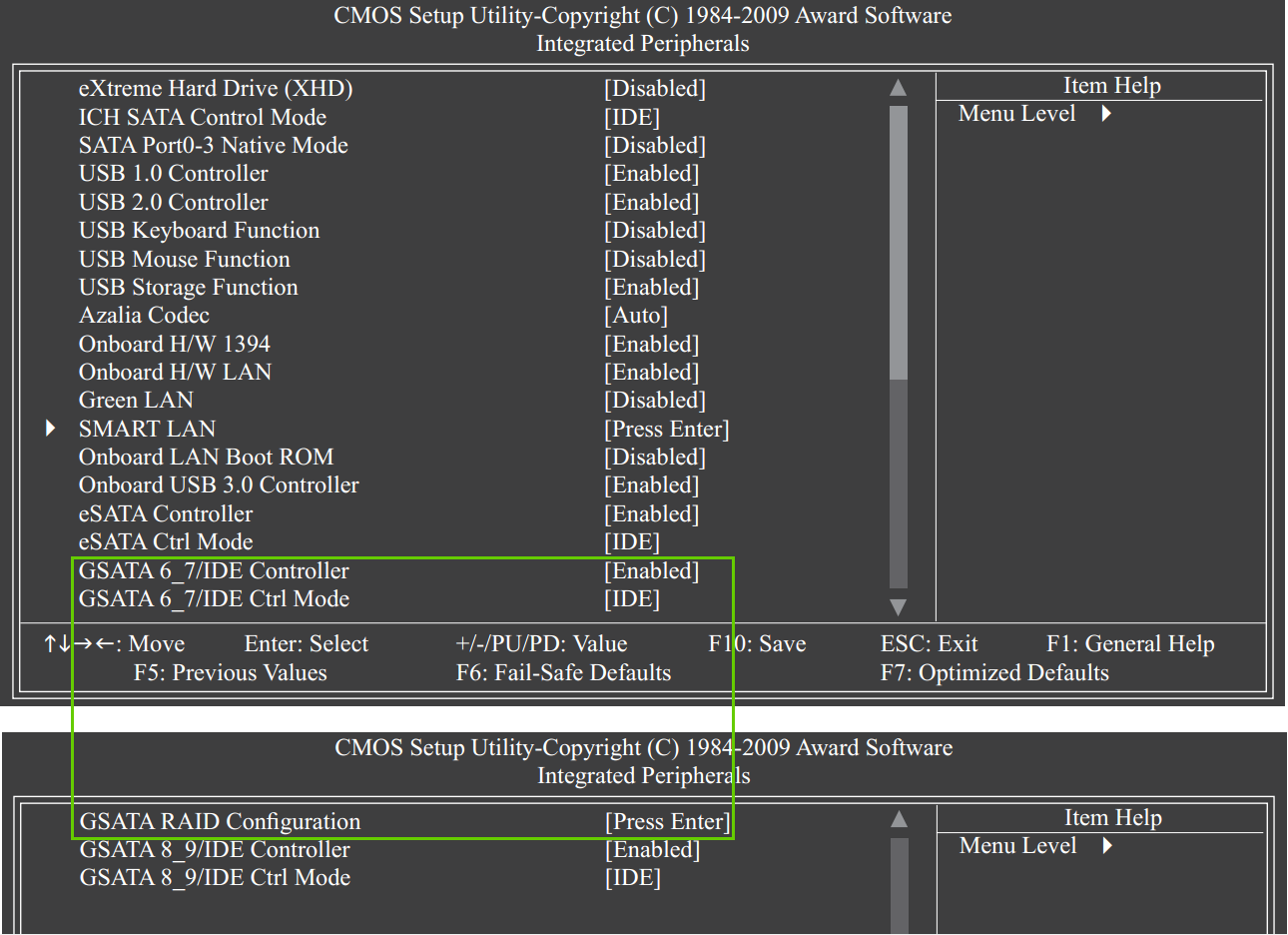
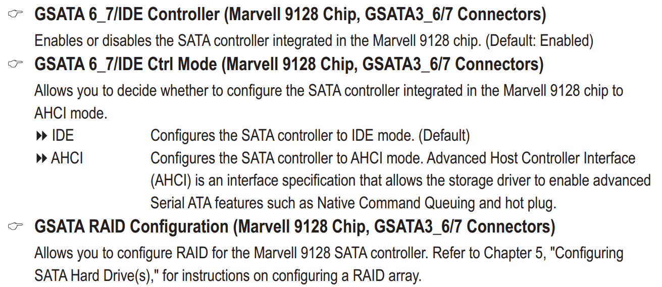
For reading ID and firmware use Marvell RAID Utility. It should show the same info as Ctrl+M. Install different versions if one doesn’t work.
This is the last time I’m asking for a proper feedback. If you don’t post the relevant information, then I’m just going to upload the image with ID 91A3, which mirrors the firmware from mainboard BIOS. Or I might not post it at all.
Hello. @lordkag
When I first tried to flash the firmware from station-drivers I didn’t get any error, the command just finished without error and without any message.
I’m sorry about the names of the files, I downloaded many files some weeks ago and unfortunatelly I mixed them, I don’t know where they where from.
I’ve checked my download history and it’s from here:
http://files.homepagemodules.de/b602300/…n2_gJEpIsjY.rar
But I guess this is not helpful.
From the BIOS before flashing, inside the section GSATA3 Controller.
I think this is not possible anymore because I flashed the new one and I guess that overwrites the old one.
Now it’s not possible.
Using Ctrl-M doesn’t do anything (before it worked), and from the BIOS if I try to enter the GSATA option the BIOS hangs completely.
At the moment I have the BIOS configured as bypass the firmware and read it onchip and I think my computer now it’s much more slow.
Please tell me what data you need and how to get them.
The result of "go -r -y" now, with the new firmware is:
I see that it says "erasing" and "flashing" but it complains about the ID mismatch"
I’m using a USB with FreeDos because another DOS iso didn’t work. And I see the batch file can’t set the proper system variables.
Do you advise any other booting method?
or if I do it directly with mvf_mag.exe do you know what parameters to use?
Best regards and thank you very much