Digging into this and @make-it-easy 's thread, I am at this point. I do not seem to have the required folder, or I need to change something to reveal it.
Digging into this and @make-it-easy 's thread, I am at this point. I do not seem to have the required folder, or I need to change something to reveal it.
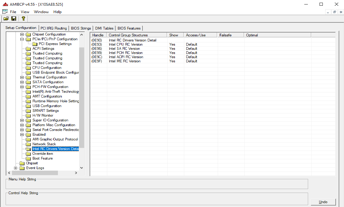
Yes… you maybe out of luck in this bios/model, ill not analyse the bios but using IFRextractor or searching “related” terms/strings in AMIBCP, if not found then its not even hidden, simply weren’t implemented.
https://www.supermicro.com/en/products/motherboard/X10SAE
Im afraid you wont get BI from this motherboard/chipset.
EDIT: The “just add” doesnt exist… there was some similar operations but was not adding new/non existing, was more like a replace feature, death end.
The crossflashing… ill step out now if you dont mind.
No GPU… ok, then you need a PCIe M.2 adapter with BI controller on it, not depending of the motherboard chipset OR 2 adapters on both x16 slots (will work @ x8), period.
Not the best solution… but you can now already find some x1 adapters… for storage can be a solution (less performance… ), leaving the main boot drive in the x16 slots.
Could I add such a feature, or perhaps cross flash a different X10 BIOS? This is for my file server, so the lone x16 slot is not needed for a GPU.
The cost of a BI quad card doesn’t make sense compared to just buying another MB. This is all for my file server, so I will just replace the quad card with two single cards running at x8
Thank you for looking into it for me
As a side note, this $35 card combined with a Samsung 970EVO Plus maxed out at (R)3500+mb/(W)3200+mb for me.
https://www.amazon.com/dp/B09BJ163KY
Hello guys!
Someone have try to bifurcate an EVGA X99 MB? I’ve tried by myself but unfortunately, I’ve only success to split in 4x4x4x4x the 1st port of my X99 FTW-K.
My target is to bifurcate in 2 the 6th port which is in 8x.
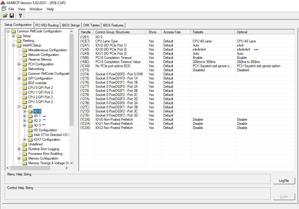
I’ve tried all combinations (12 in total) directly with AMIBCP 5.02.0031, but no way, the only working setup is with IIO 0 /IOU1. Maybe it’s due to the last port is shared with an the M2 port of the board.
FYI, here’s the layout of the MB from the documentation:
PCI-E Lane Distribution (40 Lane Processor)
PE1 – x16 (x8 if PE3 is used)
PE2 – x1 (Gen2, lane is pulled from PCH)
PE3 – x8
PE4 – x8
PE5 – x16 (x8 if PE4 is used)
PE6 – x8 (Disabled is M.2 is used)
I’m using a 40 lanes CPU (6950x) and the last availlable version of the Bios (0208).
There’s also something strange, it seem my bandwith is caped to 5GT/s when bifurcation is on.
Does someone have an idea on how bifurcate the 6th port, please?
Regards from France ![]()
Was wondering if any one has a copy of the Intel Datasheet for the Broadwell-E X99A platform. Looking to find registers to manipulate to force a pci-e x16 slot to operate at x8 such that hopefully my m.2 will have the lanes it needs to bump up from pch x2 operation to full pci-e x4 operation when all the pci-e slots are occupied with solid state drives for example. So not looking to bifurcate any more. Just redistribute cpu lanes.
Thanks
Unfortunately that’s not always the case…not even for Asrock Rack “pro” server board I have, based on Xeon D-1541
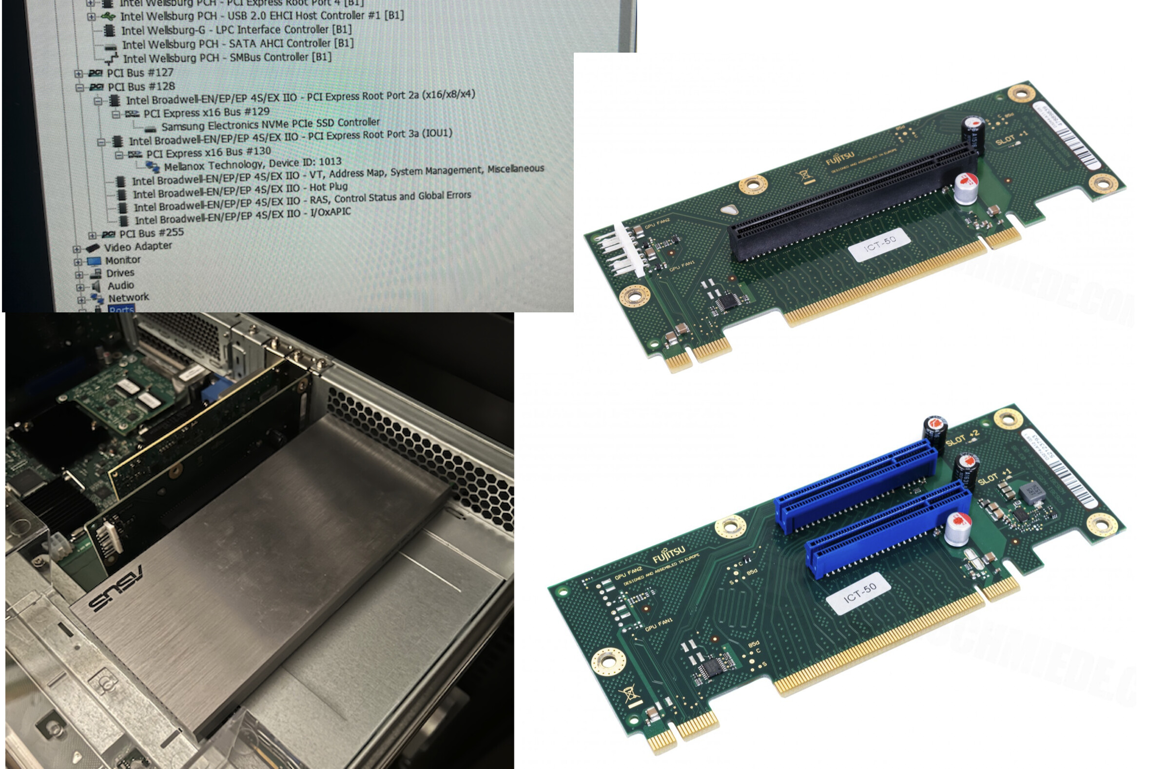
I am just trying this on a Fujitsu RX2540 M2 without luck ![]()
“IntelRCSetup” is hidden but also the UEFI variable does not change anything.
I tried all combinations and slots already, also without the GPU riser adapter. Only one M.2 SSD will be detected.
OneOf Prompt: "IOU0 (IIO PCIe Port 2)", Help: "Selects PCIe port Bifurcation for selected slot(s)", QuestionFlags: 0x10, QuestionId: 582, VarStoreId: 1, VarStoreOffset: 0x531, Flags: 0x10, MinMaxData: [0, 255, 0]
					OneOfOption Option: "x4x4x4x4" Value: 0
					OneOfOption Option: "x4x4x8" Value: 1
					OneOfOption Option: "x8x4x4" Value: 2
					OneOfOption Option: "x8x8" Value: 3
					OneOfOption Option: "x16" Value: 4
					OneOfOption Option: "Auto" Value: 255
				End
But it must be supported somehow because Fujitsu offers PCIe x16 and dual PCIe x8 risers.
You may need manually hex edit of AMIsetup modules, read a bit: msi z490 unify bios mod - BIOS/UEFI Modding / BIOS Modding Guides and Problems - Win-Raid Forum (level1techs.com)
3 topics to read
https://winraid.level1techs.com/t/guide-adding-bifurcation-support-to-asus-x79-uefi-bios
https://winraid.level1techs.com/t/guide-how-to-bifurcate-a-pci-e-slot
https://winraid.level1techs.com/t/guide-pcie-bifurcation-mapping-iio-iou-to-pcie-slot
Thanks! I already checked those guides.
Flashing a modified bios will be the next try.
But why is not working via the variables only? (Of course it will not survive a CMOS reset, but it should be fine for testing)
One thing to mention: Changing the hole slot to a different link width like x8 works fine via ru.efi and is shown in hwinfo but not the bifurcation stuff. So this modification method is working in general!
In case anyone with x99 Asus Rampage 5 Extreme still wish to know (I was not able to find any modded bios over the net to enable bifurcation)
I did this (after reading here, special thanks to davidm71 and Mir_Computers) just because R5E has dual bios chips, so almost no risk to bricking the board.
Took a previously modded 4101 bios (cpu microcode removed to allow all core turbo boast for xeon v3), used “AMIBCP 5.02.0031” to open the “R5E.CAP” file, navigated to “IntelRCSetup → IIO → IIO 0” and changed IOU0’s Failsafe and Optimal value to “x4x4x4x4”.
(This will bifurcate the 2nd Red PCIE x16)
After saving the file, use a HexEditor (I used HxD Hex Editor version 2.5) to copy the first row (first 16 hex) of the original official CAP file and paste over the modded 4101 bios’s first row.
Finally, I flashed using the usb bios flashback method.
my 4 different nvme drives now appear using the 2nd slot.
Hello CharlesLim,
I tried this with Asus Rampage 5 Extreme board but didn’t work. I have set this on all the IIO’s and still doesn’t work. Only one NVME card shows up. I have a 40 Lane CPU (E5-2630L v3).
I am using this card so i wonder if this is the issue.
Can you please help me? I am using x4x4x4x4 but i only have 2 x NVME slots. I can use x4x4x8 which i did try and doesn’t work either.
Can you confirm i should be plugging this into slot number 4 as per diagram here.
hi ronald32,
yes, the red slot I used, which I referred to as 2nd Red PCIE x16, is indeed the 4th slot of the diagram.
Reading from your post, it does appear to be the same modification I did. For reference, the cpu I used was E5-2630 v3 (not the low power one).
Is it possible that the x16 slot is expecting to get signals from all x4x4x4x4 path? As my adapter actually populates all x16 paths of the slot.
Hello CharlesLim,
Thanks for the response. I got it working by removing the raid controller of the from slot number 2 which is PCIe x8 slot. If i plug the raid card in slot two i am only able to see one NVME drive. I am not sure if it is sharing the bandwidth across the slot.
When i connect my NVME drive using this card and i also populate the existing M.2 slot on the motherboard. I have a total of 3 x NVME drives.
The CPU is differently a 40 lane and shouldn’t affect the second slot in anyway. At the moment i have slot 1 populated with GPU, Slot 4 populated with the NVME card and slot 6 populated with raid card which is running at x4 speed since it shares the same bus with the onboard M.2 NVME drive.
What do you think the issue is with slot number 2? All the slots are referenced in the motherboard picture i posted.
hi ronald32,
glad to hear that at least the NVME card is working when you use Slot 4.
I think to use your NVME card on Slot 2, which is X8, you would need to do the same bios modification but on IOU2. Change IOU2 (IIO PCIe Port 1) to “x4x4”. Just a guess on my part.
I don’t want to use slot 2 for NVME but use it for raid controller card. When i populate the slot my raid card shows up but the slot 4 only shows 1 NVME drive. The second drive disappears from the BIOS.
It’s like slot 2 disables the speed on slot 4 to be x4 only. Shouldn’t a 40 lane CPU have all the PCI lanes available? or is it not the case on this board?
I figured it out. I am using more then 40 lanes that’s why the other slot get’s disabled. I understand why it’s not working now.
Thanks for your help.
out of curiosity.
how many slots are you using? referring to the diagram, there are 6 slots. Only the 4 red slots (1,2,4,6) go to cpu directly. Under 4-way SLI, it will become x16, x8,x8, x8; and Slot 6 shares with the M.2.
If you use Slot 1 for GPU, Slot 2 for raid card, Slot 4 for nvme card, that is x16, x8 and x8. And since you use M.2, Slot 6 only get x4, if you are using Slot 6.
So when you mentioned “slot 4” in your earlier post, you were referring to Slot 6 is it?
(my curiosity is that when engaged 4-way SLI configuration, whether the BIOS mod of x4x4x4x4 still works but now just became x4x4 only due to limitation of pcie lanes)
Yes i was using all PCI lanes to the cpu. Slot 1 is GPU, Slot 2 is Raid card, Slot 4 is NVME.
GPU uses x16
Raid card uses x8
NVME uses x16.
I populated M.2 slot which uses x4 and now i am exceeding the PCI Lanes because it’s more then 40. I will get 4 x NVME drive adaptor that will fix the issue since i split the 4th PCI lane to x4x4x4x4 rather then x4x4x8. I want to have 4 x NVME drive so the end goal is fine.