[Guide] How to Use a CH341A SPI Programmer/Flasher (with Pictures!)

Lost_N_Bios, yes, you are right, I shouldn’t do that. My iMac is iMac mid 2011, 21.5, core i5. Thank you for your time

Hi All,
I can’t get flashrom to detect the chip using a Linux bootable usb…nor can I get the crappy windows AsProgrammer software to detect a chip.
I modded the Ch341a (Black) that I have to have 3.3V (measured @ 2.9V) instead of the 5V. I also cut the trace to pin 1 and tied it to ground, as the replacement chip I have is active low CS on that pin.
I’ve found /dev/bus/usb/ permissions commands on other forums to get around errors concerning flashrom usb access permissions. I’m using the command below to try and read the chip.

sudo flashrom --programmer ch341a_spi -r .bin

The only time I see the “Run” LED active on the programmer is I try to read or write to the chip using the AsProgammer in windows.
This happens regardless of whether or not I have a chip even connected to 25x SPI ports.

Does anyone have any thoughts?
Super frustrated

Hi

I have a bricked motherboard Gigabyte z170 Gaming 7 with Dual Bios chipsets MXIC MX25L12873F M2I-10G.
After of a wrong Intel ME firmware upadate I have continues boot loop (monitor never wake up-always off) with the last post (before loop) motherboard error code “b2”.

I try everything to backup main bios from back up but never worked out.

Before i try anything with programmer …If i manage to solder Backup bios chip in Main bios chip position it will boot up?

I have order BIOS USB Programmer CH341A (https://www.ebay.co.uk/itm/EEPROM-BIOS-U…353.m2749.l2649)
Im totaly noob and i want some1 to tell me the next steps so i can have my MB back in working condition.


Please help me.

Hello,
I hope you guys can help me out.
I have a HP x360440 G1 Notebook and I think the Bios is corrupted. When I power the Laptop there is no POST. Just the fan is spinning on full Speed, no Display nothing.
It has the MX25L12873F chip on it. I ordered a CH341a to dump the BIOS so you guys can look at it.
When I try to detect it with the recommended CH341a v1.31(1.4) it gives me Chip Info FFFFFFFF.

I tied every programm in the CH341A Tools file you guys posted here. Only the CH341A v1.29 is able to read but when I try to verify it its giving me a mismatch error.

The AsProgrammer 1.4.1 can read it too but it shows only FFs so there is something wrong I guess.

Long story short can you guys give me advice or what I should try?

Thanks in advance

thank for the tutorial helped me out

I tried to follow the guide on this site here but got no reply. Maybe I posted in the wrong place (and maybe that guide should be merged here). Nevermind.

I solved the problem myself and thought I share it here in case anyone has a similar issue.

Apologies for a long post.

The Problem :
The problem with my motherboard (Z77X-UP5-TH) was that CH341A (attached to the BIOS flash chip via Clip cable) could not provide enough power to the flash chip.
The reason was obvious: when you attach the Clip cable which carries the 3.3v for the flash chip, it will also try to power up EVERYTHING else that is on the 3.3v bus on the motherboard. The result is that the voltage regulator on the CH341A is not capable and the voltage sags to 1.68v. Thus the Flash chip was never detected by the software.

The Solution :

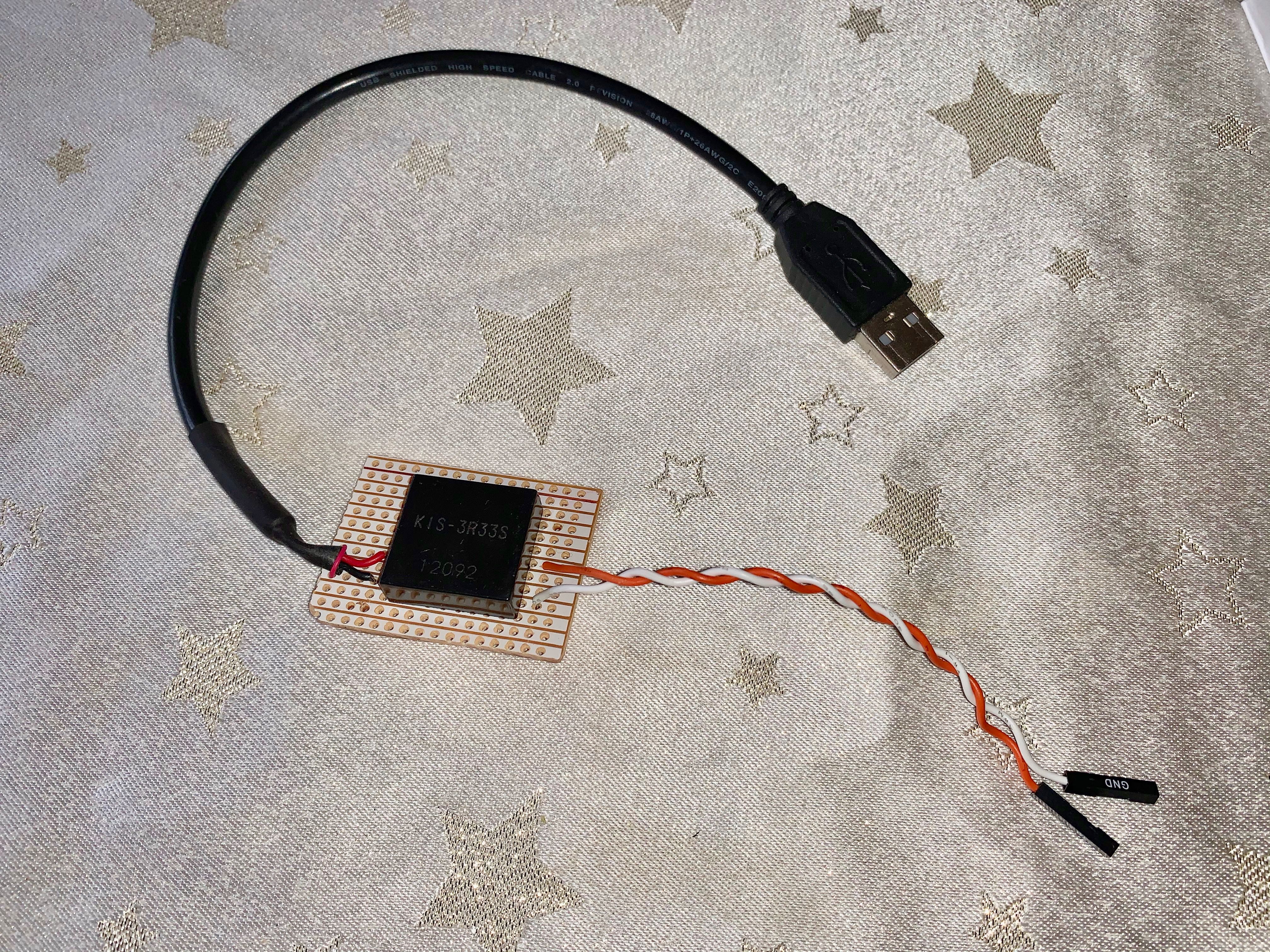
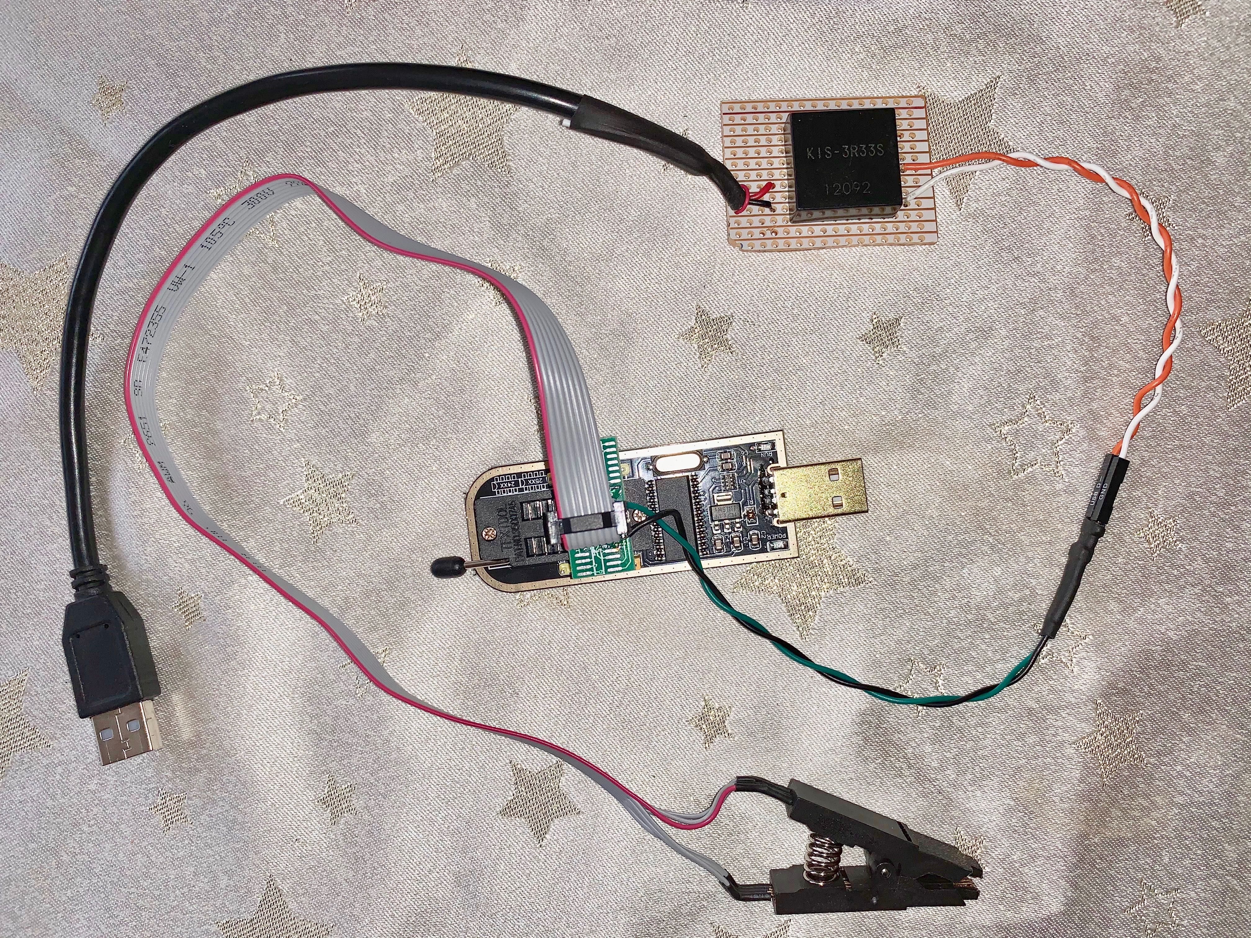
1. Provide an external 3.3v supply on the Clip Cable attached to the CH341A. I simply built a USB 5v-to-3.3v supply using a KIS-3R33S module that I happen to have in my spares (very cheap on eBay). This converter can supply around 1A of current:

IMG_1578.jpg


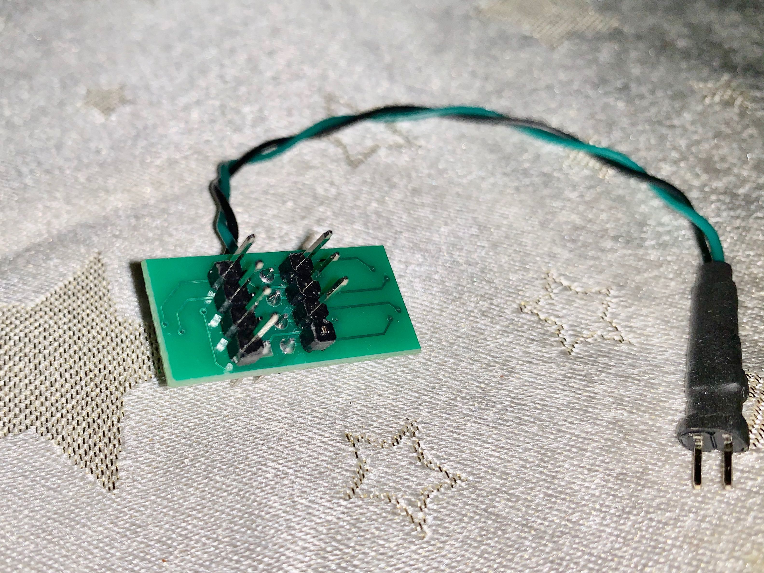
2. Cut off PIN 8 (VCC PIN) on the Clip adapter that connects to the CH341A so that 3.3v CANNOT go up the Clip cable. Then solder two wires to the adapter on PIN 4 (GND) and PIN 8 (VCC):

IMG_1580.jpg


IMG_1579.jpg


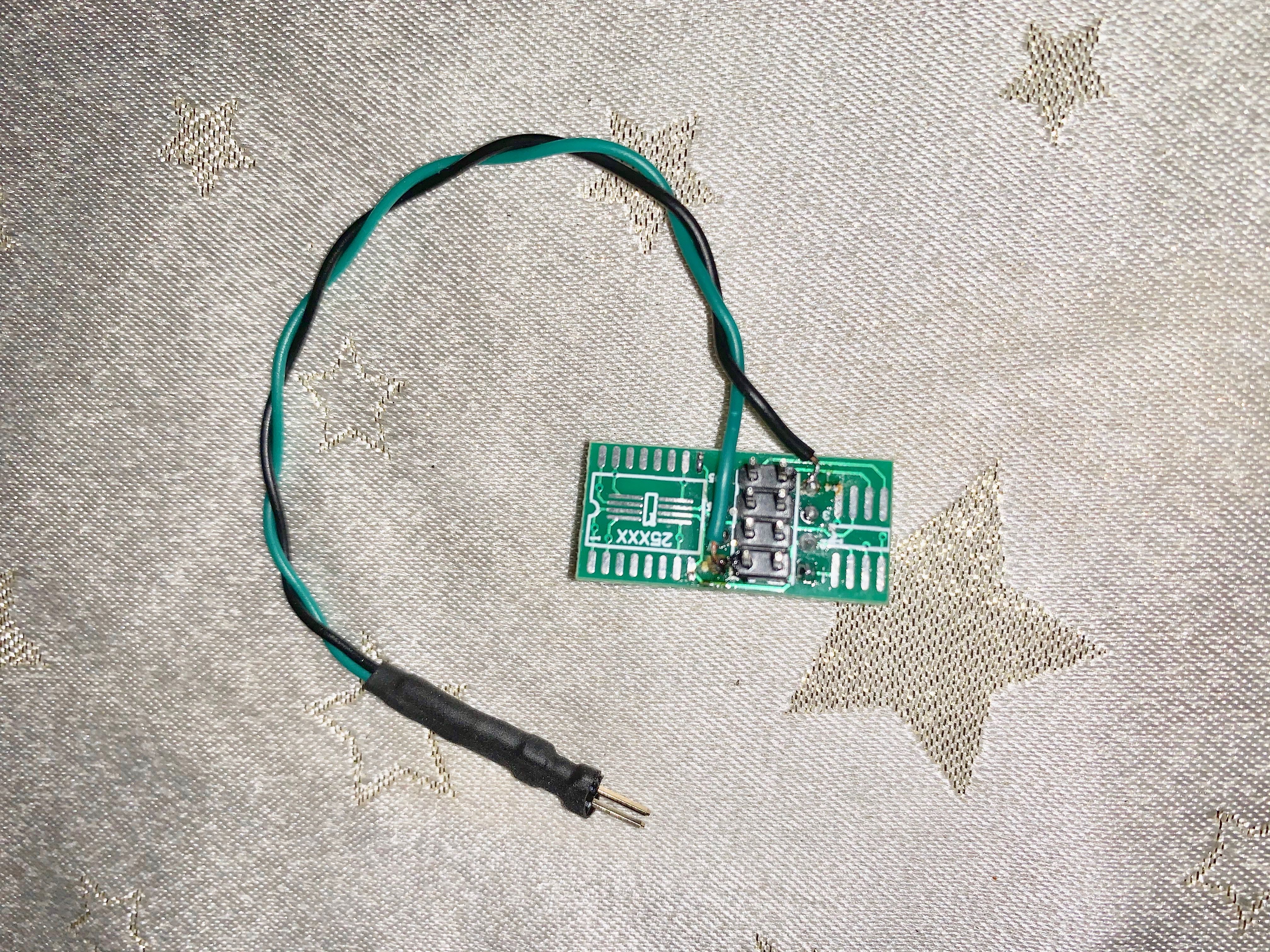
3. Attach the Clip cable to the adapter:

IMG_1581.jpg


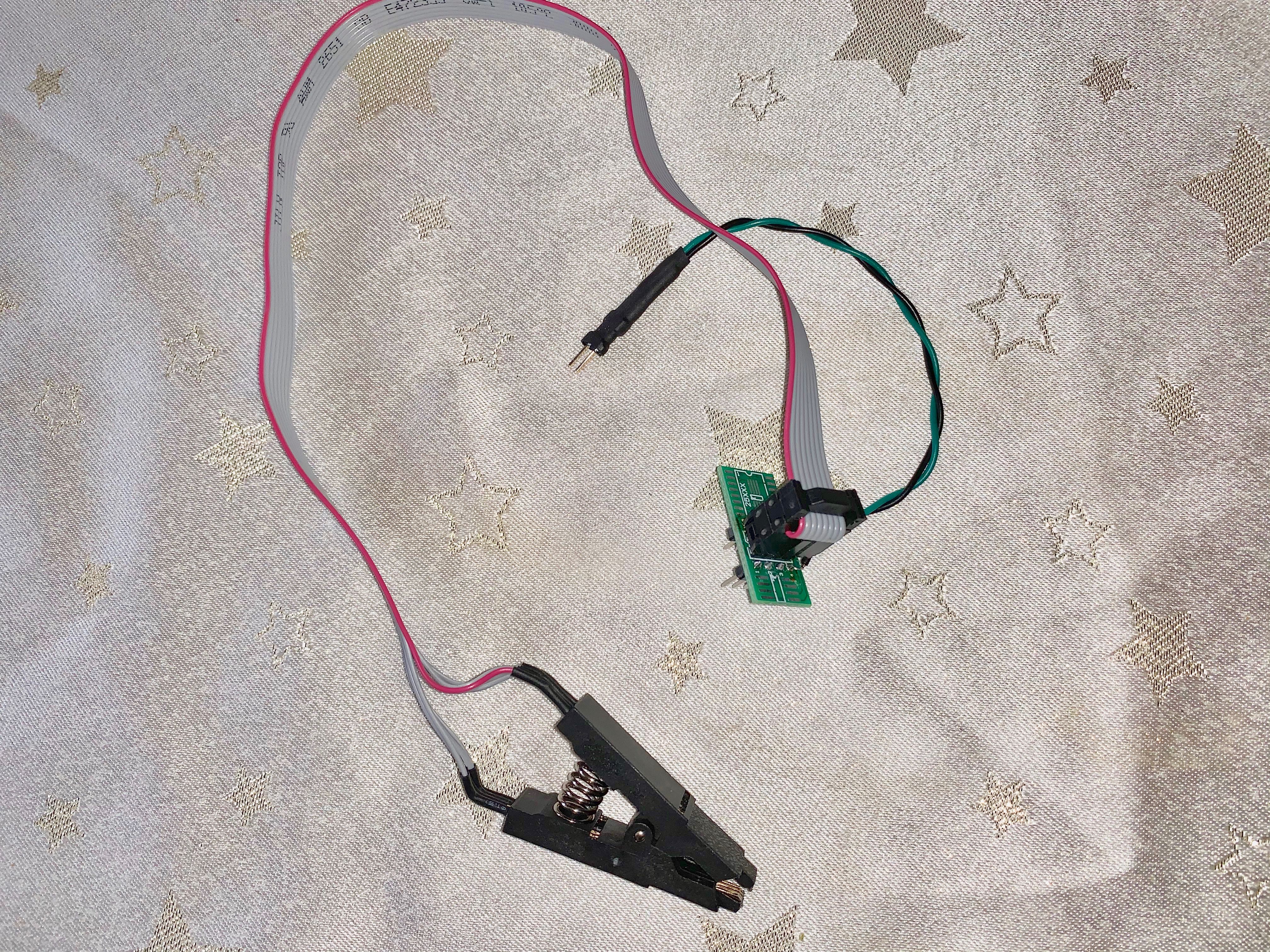
4. Attach the Clip cable + adapter and the external 3.3v supply to the CH341A:

IMG_1582.jpg


5. Plug both the CH341A and the External USB supply to a working PC.

6. Attached the Clip onto the BIOS Chip.

7. Attach the ATX PSU to the motherboard (with the BIOS chip) BUT DO NOT power on the motherboard via the case power switch (but only at the Mains supply). On my motherboard there’s board power switch with an LED which lights up to indicate ATX PSU is ready.

8. Start the CH341A software of your choice (I tried 1.29, 1.31, 1.34, Flashrom, AsProgrammer, etc) and all will now detect the BIOS chip.

I was then able to read back, erase, write and verify the Main BIOS chip with my BIOS and the also the Backup BIOS chip with Gigabyte’s stock BIOS.

I read-back the BIOS’s with different software versions and types and binary-compared them successfully.

The motherboard is now recused.

A note on the external supply: even though it is rated over 1A @ 3.3v, it does not regulate well. When not loaded, it supplies 3.26v. The voltage drops to around 2.86v when the Clip cable is connected to the motherboard BIOS chip. That voltage is within the tolerance of the BIOS chip. I measured the current drawn from the 5v USB supply it was drawing around 380mA during read/write.

Thanks for the guide. It helped me save this board.

SST 26WF016B: All programming software I own doesn’t recognize the chip? Someone who knows a chip similar to this one and known to programming software (Asprogrammer/ XGpro)?

Thanks in advance!

@Lost_N_Bios


Sorry for PMing you weeks ago. I did not read your signature.

I will tag you in a thread in which i need help with once i get my SPI dumped.


Apologies again.

Hope all is well


@Lost_N_BIOS

I have an X570 MSI Creation motherboard. Every tool I tried says I’m connected, but I get FF when I try to detect the chip and says Chip Not Detected.

I tried Googling to see what kind of chip the motherboard has but can’t find anything.

I don’t know what to do.

Edit. I CAN erase and verify the chip and if I try to Program the MSI bios.bin it gives me a write error.

Also, when I open the BIOS in the Programmer it says ‘File length beyond range which will be ignored’.

Here is the bios.bin in a .zip file.

https://drive.google.com/file/d/1kzG7eJM…iew?usp=sharing

Hi i just by ch341a black edition. Can i use flahrom to flash SIO chips. If it can how do i do that. Is there any video tutorial how to use flashrom with ch341a on windows.

Thanks

Stevedb

@Lost_N_BIOS , this might be a stupid question but I read the whole thread and didn’t find a clear answer.
I always backed up my bios region using fpt -d -bios and would now like to flash it back using the ch341a.

What is the best approach for this?
-dump full bios using ch341a
-replace bios region witch backup bios region in the full bios dump using UEFITool
-flash new full bios dump with ch341a

or is there some way to only flash the bios region with the ch341a?

Just like to be prepared before I start :slight_smile:

@snixel - Yes, that will work how you mentioned. Flashing BIOS region only with programmer could be done, but I’ve never done so don’t know the procedure to limit area it writes to certain start/end offsets but I assume some program software can do that (Maybe flashrom or ASProgrammer with script)
If you need to recover, and you know ME FW isn’t broken, dump with programmer, replace BIOS region in that file with your known good BIOS region from FPT dump using UEFITool, then program entire BIOS back with CH341 (just like you mentioned)

@Lost_N_BIOS , thanks!

ME region is untouched. I accidentally screwed up the GOP VBT in the bios region and now my laptop refuses to boot. I only flashed the bios region with FPT so only bios region is affected.
I examined the chips on the mobo and found two candidates. One is a Winbond 25Q80DVSIG, this one is probably for the EC FW as it is only 8M-bit/1M-byte.
And the other is this one:


After scraping off the red dot it appears to be a GigaDevice GD25B64C and the datasheet says 64M-bit/8M-byte, so I guess we have a winner.

Before I start, this is a notebook so I should probably disconnect the battery before I try to read it? I thought you said somewhere that the CMOS battery is not necessary or should I first just try without it and if I can’t read it, try again with battery and/or cmos battery plugged in?

The voltage range of the chip is: 2.7~3.6V, so I wont be needing a 1.8V adapter and can just clip on the SOIC8 clip directly?

Do you have any experience with these type of chips by any chance? My best bed is to start with the v1.31/1.4 version of the software?

@snixel - Yes, try without battery and PSU, then if you can’t read after several clip attempts, try with battery and PSU connected. Yes, no adapter needed since BIOS is not 1.8V

You may need to use GD25Q64 ID or EON EN25B64 - Use software 1.34, included below

If that fails, then use Colibri included in package below, or CH341 Programmer v1.1.1.32 included in package below too.
http://s000.tinyupload.com/index.php?fil…695330485827902

If those fail as well, try ASProgrammer 1.41 - https://github.com/nofeletru/UsbAsp-flash/releases/


My chip is connected on my MSI X570 Creation, I can erase the chip and verify after erasing. But when I detect the chip it says ‘Not Found’ and I get a write error in 1.34 if I try to write the BIOS anyways and before I get an error ‘BIOS size not within range, will be ignored.’

Do I need to attach a 1.8v adapter? I don’t have one but can buy one.

Edit: I tried every BIOS programmer as well, all FF’s. :frowning:

@KedarWolf - sorry, not sure what you are replying to, or why you quoted what you did? What is your BIOS chip ID? if it’s same one I said above, do those things.
I don’t know if you need 1.8V adapter, I don’t know what chip you have. * Edit - No, W25Q128FV is not 1.8V chip, you do not need adapter

Ohh! Sorry, I looked back, your chip is mentioned on previous page, and I gave you info on how to write (what software/version to use etc)
You need to use the CH341A software version I mentioned (1.18), or ASProgrammer 1.40/1.41 ONLY

I would not write MSI BIOS, send me your original BIOS dump and I will make you a BIOS to write in. If you never made a dump before you erased, then you possibly lost UUID and serial if stored in BIOS, and LAN MAC ID for ethernet too.
We can fix serial and MAC, but not UUID, at least not original, unless you have dump of BIOS from before you erased

I assume this is your board? MSI PRESTIGE X570 CREATION - https://www.msi.com/Motherboard/support/…E-X570-CREATION
If yes, I checked this stock BIOS and you cannot program that to the chip (it’s 32MB) You have to send me your dumped broken BIOS and I will fix for you, otherwise if you do not have you will have to find a dump in google


Yes, it is the MSI Prestige X570 Creation.

Unfortunately, when I had trouble detecting the chip I was foolish and erased the BIOS before making a backup.

I’m hoping someone here with a CH341A BIOS Programmer can make a backup of their BIOS chip for me and @Lost_N_BIOS

The BIOS chip is here on the motherboard, that is the X570 Unify but the location is pretty much the same, near the SPI Header. And 1.34 was the software that worked for me. I had to have the CMOS battery in and the PSU plugged in though.

i tried to find a BIOS dump online, no luck. :frowning:

It looks far away, but that almost looks like a WSON-8 package instead of a SOIC-8. Do you agree @Lost_N_BIOS ?

It might be difficult to get a SOIC-8 clip and contact the legs around that chip.

Can you take a close picture of that chip, with its written information on it and upload it here.


I could attach the clip, it says it was connected, and could erase the BIOS and verify the erase afterwards.

have a look here:
https://www.winbond.com/resource-files/w…%2012082017.pdf

Looks like it is a low power chip, 1.8v, not the usual 3.0v.