@TheCM - The main reason I mentioned to redo the GFX paste, aside from you mentioning overheating issues, was so that you could read the actual ID off the silicon so we’d know if GP106/GP107
Yes, supposed to do, and what they did, may not always = same/same  People are terrible sometimes!
  How would they know anything wrong with GPU, if they didn’t make it boot? That’s what caught my eye and made me think that
Plus what you say now, asses only and let you know/quote, why would they need BIOS chip to asses, and they is called re-work for them to swap out chip, usually charge for this and not part of assess/quote.
Additionally, they should have been able to program chip in place, no need to swap chips, so it all sounds fishy to me and I have a VERY LOW level of trust for these kind of people (usually WAY overcharge, don’t care about customer data, do minimal to function and collect huge overpriced fees - next)
GP107 is the only vBIOS inside the actual BIOS, x2-3 (can’t remember), but this is how vBIOS on card would be updated when needed during BIOS updates, and or this is how card would run if onboard vBIOS
This is why I wanted you to check the silicon directly, and why I mentioned maybe they swapped cards on you after knowing the couldn’t fix it and could tell the card was ran hot.
Since they knew you wouldn’t get it fixed BIOS-wise easily, so mention card issues, snag-card/swap other dead etc, and hope you never know due to either you replace card in your attempt to fix, or you end up tossing system and getting new etc.
Maybe I’m just paranoid, but since we aren’t getting things going, and all this is coming to light and my mind, here is where I am 
See bottom at each, for general cards/models using GP10x
GP107 = (1050 only + some other non-standard - TDP 75W max)
https://www.techpowerup.com/gpu-specs/nvidia-gp107.g801
GP106 GFX Card (1060/1050 + few non-standards - TDP 120W Max)
https://www.techpowerup.com/gpu-specs/nvidia-gp106.g797
It may be your card is 100% original, and fine, and vBIOS on card is used only and vBIOS in BIOS is never invoked due to how this model is constructed, I don’t know for sure, only can tell you what I see.
As for programming the EC, it’s done through UART protocols, using the ribbon cable from the KB. How that is done I’ve never seen, only randomly discussed, but I’m sure how to in general is out there in google, I know CH341A can sometimes be used.
I found one general example, for another chip, but this will give you the idea and maybe help you locate other info - http://dangerousprototypes.com/docs/Flas…with_Bus_Pirate
Thread here, similar situation, they discuss how to and adapter purchase etc - http://forum.notebookreview.com/threads/…-update.825156/
You may need to RMA the system 
* Edit - Since they replaced the BIOS chip, maybe they put it on backwards? Or damaged the pads under it etc? Please show me up close images of any chip you can see they replaced.
@Lost_N_BIOS
Thanks for the info on programming the EC chip. I’ve looked into it a little and it’s all a bit overwhelming. The RT809F programmer and all the necessary equipment seems like it will cost a fair bit (£50-£100). There’s also a site you can buy pre-programmed chips from for about £30 - maybe that’s a solution. It would just involve soldering I think.
For now, I’ve made a post on their forums in hopes someone will be able to help in programming this specific chip.
When I had the laptop up and running, all signs pointed to it being a GTX 1060 (6GB). The specs also back that up. However, I’ll try my hand at repasting the chips along with obtaining that ID at some point. I’ve never personally done it, but I know some who have.
As for the repair shop - they assured me just getting a quote would be free and it was. They decided to replace the chip as it was only cheap and they haven’t charged me for anything. I think it was easier for them to do that to test it. They told me they no longer do that specific GPU repair, so I can’t see why they’d lie about it. I got it back from them just fine. However, you are making me doubt them with the GPU swap theory. Who knows what they could have done?
However, I do think they have a communication problem with their individual teams. They were told it was an issue with the EC FW, not main BIOS. They didn’t touch the ITE chip AFAIK.
I’m still a little confused about the vBIOS/BIOS thing. The main BIOS chip also has vBIOS even though there’s a separate chip for that? That separate chip (MXIC 25U4033E) had GP106, right? But the main BIOS had GP107?
@theCM - I believe you just need an adapter, and can use CH341A. If you have skills, and a hot air re-work station with bottom heating plate, then replacing QFP package is doable, without that and previous experience it would be quite a mess, even if you purchased a cheaper priced hot air gun and bottom heating plate.
EC may be fine, but it’s the only thing I can think of here that may be wrong, since you’ve written in correct stock BIOS and dumped that pre-start to confirm it was written in good. Or… the GFX card thing I mentioned
What you can try here now that I think about this EC/Wrong flash issue, is program in the BIOS that goes along with the EC you think you flashed, then if it’s compatible BIOS it may start the board.
But if the BIOS or EC is not compatible with your model, then it would probably fail anyway
Replacing chip/touching your board with soldering iron should not have been done for a free quote, nor should it have been needed at all even if they wanted to re-program the BIOS.
Right, they don’t repair BGA GFX anymore, all the more reason to suspect what I mentioned, give you dead card and have good/working card for next person and charge them $100-200 for the card.
All speculation though, unless you have an image of the insides before you gave it to them?
Yes, correct about the vBIOS/BIOS. Generally they put vBIOS into BIOS, so it can be ran from there and in those cases GFX card usually doesn’t have it’s own, and or it can be copied from BIOS to vBIOS on card during specially setup flashing sessions
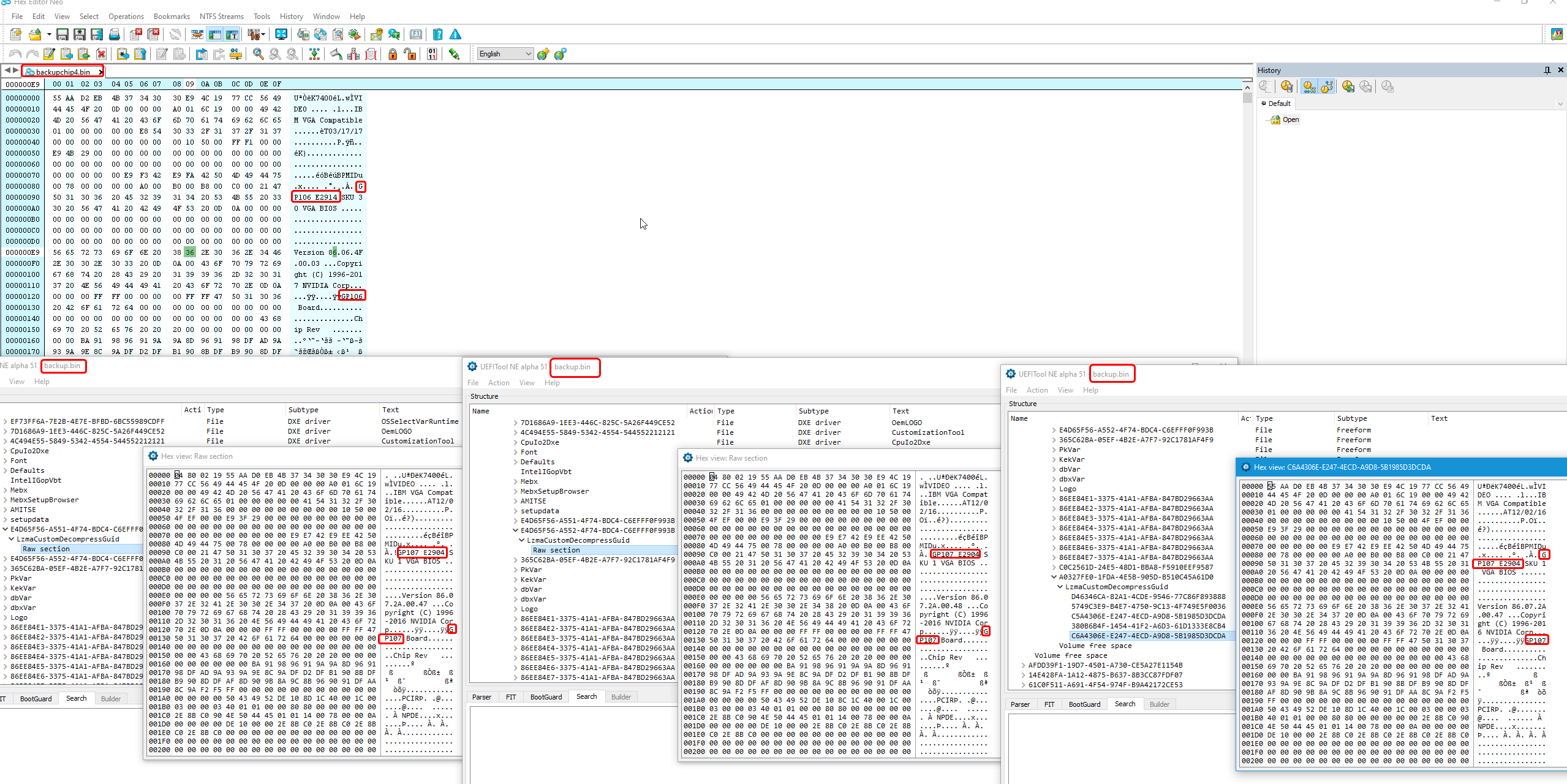
Yes, the chip you dumped has GP106, and the BIOS has GP107, that’s why I started asking about confirmation of the card via silicon and what you knew was in there etc.
Maybe they programmed in wrong vBIOS to that chip too, in their hunt to try and find the cause of the issue, which you already told them was EC FW
And if so, then they’d have to have replaced this chip too, since you know they can’t program a BIOS without replacing the chip 
Here check it out, top in hex editor is what you dumped off the chip, bottom x3 is 3 vBIOS in the actual BIOS
@Lost_N_BIOS
Which adapter specifically? And would I need any other equipment?
When you say replacing QFP package, do you mean replacing the actual chip or the FW on it?
I’m pretty confident this is an EC issue as the problems only started when I attempted to update that. I ran the files from USB and used the DOS command line.
I think I accidentally flashed the EC FW for the XMG A517-M18. The files for that are found here: https://download.schenker-tech.de/package/xmg-a517-xa517m18/. It’s what came up when I searched for my specific laptop, but I didn’t realise there were two results until afterwards.
Maybe try comparing the BIOS for the XMG A517-M18 with the original dump from the BIOS chip? I can’t think why it would be there, but maybe it would explain GP107? I’m not sure on the specs of that model.
I have images of the inside, but not with the heat sinks and fans removed. The image with the labelled SOP8 chips for example. I don’t see any differences between that and what it looks like now. All I can see is that the BIOS chip was replaced.
I don’t understand it either. Maybe they though the chip was busted? Maybe they didn’t have the equipment to program it themselves, so they bought a pre-programmed chip (although it was empty anyway…).
I really hope they haven’t swapped out the GPU. I wouldn’t know how to check even if they had.
I don’t understand why they’d have vBIOS in the BIOS and on a separate dedicated chip in the case of my laptop. In this case, the GFX card does have its own, right? Is it just for efficiency to be able to run from the same chip?
Not sure, it was linked in one of those threads I linked you to above. Ohh, I see @Falkentyne mentioned it here in post #6 but did not provide a link (sorry, I thought he linked it)
Hopefully he will reply here and link you to example item to be used with CH341A to program ITE 8587 via ribbon cable.
Replacing QFP would mean chip replacement, not something you can do with proper tools and previous experience. And even then, you’d still need setup or config to program the chip first
Is the XMG A517-M18 a compatible BIOS for your model, same graphics card at least? if yes, program in that BIOS and see if it starts or not, since you flashed in that models EC FW.
You flashing in EC FW for other model would not have anything to do with GP106/GP107 stuff we’re discussing.
Show me your before images, vs current, only the ones showing graphics card, so I can see if it looks 100% same card or not from what little we can see with the heatsinks on.
I explained why vBIOS is in BIOS above at post 203, this is common sometimes, but generally it would match the card that’s in the system.
And yes, in your case the vBIOS is stored on the card or board, since you dumped it off some chip.
Sorry I know nothing about these things. I was looking into it but I quickly realized I had no idea what I was talking about and accessing the EC without an experienced BIOS engineer around to help you was an almost guaranteed brick. Didn’t even consider trying to learn more. I made that post a long time ago when I was still thinking I could do impossible crazy stuff…
There was some sort of adapter on aliexpress that supported some ENE chips, but I don’t know how to access or program them. I thought these chips used the legacy "keyboard" port for access so required some strange magic drivers to program them, thus the need for a dongle. And messing around with EC’s…you can’t even desolder those chips…be careful with that.
@Falkentyne - Thanks for jumping in to let us know, sad to hear you don’t know about programming via ribbon cable though
Yes, I do think this one uses the ribbon cable as a method to program, via I2C method, I see UART and KB ribbon cable referenced in the schematic for this board at the chips location.
I guess his only option will be to try the incorrect BIOS so BIOS and EC match, if that fails then maybe I can try to make this BIOS compatible somehow (maybe it’s just vBIOS difference, we shall see I suppose  )
)
Thanks again 
You can buy pre-programmed chips, so surely you would just need to swap them out?
Or maybe that’s a challenge in itself…
From what I can see based off this comparison and this Amazon listing, the only difference is that the CPU is an 8th gen i7, instead of 7th gen. It appears to be the N850EP6 instead of the N850HP6.
Unfortunately, I just tried flashing the BIOS for the M18 to the chip (and verified) to no success. It appeared to even struggle with turning on and still didn’t POST or display anything on-screen. The file I flashed was N8xxEP6.BIN as it was the only file that matched the size. Downloaded from here.
I was suspecting maybe the difference was a 1050 and I thought it might explain GP107, but no, that’s not the case. I don’t know why it’s there.
So the vBIOS can be stored on the graphics card also? It can have a dedicated chip and also be part of the main BIOS? I was asking for more info as it’s a bit confusing. You’ve said that the vBIOS chip (25U4033E) dump you received had GP106 but the original BIOS chip (MX25L6473F) dump mentions GP107. What about BIOS.ALL, the updated BIOS file from the download portal?
If you can find someone to program this with everything you need for this system + the EC FW, then yes, that would work… If you had the skills and hardware setup to do the swap out.
Is the BIOS you tested the one that matches the EC FW you programmed in previously? If yes, please wait, tell me what is your CPU model and then I will make you a few BIOS to test. All with proper microcodes, and then one with your current BIOS vBIOS (GP107), and another with GP106 vBIOS
Yes, vBIOS can be stored on a chip on the GFX card itself, or near it, such as the one you dumped that contains the GP106 vBIOS.
Normally, it’s one or the other where you can find vBIOS, not both, so this also adds to the confusion. Rarely have I seen both, if ever. Maybe those repair guys flashed incorrect vBIOS to that chip and it was originally something else in there?!?!?
I checked that too before I mentioned any of this, BIOS.ALL also contains only GP107.
@Lost_N_BIOS
My CPU is the i7-7700HQ.
As far as I know, the EC FW I flashed through software was the one for the XMG A517-M18. I ran the file off a USB (ecflash). I linked to the download portal where you can download the matching BIOS for this a couple of times, but here it is again: https://download.schenker-tech.de/package/xmg-a517-xa517m18/. I’m interested in testing out any modified versions.
It’s weird that latest BIOS version (BIOS.ALL) for the regular XMG-A517 contains GP107. That would imply it’s supposed to have that. Why it would when the GPU is a 1060 is beyond me. I don’t know why the repair guys would even touch the vBIOS chip, but who knows?
As for swapping the chips, “hardware setup” is referring to the hot air rework station you mentioned earlier, right? I don’t have one of those but I have a heat gun.
Oh, also:
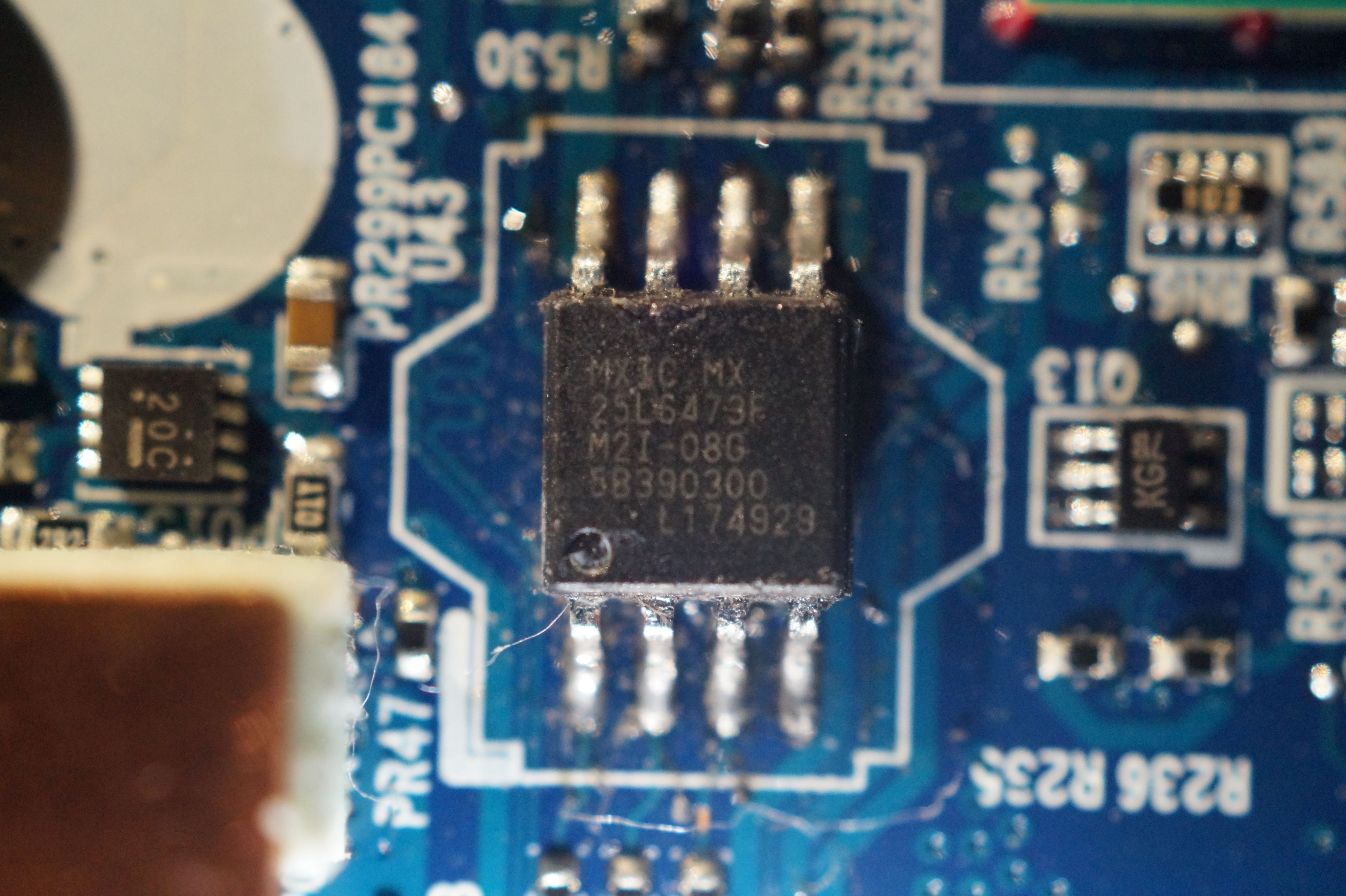
Here’s an image of the replaced chip. I wish they’d never touched it - the original one was much nicer looking…
@TheCM - Thanks. - No Nvidia vBIOS inside that BIOS. Here please test - Wait, what size is your main BIOS chip?
Ahh, there’s the issue with your test, your BIOS chip is not large enough to hold this BIOS, so only half would be programmed in anyway, so nothing we can do now
If you know how to solder to remove and replace BIOS chip, then you can solder in 16MB chip, then we can test some BIOS test files, but it may all be for nothing so kinda risky. It may be best to RMA at this point
Yes, that is why I’ve been saying this all along, about GP106/GP107 etc.
Yes, hot air station and bottom heating plate, it could be done with heatgun if you’ve done it 100’s of times and know what you are doing, but I’d never suggest that even to someone that knows what they are doing.
For someone without past experience doing this many times, and having the correct tools, even if you got it off with heatgun safely and did not melt/burn anything and didn’t rip out traces, you’d never be able to properly solder new chip back into place properly.
Really, this is not an option for general person to do, you need correct setup and lots of experience.
Can’t see image, please take a few from different angles and put in zip. I’m not caring about how the chip looks here, I’m interested in the solder work and what’s underneath that, how the pads look etc.
@Lost_N_BIOS
I was under the impression it was just over 8MB (8,192KB). That’s the size of the updated BIOS.ALL file I flashed and the original BIOS dump.
Why isn’t it large enough to hold this BIOS? The M18 BIOS I flashed was the same size. Unless I flashed the wrong file? It was labelled N8xxEP6.BIN and, since it was the only file that was the same size, I assumed it was the BIOS. This datasheet on the chip suggests three different sizes based on the mode it’s in. I don’t know, I don’t fully understand it.
Alright, I don’t think I’ll attempt replacing the chip myself then. However, if replacing the chip is the only option, I’m sure I could find and pay someone qualified and with the right equipment to do it for me.
I think we need to find a way to program it. I’m gonna need to some help with that though, as those guides only do so much (plus they don’t specifically say it will work with ITE8587 or ITE chips in general).
You keep saying RMA, which stands for Return Merchandise Authorization, correct? I bought this computer second-hand off eBay and it was listed as For Parts/Not Working. As I mentioned before, I fixed the issue it originally and got it up and running had but created a new one with the BIOS update problem. It also had this GPU issue that I didn’t know about until after. How would RMAing it work?
Here’s a .ZIP with multiple angles: https://ufile.io/wvvfga3a
I tried to get the solder pads in focus.
the black programmer is 5V wont that brick and fry the bios chip?
@TheCM - Yes, that’s what I mean, your BIOS chip is 8MB and the BIOS for your board is 8MB, but the BIOS for the other model which you think you flashed it’s EC FW into your board has 16MB BIOS
It’s “BIOS.ALL” equivalent = N8xxEP6(16M).13 = 16MB, the 8MB part you mentioned (N8xxEP6.BIN) is the BIOS region only (Programming that only into the correct model would brick it too ). This (N8xxEP6.BI) is similar to your models 6MB file (BIOS.ROM)
The only option I see for you now is replacing the BIOS chip with a 16MB chip, so you can at least see if we can maybe get that other boards BIOS to run on your board with the matching EC FW.
And that in itself will be huge issue, maybe not possible etc, due to the different CPU families between the two models.
Also, EC FW is usually part specific too, so that flashed in EC FW may not work at all with the controller or components on your board, so even if we could make a known working BIOS from the other model, the EC may be failing too.
So basically this is really a huge mess, I would personally RMA - Yes, return to place you purchased. Bummer, since you got on ebay as parts, this is not an option, sorry, you can’t RMA probably. You can try, but they’ll probably want receipt to do warranty coverage.
Time to resell as parts, hopefully you didn’t pay too much for it. I would do that, instead of putting more money, time, headache into this. Or find another parts/as-is board or entire system and pull it’s board out to put in this one, that way maybe you’d also get another better working GFX card too.
* Edit - Ohh, what a sloppy rework job that is!! They didn’t’ even clean up their mess, the owner would be so proud he’d probably fire them on the spot, unless owner did the work or trained the person his bad habits!
They even scratched the PCB right across a trace too, lifted the protective coating off there! Also looks like all cold solder joints, or cheap solder used etc. It’s too messy for me to even try and see if pads look OK/Undamaged
@jannyer - No, the black/gold programmer only puts out 3.3V to the chip, 5V is only used internally.
@Lost_N_BIOS
Soldering a 16MB chip probably won’t even work, I could look into it, but most likely scenario is that all that effort goes to waste and doesn’t fix it. Like you said, different CPU models. It’s doable though - I’m sure the chips are cheap and soldering 8 pads can’t be that hard.
Do you think programming the ITE chip is a lost cause? Isn’t that the best option right now? I think that’s what I should focus on.
Returning it to the seller isn’t an option, plus I’d probably get my money back and more from selling it for parts/not working again, but this time on eBay UK and not Germany (where it came from).
I really want to just fix it. One small mistake and it’s unfixable? I refuse to believe that.
I regret taking it to that repair shop. A massive waste of time and to make it even worse, they made a terrible job replacing a chip that didn’t need to be replaced.
@TheCM - Yes, I doubt it would work either, because I would have to “Downgrade” too much in that BIOS to attempt to make it work with your hardware, and even then we don’t know if EC FW currently in there is working with your hardware either
Even if we could make “Should be working BIOS” - then if/when it failed we still would not know if it was due to EC FW not compatible with hardware or if the BIOS still not compatible with hardware etc.
Soldering BIOS chip is not too bad, if you’ve had experience doing such. If not, removing it from the board may be pain for you, legs may be damaged/trashed, you might lift pads/traces may off the board if solder/tip too hot or cold, but at least they’ve already removed the stock lead-free solder so that does make it a bit easier.
Yes, programming the EC FW chip should be focus for now if you want to keep on this, but I have no idea how to help you figure out about doing that.
@chinobino @dsanke @ket @SoniX @CodeRush @davidm71 @Mov_AX_0xDEAD @gloobox @MiesMosel @PCGH_Torsten - Do any of you have any experience with Programming EC FW via ribbon cable (ITE 8587), or can tag someone in you think might? - Detailed Schematic here for this system model
If you can’t find info on doing this, then yes, sell for parts as-is and mention in bold that it was working right before you flashed in wrong EC FW, then someone that knows how to fix will be willing to pay much more than others only willing to risk a little on maybe being able to fix it.
It’s fixable, but not easily. If you flashed in wrong BIOS only, we’d have fixed LONG ago and you’d be back in business, you just happened to flash in the wrong thing into a part that is not easily corrected.
3.3V is not universial some chips operate lower and using 3.3V higher than optional will fry and brick your bios chip
The black version will output 5V on the SPI pins (CS, DO, CLK, DI) which is somewhat tolerated by most 3.3V chips, but will damage any 1.8V chip.
And if you are using a soic clip, you might risk damaging nearby components that are connected through SPI (e.g. embedded controller).
To be on the safe side: get the green pcb and a 1.8V adapter.
@Lost_N_BIOS I just read the last few pages and wow… just wow.
I always leave EC firmware alone because of horror stories like this (Surface Pro anyone?). According to this reddit post (by TheCM) he flashed the correct EC firmware for the XMG-A517 - maybe the download was corrupt? Who knows. The only way to find out what is wrong with that Notebook is to get another working XMG-A517, compare the chip sizes and dump them all (and even if you do eventually get it working the Nvidia GPU would need to be reballed = EXPENSIVE).
I hate to say it but it’s more time/money than it’s worth for a 3 year old notebook with a GTX 1060.
(I just quickly glanced through the previous posts).
As far as i know the EC firmware is located inside the main BIOS (search for ‘ITE Tech’) and will be accessed via SPI.
The other SPI chip is probably for the USB firmware.
Edit:
The EC has it’s own 128KB e-Flash storage that will probably just copy the firmware from the main BIOS.
Here are some ITE tools.