Hi ! I’ve been told to flash my BIOS with this CH341A Tool, to backup some of the part i missed during the BIOS save i did. I was told next to “add” the part of the BIOS i will flash with my backup and flash it all. Here is the thread : Broken BIOS of Mouse Computer - #12 by lfb6
I understood how to flash it but i have no idea how i should “add” all the pieces together and then flash. I’ve seen ASProgrammer or CH314A Programmer tools to do it on Windows. Could someone be nice enough to explain to me how to “add” these parts together to flash it ?
Please see also Linux universal CH341a programmer for 24xxx/25xxx/93xxx chip series IMSProg

1 Like
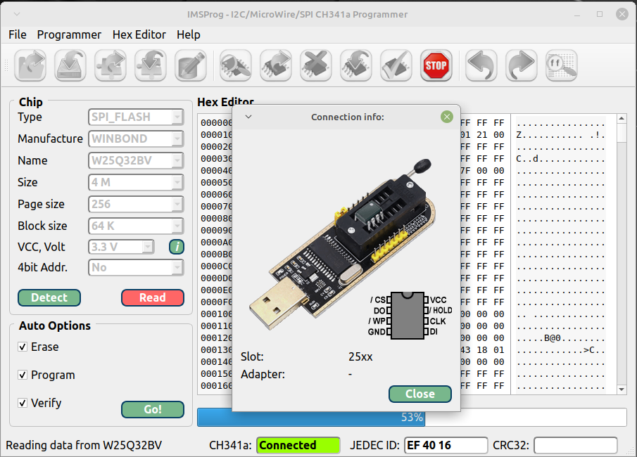
I wrote a presentation of the program in the topic
1 Like
I’ve tried using the ch341a programmer however each time I flash and verify the chip upon replacing the chip it boots momentarily then stops doesn’t post and continuously starts and stops.
For reference it’s a Z97M Plus
What are you trying to flash? Post / attach the file!
Hey is the programmer working with am5 boards?
That’s not dependig on socket but much more on board layout, spi type and package form, programming software and if the chip is desoldered or still on the board.
1 Like
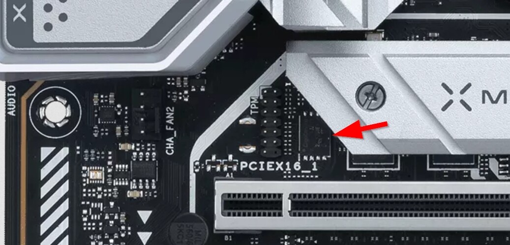
tnx. the board is x670e from asus, 256 Mb Flash ROM, UEFI AMI BIOS. how to figure out the spi type + package board - not sure.
also here is a photograph of the mb itself, i cant seem to see where is the bios - maybe can you help
https://dlcdnwebimgs.asus.com/gain/25c02cba-dbea-4503-bbce-71c132348f06//fwebp
Nice try.
Check the manual, search for chips that look like a spi, check their naming, read the datasheet, check other forums, maybe.
If you have to ask you need a pic with covers removed that’s so sharp that one at least can guess the inscription on the chip and maybe the markings on the board.
Good.
Now you need the type, then the datasheet to find voltage and package (looks WSON but which width?). Then you can begin to search for a software that knows this chip and ponder if you will invest in some Pogo Pins (you’d need the correct width specific for this package) since the SOIC clamp works poorly with WSON.
ok so i found out the chip, managed to snag a photo - its a Winbond “25q256jweq”
can you help me next
tnx
I’d recommend some reading.
The forum has a search function, maybe someone had this chip already? Look the documentation of the programing software mentioned here.
I don’t have such a board or chip and never programmed it. So it’d have to do the same job.
You need a programmer that supports 1.8V / a CH341 with 1.8V adapter, and you have to decide if you will try a SOIC clip first of just order a probe with pogo pins which is supposed yo give better contact for WSON. And you need to measure your chip if it’s WSON 6 or WSON 8 mm…
https://www.aliexpress.com/w/wholesale-ch341-wson-1.8V%20pogo-pin.html
(No recommendation just examples)
Why do you want to reprogram the firmware, bu the way?
1 Like
mostly to dump/export current bios(es) before upgrading, incase the new bios is giving me less or performance or adding bugs.
cause i dont know if this x670e boards of asus have the ability to revert to previous version… like those modern boards have ANY specific info/serial/mac/ etc…? i dont want the info to get deleted
someone knows?
Well, revert to previous version… There’s Asus Crash Free Bios 3 / USB Flashback which should recover the bios- but this normally covers just the static code, not NVRAM for example.
Resetting the RTC RAM by jumper doesn’t reset NVRAM values normally and if you have bricked the board by a setting Crash Free Bios or resetting the RTC won’t help you.
I don’t think you get a 100% answer here, it depends very much on the kind of brick, and waht Asus did implement.
There might be a serial, mac mostly for Intel systems with GbE. Serial might be relevant for warranty, but otherwise…
1 Like
I don’t know if this is the right place to ask for help with flashing bios with CH314A eprom flasher have problems .Could someone point me in the right place to post
thanyou
Could you give me some advise about a problem with writing to bios chip with CH314A flasher?
Do you really think this is enough information?