Can confirm Flashrom is the way to go. No messing about with weird Windows software that you have try different versions from. The hardest part about this process is getting the clip to make a good connection. I was temped to desolder it lol.
A note for those with dual bios chips, you gotta flash both chips. In Intel FIT just open a full backup of your bios, deselect generate intermediate images and build it again. Go to the build folder and you’ll see 3 files, one combined total and one for each chip. Usually one is 4mb with binary data and 8mb actual bios. Figure out which chip is which and flash them to correct chips. I didn’t flash both and the system didn’t post, went back in and flashed the other one too and the system posted again.
Flashrom ftw.
@KedarWolf - Do you still want info to the ebay seller for those items, not sure if you need now?
@snixel - Great you got it working finally, and nice to have confirmation of alternate working version/ID for that chip and CH341A too, thanks!
If you mean donate to me personally, send a PM, otherwise donate is at bottom of all pages in the forum 
hello to forum, this tool work with asus x370 prime pro?
thanks
@chrisg9 - Yes, what is chip ID and I can tell you if you need 1.8V adapter, or what software version might work best etc
what kind of Winbond do to got?
asus x370 prime pro got Winbond 25Q256JWEQ
i where just trying too help out not ask about anyting but if Winbond 25Q256JWEQ need 1.8 adapter that is good too know :=)
but where also trying to find any kind of White papers for Winbond 25Q256JWEQ
@chrisg9 - Yes, you need to check chip ID, you may also need 1.8V adapter
@SweaNisseGaming - Not sure what you are asking there?? But for 25Q256JWEQ, you for sure need 1.8V adapter
Some discussion about that chip here - Windows XP 32-Bit and Server 2003 32-Bit on Modern Hardware (69)
You may need to use flashrom, or find a compatible programmer for that chip, general CH341A software does not list it in public versions (maybe paid, you’d have to check), ASProgrammer also does not have support right now either
CH341 Programmer v1.1.1.32 may work, unsure, it only have W25Q256 as chip choice
25Q256BV is supported in both general CH341A software1.34, and W25Q256FV is in CH341A 1.30 and Asprogrammer 1.41 and colibri (all included in this link, except for Asprogrammer - It’s here)
^^ This is 3V BIOS, would need edited in advance to be set for 3-3.3V BIOS operation before you program it into chip.
Hi macnb,
Great solution (Post 143)
Thank you so much for posting it, together with the easy to follow images.
Nice to see someone applying some real fault finding to a problem, and solving it with a well thought-out solution.
But why did you need to also connect the PC PSU to the mobo, as well as your modded external 3.3v PS?
If your (modded external 3.3v) PS was still not able to deliver the required current to the mobo 3.3v rail, wouldn’t it have worked with just the PC PSU, and the original CH341A 3.3v supply?
Also, as you did connect the PC PSU to the mobo, why was the 3.3 v rail still sagging?
Shouldn’t the PC PSU have been able to cope with it?
Many thanks
Hi.
I believe I flashed the wrong BIOS for my model and now my laptop won’t POST. Its fans go and the keyboard lights up, but I’m having trouble getting it to do anything else. After a few minutes it beeps (long beeps) 35 times and shuts off.
I downloaded the files from the official download portal, but I think I must have accidentally gotten the wrong one (I needed the one on the right). I changed my boot order and updated the BIOS from a USB stick formatted for FreeDOS. I ran the commands in DOS and went ahead with it.
The thing is, there are two .zip files - BIOS and EC/KBC. I decided to update the latter first.
Anyway, I found this forum post and, as my last resort, decided to follow it hoping it would fix it. I bought the CH341A Programmer and SOIC8 clip and eventually got the hang of it with Ubuntu Linux. I ran into a couple of errors, which ended up just being because it wasn’t mounted correctly (don’t trust the RUN LED) and then another telling me my chip was supported but was then unknown when I selected it (turns out you have to select the whole group including the slashes).
I then managed to get a new error complaining that the image size needed to match the chip size.
The only file that matched the chip size was in the BIOS folder - BIOS.ALL. I flashed it according to this guide, which seemed to work, but it didn’t fix my issue. However, the beeps changed to be 1 long beep, then after a while 8 long beeps, then 5.
I also tried padding the ECflash.BIN and BIOS.ROM files out to match, but this also didn’t change anything. No display, just power, fans and lights.
Is the EC/KBC BIOS updated differently? How are you supposed to update both of them if it overwrites the chip each time? I’d appreciate any help I can get. Perhaps someone would be kind enough to walk me through it a little more? I’m hoping I’m just doing something wrong and it’s not a lost cause as it booted fine before all of this.
Also, if you need any more info, please ask.
@TheCM - You also need to update EC FW too when you flash BIOS, so maybe you skipped that part as well?
Yes, not sure which you need to do first, they should have this mentioned somewhere in a BIOS update guide, or the manual etc. But yes, one should be first and then the other, and you can’t mix and match EC/BIOS versions either (ie older of either new newer, or newer with older etc)
BIOS.ALL is what you would write with programmer, this contains the FD/ME and BIOS region (as oppsosed to BIOS.rom, which is only partial BIOS content, just the BIOS region)
Hopefully you made a dump first, yes? If yes, send to me, I will make you fixed BIOS with all your original details from the bricked BIOS (serial, MAC ID etc)
EC FW would be another chip, size will be 128KB-1MB and you need to write EC FW to that (N85HPTR1.08), do not add any padding to this, it should fit the chip or if not then maybe yes you can pad out with FF, but it’s probably correct size already.
How you say? You write BIOS to BIOS chip and EC FW to EC FW chip, it’s two different chips you need to write to here.
So, looks like you need to write BIOS back to BIOS chip, and then find the EC FW chip so you can write it in as well
If you cannot find EC FW chip, show me images of both sides of the board, from a few angles, and please put them in a max compressed zip.
Well, I attempted to update the EC/KBC through software using commands before I messed it up. I ran the ECflash.bin file from the USB stick. Since then, I have tried flashing BIOS.ALL to the chip using the actual programmer and it’s not fixed it.
When you say first dump, do you mean backup? Because, no, I didn’t know how. Unfortunately the manual didn’t include info on it and there wasn’t much in terms of detailed documentation for updating the BIOS in general.
What is FD/ME?
Where do I find this EC FW chip (what does FW stand for?) and can I use the CH341A SPI programmer to write to it also or do I need another tool? Perhaps you can tell me what to look for in terms of labelling and such?
If I understand you correctly, you’re saying I need to also write the EC FW file to the EC chip in order to fix my issue?
Hold on. Just uploading the image of what I think might be it!
@TheCM - You need to program both chips with programmer. EC Flash via USB would not have done anything if you typed in ECFlash.bin, you would have had to run ecflash.bat if in DOS or EcFlash.NSH if at EFI Shell
Yes, I meant a backup as in when you first got the programmer, and any time you use a programmer, you should make a backup dump by reading, verifying, then saving.
If you do not have that, do you have any previously made software backups of the BIOS? Can be with any tool, any time in the past.
FW = Firmware. Yes, if it’s a standard SOIC chip then you will write to it with CH341A, after you locate and dump it first
FD = Flash Descriptor
ME = Intel ME FW Managment Engine)
GbE = Intel Gigabit Ethernet (also sometimes part of the BIOS chip contents, but not in this BIOS)
Yes, you need to write BIOS to BIOS chip, and be sure you are writing it to the correct chip. Then same for the EC FW, write it to the EC chip and be sure it’s not the BIOS chip (by dumping it first and letting someone check for you)
Send me some images of the board (in a max compressed zip please) and I will find the chip for you, it should look just like BIOS chip, but will not be on the graphics card (if graphics card is part of board, it wont be the one near graphics either - that would be graphics vBIOS chip)
I need to see the board, both side, not super cropped off chip area images only, thanks
Since you initially thought you made mistake on which BIOS you should have flashed, how do you know “Right” one is correct now? Just wanting to be sure we are using the correct files
@Krzyslaw - What software version did you use that you know is OK to write to MX25L6473F
If it’s not immediately obvious, this is my first time ever attempting to update a BIOS. Thanks for taking the time to explain it to me.
I may have been confused about the file type. It was probably ecflash.bat then as it came up with the update prompt and progress bar etc.
Yes, when I got the programmer I think I actually did make some backups now that I think of it. Following this thread. Although, they don’t seem to be of much use from what I can tell.
My laptop is an XMG A517 (Model: N850HP), so I’m pretty sure it’s these files.
I believe I found the chip. Do you still need a photo of the entire board?
@TheCM - It’s OK, don’t worry, people have to do this all the time as their first time, well get there
Yes, I need to see images of the entire board as mentioned, both sides if possible, otherwise I can only guess if this is EC chip and not vBIOS etc.
Unless you dump it and send me the file to check, which you should do right now anyway. Read, then verify, then save file and send to me. Do not use AUTO and do not erase or write anything until I’ve told you the dump was OK
Never mind, no, that is not a BIOS or EC chip
Send me those files you dumped previously, thanks! Maybe we can salvage your serial or MAC ID etc from them
I’m not sure how I overlooked these two chips, but perhaps one of these is the EC chip? I believe that’s all of the chips of this type on the top side of the board.
My guess is the second one, since it’s so similar to the BIOS chip. It’s further away though, right next to the HDD. The first is next to the CMOS battery and the one I sent earlier is next to what I believe is the Wi-Fi card.
I could still try and take some photos of the whole board, but I doubt you’d be able to read most of the text unless I get some close-up shots. You’re also suggesting there may be more on the underside? That’ll mean unscrewing the board and such to see. It is a laptop after all.
As for the backup files, yeah I can try and get those for you. I’ll have to boot up Linux again to get them. I think there’s the original and then some backups I created after I started flashing to the chip,
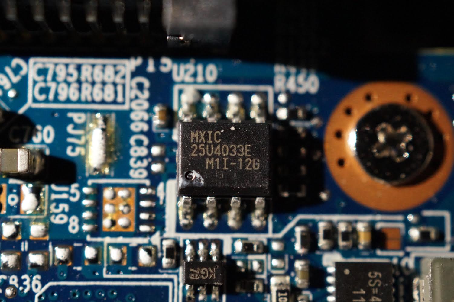
@TheCM - Yes, that one MX25U4033E, this is either BIOS chip or EC FW, or total BIOS is split between both 8MB and 4MB chips, this is 4MB - 1.8v chip so you need 1.8v adapter (like this - https://www.ebay.com/itm/313073675375)
Send me the files you said you dumped previously, so we can at least try to see what’s going on here and what’s at least on that chip (if any of those were proper dumps)
So, to get this fixed, no matter what, you need to order that 1.8V adapter so we can dump and or write to this chip too. You can get it on Amazon too, probably shipped faster from there but more $$ (and other sellers on ebay may ship quicker too, above link is slowest/cheapest)
I do not need more images of the board now, thanks. We’ve found both chips that would be BIOS or EC FW etc 
Unless either of these we’re discussing are on or near the graphics chip, then I still may need to see entire board (don’t care about reading chip ID’s, only need to see so I can point out possible BIOS chips)
I knew I should have just gotten all three items in a set, I’ll check eBay now to see if I can find one as your link is for eBay US.
So, the two MX25 chips - one is BIOS and one is EC? Or it’s possible they’re both split between both chips? Is it possible to find out which is which? What if I flashed BIOS.ALL to the EC chip or something?
Here is the original backup I made before writing to the chip using the programmer, but after I attempted to update in DOS.
(Too big to upload here - 8MB+) https://ufile.io/hd2owp8y
--------------------------
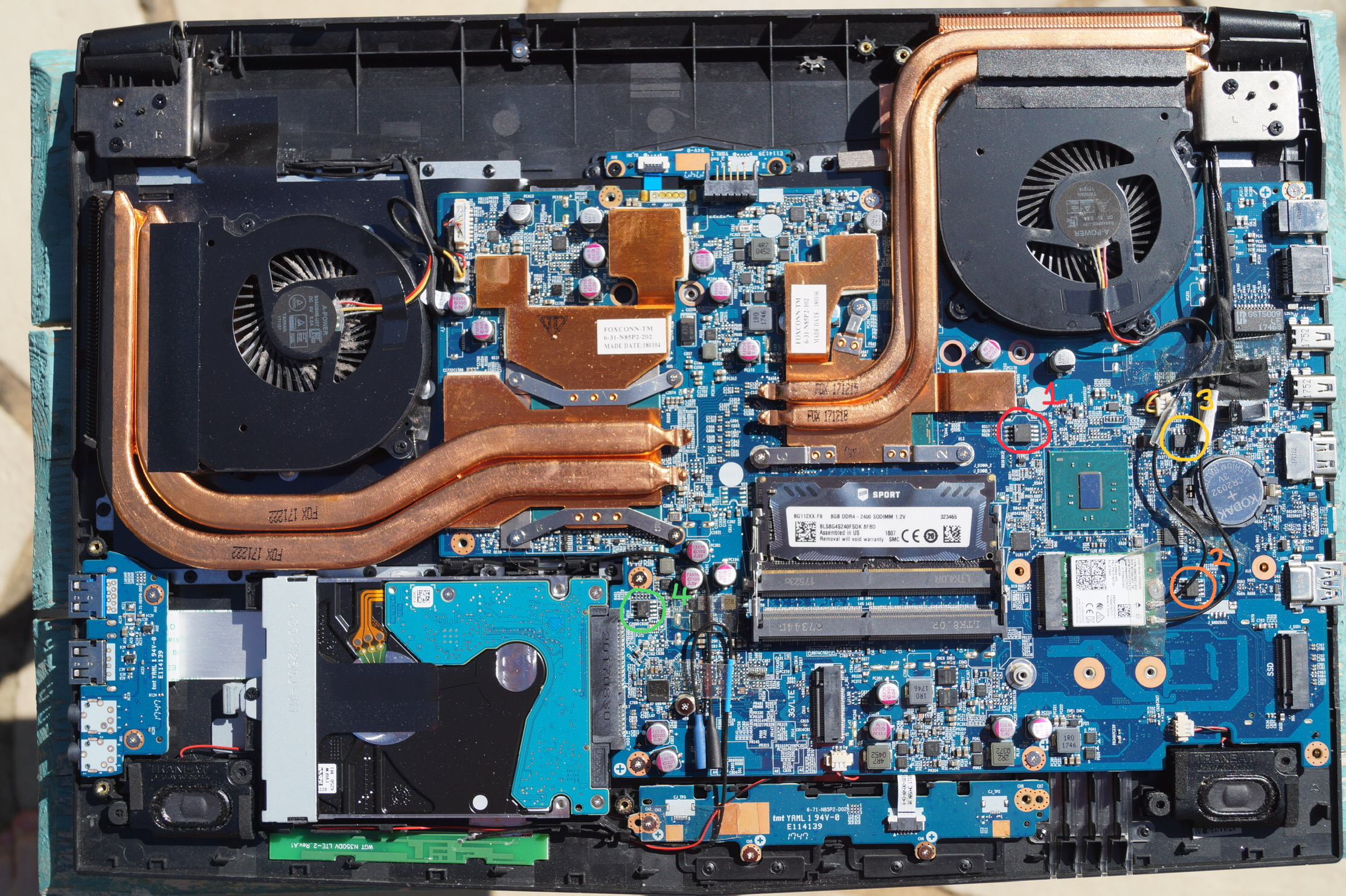
I had to step outside to get the lighting for this one, but here’s a shot of those whole board since you expressed concern over the chip’s placement in relation to the graphics chip.
I labelled them in the order that I sent the images. (1 is the chip I wrote to with the programmer, 4 is the other MX25 chip)
Edit: Do I need the 1.8v SPI adapter for the second chip I found or both? When I read this guide it said that was for AMD boards, so I decided I didn’t need it. Will I be able to read it and create a backup for that chip too?
@TheCM - Just search ebay for item 313073675375 - this is not a US Listing, it’s in China Anyway, it’s only example to show you, best way to search is this terms (all categories) >> 1.8v adapter SPI
I don’t know if one chip is EC and one in BIOS, as mentioned, it could be split BIOS across two chips, or EC one one and BIOS on another. We can’t tell until you give me dump from each chip.
If you flashed BIOS to wrong chip, nothing you can do except fix it later when you can program both chips. DO NOT write anything to the other chip, or erase it, once you get this adapter, so we can see what is there before you do anything!
What is BIOS ID per # in that image? Only #1 looks like BIOS chip, 2-4 do not look like the other chips you showed me, but hard to tell which are square and which are rectangle for sure.
But I guess that MX25U4033E is much more rectangle than usual BIOS square so I guess it’s one of those others. None of them should be vBIOS, since it is it’s own card, the vBIOS for that if stored on card would be on it’s own PCB usually
And, checking your BIOS dump now, I see Nvidia GP107 vBIOS in BIOS, so I now doubt any chip on the board is vBIOS, since it’s in the BIOS itself!
I assume the following, correct?
#4 = MX25U4033E - 4MB
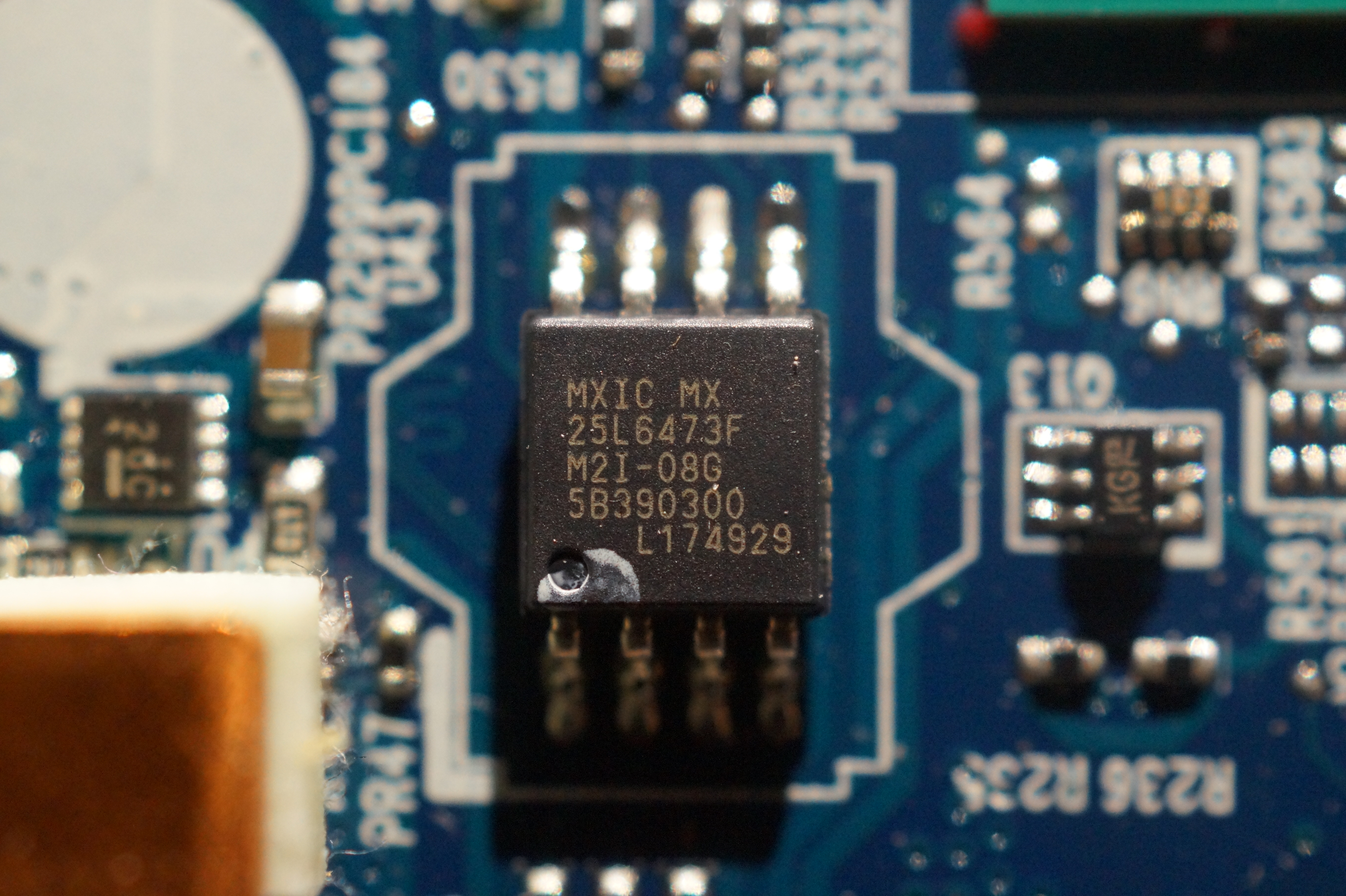
#1 = MX25L6473F - 8MB
Also, looking at the board now, and images of chips, I think this is is also possible candidate, so maybe vBIOS is on one and not on the card PCB.
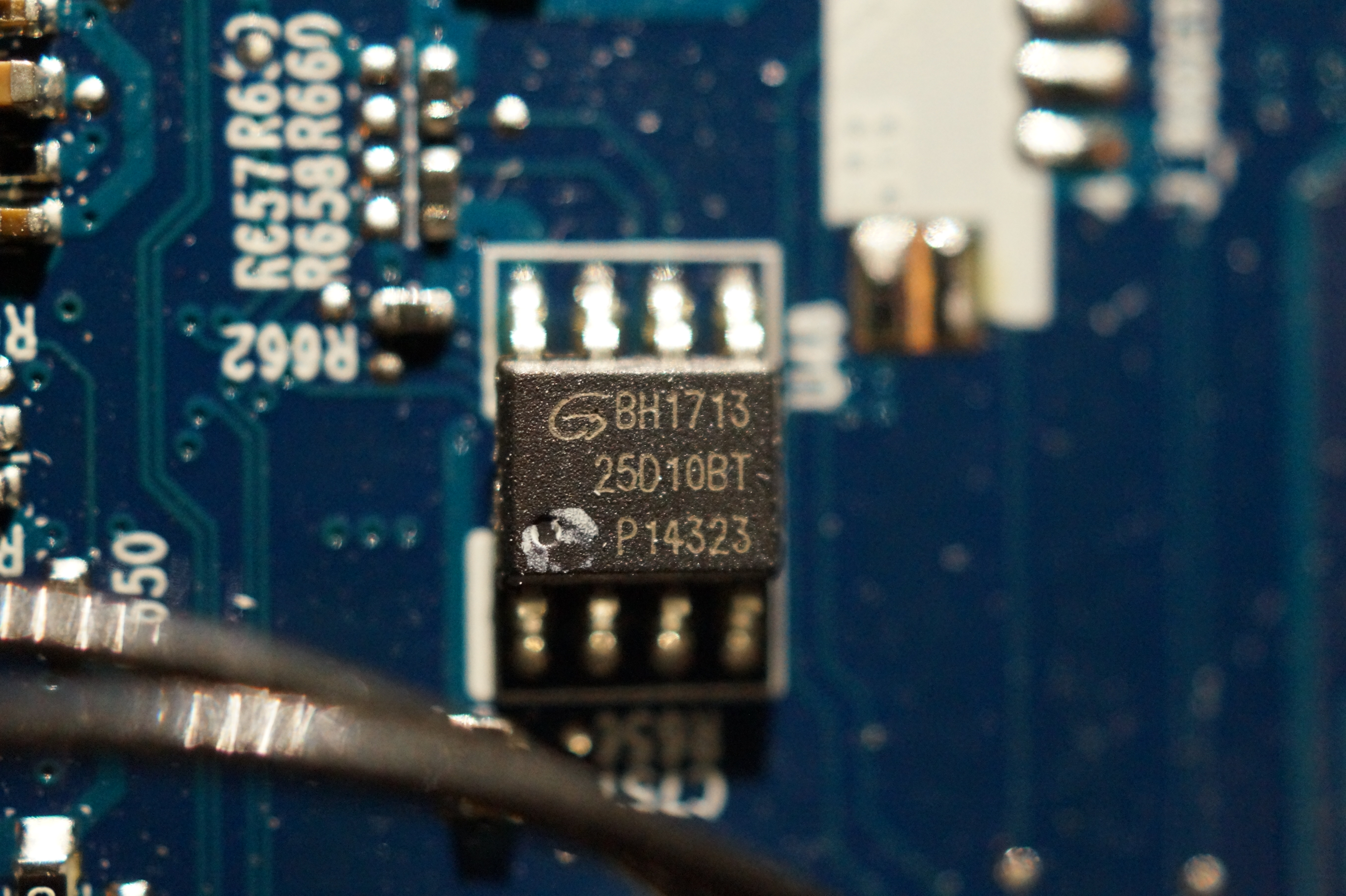
25D10BT << This is Gigadevice 25D10BT (128KB) Probably EC FW chip, dump this and send to me so I can see what is on there. Use all of these, and send me dump from each so we can compare, or you can compare, if all same, just send me one
CH341A v1.31(1.4) (CH341AFree) + ASProgrammer 1.41 + CH341 Programmer v1.1.1.32 + Colibri + 1.34 and GD2510 ID
When possible, use correct 128KB size, and GD25D10 ID (may have to use GD25Q10 in some programs)
What chip did you dump above file at uploadfiles.io from, and are you 100% sure? This is complete BIOS
Whichever chip this came from is the one you need to be programming BIOS back to, and due to you dumped it, and it’s size (8MB), it must be MX25L6473F
Program BIOS.all to this chip and see if it will start the board or not.
So, unless the 4MB chip is messed up, you may not need 1.8v adapter!
I’d go ahead and order though, just so you have, and in case you need, but hopefully we can get it working before having to dig into this chip after some long shipping wait
Sorry, not sure what guide you are talking about, but no programmer or item mentioned here is AMD specific
The numbers in the image correspond to the order I sent the images in.
#1 - MXIC MX 25L6473F M2I-08G 5B390300 L174929
#2 - BH1713 25D10BT P14323
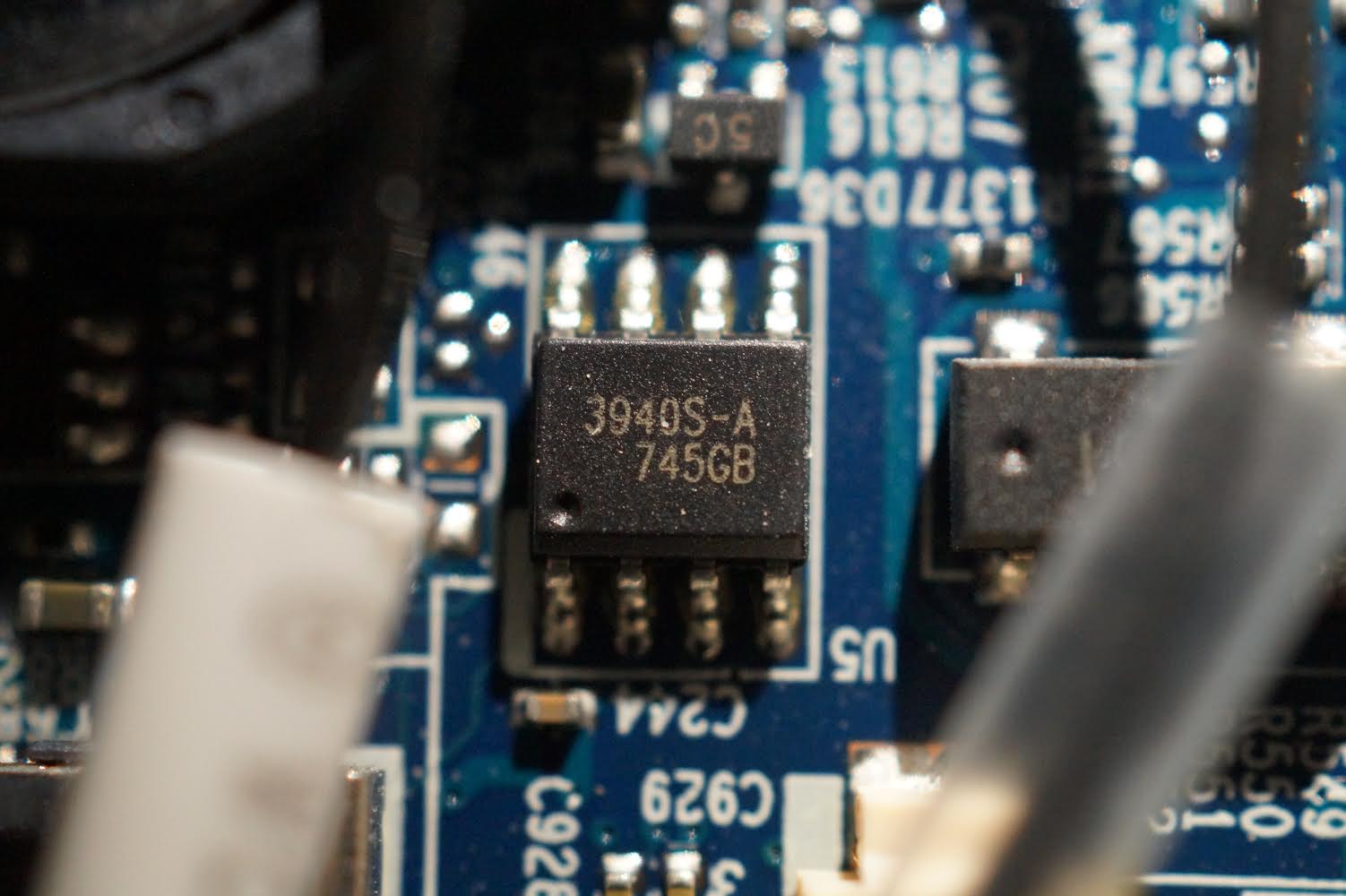
#3 - 3940S-A 745GB
#4 - MXIC 2574033E M1I-12G
They’re all labelled correctly. #4 is the one by the SSD.
The only chip I have used the programmer with is #1. The backup dump file (uploadfiles.io) I created is from that chip before I wrote to it. I already tried flashing BIOS.ALL to that chip with no success.
I won’t be able to get a dump file from that chip for a couple of days, but I’ll try ![]() You’re suggesting #2 may be where the EC FW is stored?
You’re suggesting #2 may be where the EC FW is stored?
What are these? Programs? What do you want me to do?
This one is BIOS >> MX25L6473F and your dump looks OK, have you tried writing that back yet?
Either way, that or BIOS.All should start the system, if there is no other issue, and if you manually confirm the write is OK >> close program after write, do not start system, open program, read, verify, save and then compare in hex with what6 you wrote, if 100% match then software verify during programming is valid
But, sorry, whatever BIOS version that backup is, you would need matching EC FW too  So if you’ve updated EC FW already, then you probably cannot use that BIOS, so ignore that mention, if you did update EC FW previously - I think you said you did, so using that is not option unless you have the old EC FW to write to that chip too.
25D10BT may be the EC FW chip, especially since EC FW file is 128KB too.
Yes, those are all different programs and or versions etc. All are included in this package - http://s000.tinyupload.com/index.php?fil…213094641136166
Dump EC FW chip with all those things I mentioned, then we can compare, see which tools reads it properly and also make sure it’s at least looking OK etc.
Sorry, I didn’t realize he said that on first page/guide, 1.8V BIOS chip is used on any board Intel or AMD, does not matter.
As you said, you won’t be certain of which chip is which until you get a dump from them.
However, you told me #1 was complete BIOS and that’s the one I used the programmer to flash the updated BIOS.ALL. It’s also the one you have told me I need to be programming. So this is the BIOS chip.
And yes, I’m pretty sure the problem is that I initially updated just the EC FW with the wrong model version. If I flash the correct model (and latest version) to that correct chip (#2), surely it’ll fix my issue. You’re thinking this is the EC FW chip
Also, will I need the adapter to read/write from this chip? (The GigaDevice one)
So, what do you think chip #4 (MXIC 2574033E M1I-12G) is?
—-
Some other questions, just because I’m curious:
(1) How are you reading the BIOS files? Do I need one of those programs to get readable text and not jumbled nonsense characters?
(2) - What do the other numbers on the chip refer to? When I look up the GigaDevice 25D10BT chip, I can’t get any results including the other two lines. Do they matter? Is there any difference between other 25D10BT chips? Same for the other types of chips.
BH1713
25D10BT
P14323