[Guide] Using CH341A-based programmer to flash SPI EEPROM

I would say the chip with the red paint on it

Thats my guess. Thanks.

Just out of curiosity, did it work?
What did you use, a SOIC clip and CH341A Programmer or did you desolder the chip?

Actually I didn’t have to use my CH341A. Was able to reflash at DOS prompt after plugging the card in an older computer. I was so much looking forward to using the usb programmer but didn’t have to. Thanks.

just a quick thanks to @Wootever for making a windows version of the flashrom program. used it to resusitate a mobo which I needed to hold on to for at least a few more months. the hard part was just soldering the BIOS onto the programmer, the flashing itself was a total breeze.

Hello,

I’ve got the black golden “CH341A Pro” mini programmer, too.
Could read to my BIOS chip Winbond W25Q32V in parallel USB mode without any problem. The W25Q32V is be a 3.3V-BIOS (2.9V - 3.7V).
So I had no problem & no need to do the 3.3V mod. Proofed with analog voltmeter tool.

Maybe newer versions of CH341A black/gold or generally some of that versions could work at 3.3V and some not.
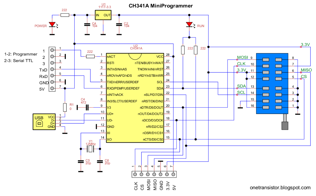
Or am I thinking wrong? Is the problem somewhere else? I have 3.3V @ chip 25xx pin 7, 11, 12 … and chip 24xx pin 16, if you look on the shematics picture.


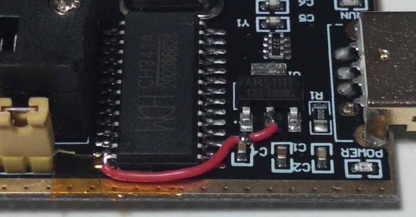
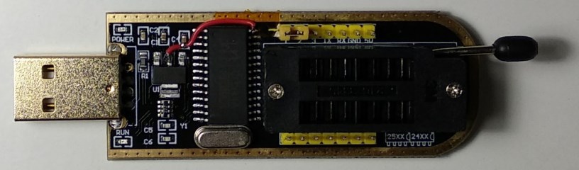
Anyway here’re photos how to do the 3.3VoltageMod on CH341A black/gold version, if needed:

Best regards, MiMo

Hİİ…i have a biostar x370gtn motherboard wit w25q128fwsq bios chip and it crashed when i update… so i bought a ch341a and when i connect my chip it didint recognize the chip automatically also didint read and write… should i use a 1.8v adapter… is there an advice for me ? thanks for your help

Do you have it all connected properly? Please post some images of the adapter with cable attached, another showing specifically how your cable goes into the adapter, how you connect the cable to the motherboard and a image of the BIOS chip itself with nothing connected so we can see it’s orientation
Often cables are just connected backwards. Make sure red wire goes to pin one on the BIOS chip on the board (Little dot on chip, or 1 or white triangle on PCB usually), and then red wire must go to pin one on the adapter. On the adapter use middle socket, pin one is on lever edge in the middle
Did you try all software versions, specifically newer ones? Sometimes you need to use a few versions until you find one that works. And separate driver must be installed to. Here is package with all versions I have found, and the driver you need - https://www.sendspace.com/file/gtcmvd

You may need 1.8v adapter, but sometimes it works OK without it.


This fix is simpler: [Guide] Using CH341A-based programmer to flash SPI EEPROM (7)

@oldirdey - please explain/show why the above mods are not necessary and perpetuated fake news (Which I used to do as well)

@Lost_N_BIOS

what Do you want to hear? :slight_smile:

All CH341A programmer have one thing in common, the SPI chip is always getting 3.3V VCC from AMS1117. Only difference is that some programmers have pin 28 from ch341a chip powered from usb (5V) and some are powered from AMS1117 (3.3V) According to this only the data lines are affected from 5V "issue". You can mod it, but you don´t need to mod it.


Is my opinion this mod is not so good. Take a look at datasheet page 3. If you power the CH341A chip with 5V then pin 9 should be connected to 0.01uF capacitor. If CH341A is powered from 3.3V then pin 9 should be connected to VCC.

https://drive.google.com/file/d/0B-RbkSU…zRMekxTWHM/view

Most 3.3V flash chips might be tolerant up to 5V. But if you are using a soic clip, other connected components (e.g. embbeded controller) might not withstand the 5V on the data lines.

I only wanted you to calm their concerns and worries, that this mod is not necessary, like you did for me in PM


flashrom p1.0 for Windows (source) including libusb (source).
- added some additional commits (improved timer, icon and version information, warning in alternate mode)
- added a very simple batch file (flashrom.cmd) for probing, reading and writing
- certificate for the winusb driver will now be removed after the installation

Usage:
- Execute [driver/Install.cmd] to install the winusb compatible CH341A driver.
- Start [flashrom.cmd] and enter the given function number.

virustotal.com

flashrom_p1.0.rar (153 KB)

The following programmer comes from a store "e-yuediy" in Taobao China. I think it’s the only one among the CH341A programmers which properly takes care of VCC and V3 of CH341A. Sadly to say that I can’t find it in either Aliexpress, Ebay or even other stores in Taobao China.

CH341A.jpg


CH341A-2-1.jpg


https://item.taobao.com/item.htm?id=19524325315 or
https://e-yuediy.taobao.com

The most important specifications are,


WCH CH341A official driver download
http://wch.cn/search?t=all&q=ch341a

CH341A Programmer Online User Manual v1.0 in Chinese
Https://m.book118.com/html/2015/1101/28283087.shtm

This CH341A programmer is also correctly working, VCC is powered with 3.3V and V3 is connected to VCC.

hii. i have an biostar x370gtn with W25Q128FWSQ 1.8v … at first i replace it to programmer without adapter… did it fire? and is there a demonstration how i replşace the adapter and soc8 clip ? at last the usb programmer 1.3 or 1.29 suitable for my chip ?
i cant recognize it to programm why please help me

You need 1.8v adapter probably, I am not certain because I have not tested 1.8v chip at 3.3v to see what is reaction (Hot chip only, or fail to read/write?)
https://www.ebay.com/itm/253208845481

Is your chip removable, or soldered to board? If removable, BIOS chip goes into programmer in the middle socket, pin one on level side, making sure BIOS divot or half-circle notch goes in middle like little sketch of BIOS chip on the programmer.
That little notch must always go back into board same way you removed, there is notch in the socket plastic too on same side as BIOS chip notch.

If you are using cable, red wire must go to pin one on the motherboard side of BIOS chip, usually there is dot on the BIOS, or paint, or white triangle or arrow on the board PCB pointing at pin one.
Then on programmer side, pin one is red wire, must be in the middle of inner set of 4/4 slots, red wire on lever side of the programmer.

Software, you have to try versions until you find one that works, and sometimes you cannot choose exact chip ID, but pick one close (Like maybe W25Q128FW doesn’t work, but W25Q128FV or BV does etc)
Once you can read and get a verified file (Buffer/memory match chip), then save, and then you can safely write but make sure you have verified file before you save it and write anything to the chip, or you will loose board details (Serial, UUID, LAN MAC ID etc)

Hi all. This is my first post. I have been reading very carefully the whole thread and I would like to ask you about a weird issue I found while using a CH341A programmer and a SOIC test clip.

My programmer is a black version and I am going to flash a Winbond w25Q128fv chip on a MSI Cubi 2 Barebone. I tried both version 1.29 of the software and flashrom.

Before attempting to flash the BIOS I first read it and verified the buffer, and it seemed ok (whether connected or disconnected to the PSU) so I dumped the buffer to a backup file. But then I removed the clip, booted up the system, shut it down, reconnected the clip and tried to verify the BIOS against the previous back up and it did not verify anymore. So I backed it up again, compared both backups with Beyond Compare, and it seemed that certain areas did not match (178KB out 16MB are changed)

Do you think this is related to the fact that I did not remove the BIOS from the motherboard?