@SilverPuppy
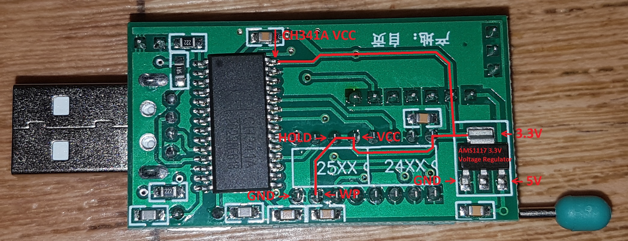
Unfortunately just found out that the black pcb version supplies 5V to the chip due to an improper design (CH341A Programmer Schematic, CH341A Power Supply Fix).
Might be possible that it would fry 3.3V chips that are less tolerant to 5V.
The green pcb version works correctly by supplying only 3.3V to all pins, but i would also recommend to order the 1.8V adapter as an secondary safety measure.
Green PCB:
Black PCB:
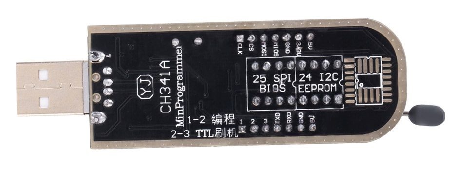
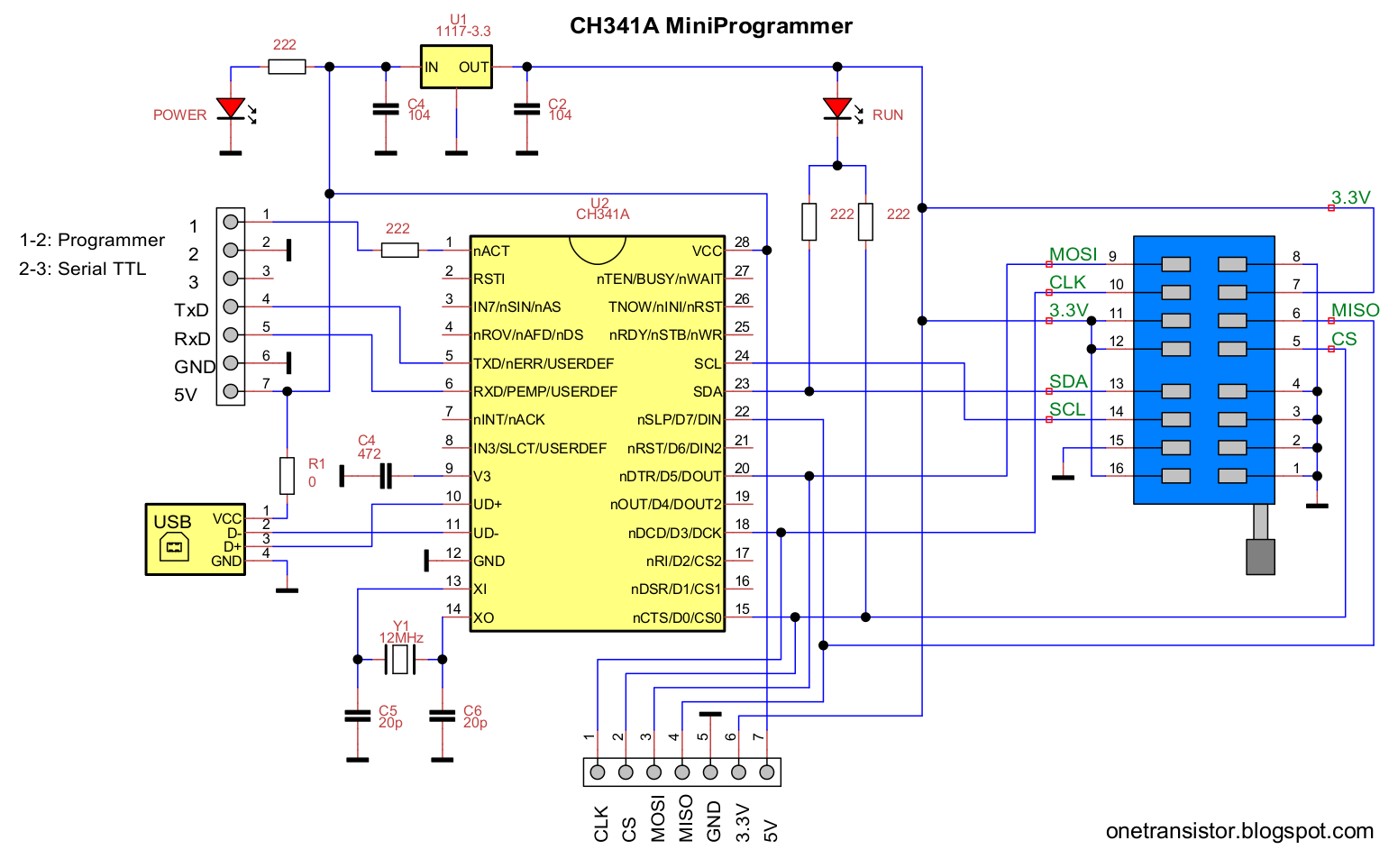
Pin Overview:
The voltage on CH341A VCC (5V or 3.3V) provides the same amount to CS, DO, CLK, DI
Edit:
About the MX25V4006E, it seems that flashrom has no specific support, but the corresponding MX25L and MX25V versions seems interchangeable.
From flashchips.h:
#define MACRONIX_MX25L4005 0x2013 /* Same as MX25L4005A, MX25L4005C, MX25L4006E /
#define MACRONIX_MX25L8005 0x2014 / Same as MX25V8005, MX25L8006E, MX25L8008E, FIXME: MX25L8073E (4k 0x20) */
From the Macronix driver:
#ifdef MX25V4006E
#define FlashID 0xC22013
(0xC2 is the vendor id and 0x2013 the chip id)