Wow. Wootever, you are the best of the web. Someone who would go to all the work to build that, and then just throw it out there for anyone to use is a scholar AND a gentleman. ![]() Granted, that’s the whole FOSS community modus operandi, and kind of how the Bus Pirate came to be, but still…I’m seriously appreciative.
Granted, that’s the whole FOSS community modus operandi, and kind of how the Bus Pirate came to be, but still…I’m seriously appreciative.
I guess I’m buying a CH341A now. I bought a TL866A instead because it supposedly supported ICSP, but then I got it home and found out that it only supports it on a handful of chips, and the uber-common 25SPI chips are not supported for ICSP and it won’t work. >:( I only didn’t buy it because it was late at night and I interpreted a warning about being unable to write to ESMT 25s as being unable to write all 25SPI chips. My bad. I’m working with Macronix so it should be just fine.
Is there any reason you can think of why it wouldn’t work with the MX25V4006E family? Datasheet says they run 2.5-3.6 volts, which puts the CH341A in spec. It’s on a Toshiba hard drive board.
@SilverPuppy
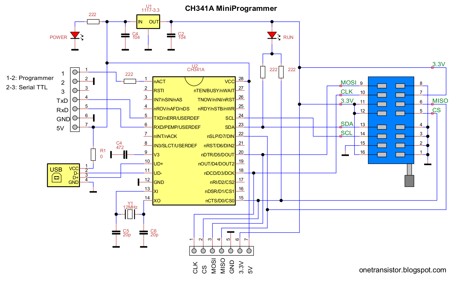
Unfortunately just found out that the black pcb version supplies 5V to the chip due to an improper design (CH341A Programmer Schematic, CH341A Power Supply Fix).
Might be possible that it would fry 3.3V chips that are less tolerant to 5V.
The green pcb version works correctly by supplying only 3.3V to all pins, but i would also recommend to order the 1.8V adapter as an secondary safety measure.
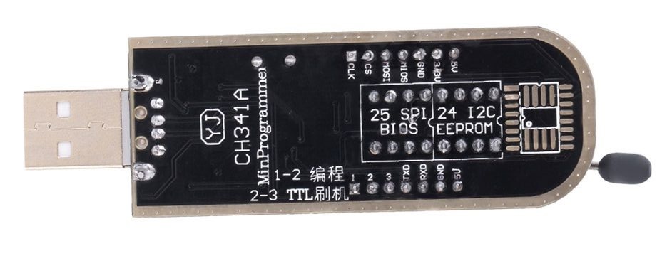
Black PCB:
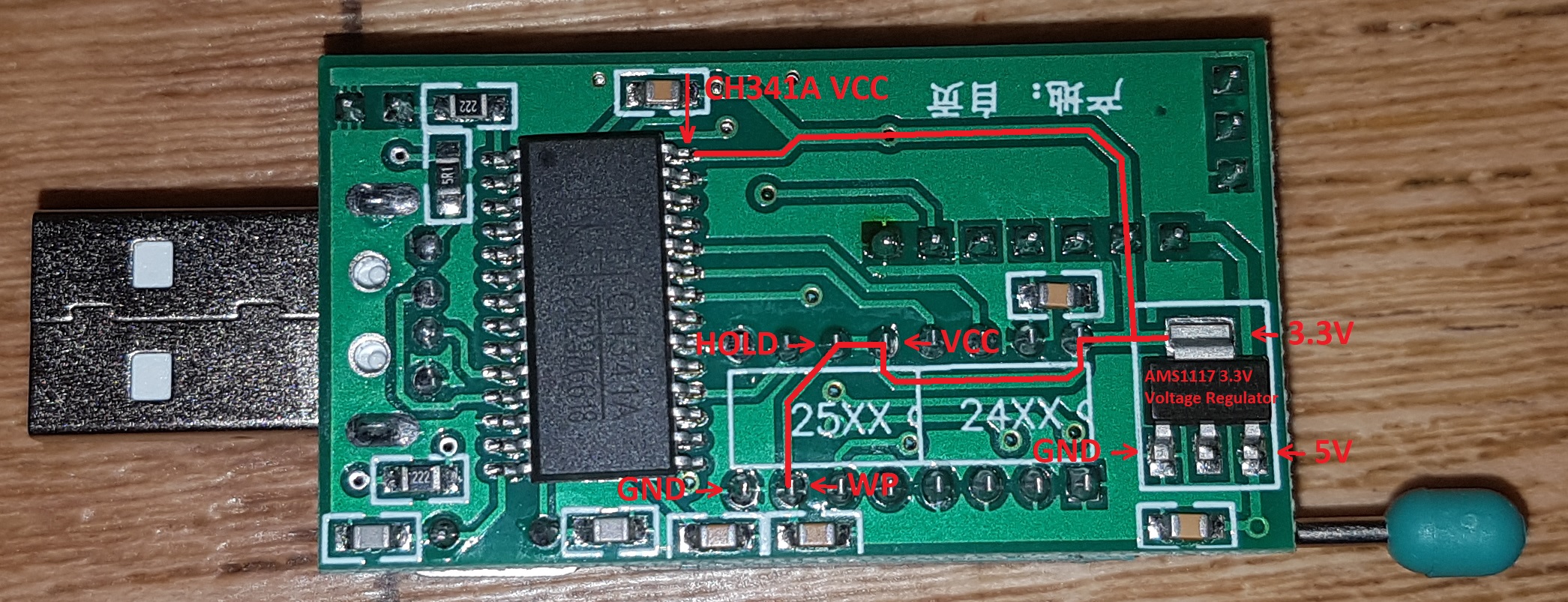
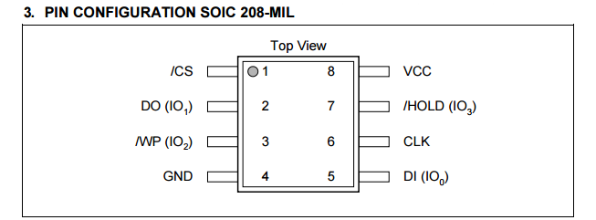
Pin Overview:
The voltage on CH341A VCC (5V or 3.3V) provides the same amount to CS, DO, CLK, DI
Edit:
About the MX25V4006E, it seems that flashrom has no specific support, but the corresponding MX25L and MX25V versions seems interchangeable.
From flashchips.h:
#define MACRONIX_MX25L4005 0x2013 /* Same as MX25L4005A, MX25L4005C, MX25L4006E /
#define MACRONIX_MX25L8005 0x2014 / Same as MX25V8005, MX25L8006E, MX25L8008E, FIXME: MX25L8073E (4k 0x20) */
From the Macronix driver:
#ifdef MX25V4006E
#define FlashID 0xC22013
(0xC2 is the vendor id and 0x2013 the chip id)
Thank you very much Wootever, your work is very appreciated !
I’ve used the the black PCB version (with Flashrom, because with the Chinese flash program I had errors with 1.18, 1.29 and 1.30) on a Winbond 25Q128FV1Q with success, although the flash was somewhat slow, it worked great.
I used it to disable the ME (Management Engine with) me_cleaner.
Since you said this programmer can fry some chips, I had ordered the green one you’ve linked.
edit: This is the correct placement of the chip in the ZIF socket: 
I have placed it backwards at first, and the chip and the programmer ran very hot !
I had similar problems with the CH341A Programmer software, there are also various versions available with some of them cracked or bypassed and without any official download source.
When looking for alternatives i stumbled across flashrom, which worked remarkably well. (I initially used a Ubuntu VM for flashrom, but that wasn’t very practical or portable.)
The slower speed might be a limitation of the WinUSB driver or even the CH341A itself.
The output pins of the CH341A (CS, DO, CLK, DI) are supplied with 5V on the black pcb version.
It seems most of the desktop mainboard 3.3V flashchips will tolerate the overvoltage, but it might be dangerous to other components if used with a soic clip on notebooks for example.
Indeed, some of the earlier CH341A Programmer versions had a wrong pinout picture.
Actually, this image was taken from the V1.18, it’s the newer version (1.30) that have a wrong image.
You can also see on the PCB it had the correct pinout engraved.
About the speed, the only version of the Chinese program that somewhat worked (v1.18) was even slower than flashrom, and it crashed a lot.
You are right, it seems the pinout has changed on the newer software versions, most likely to match the associated SkyGz CH341A programmer:

The generic CH341A programmers use the default pinout:

Small update:
I added a simple timer to compare the flashing process time between different chips or programmers.
Fortunately, the programming speed for the CH341A is identical on Windows and Linux.
Windows log:
Calibrating delay loop… OK.
Found Winbond flash chip “W25Q64.W” (8192 kB, SPI) on ch341a_spi.
Reading flash… done (in 1 minute and 4 seconds).
flashrom -E
Calibrating delay loop… OK.
Found Winbond flash chip “W25Q64.W” (8192 kB, SPI) on ch341a_spi.
Erasing and writing flash chip… Erase/write done (in 3 minutes and 13 seconds).
flashrom -w bios.bin
Calibrating delay loop… OK.
Found Winbond flash chip “W25Q64.W” (8192 kB, SPI) on ch341a_spi.
Reading old flash chip contents… done (in 1 minute and 4 seconds).
Erasing and writing flash chip… Erase/write done (in 56 seconds).
Verifying flash… VERIFIED (in 1 minute and 5 seconds).
Process completed in 3 minutes and 5 seconds.
Linux log:
Using clock_gettime for delay loops (clk_id: 1, resolution: 1ns).
Found Winbond flash chip “W25Q64.W” (8192 kB, SPI) on ch341a_spi.
Reading flash… done (in 1 minute and 4 seconds).
sudo flashrom -p ch341a_spi -E
Using clock_gettime for delay loops (clk_id: 1, resolution: 1ns).
Found Winbond flash chip “W25Q64.W” (8192 kB, SPI) on ch341a_spi.
Erasing and writing flash chip… Erase/write done (in 3 minutes and 16 seconds).
sudo flashrom -p ch341a_spi -w bios.bin
Using clock_gettime for delay loops (clk_id: 1, resolution: 1ns).
Found Winbond flash chip “W25Q64.W” (8192 kB, SPI) on ch341a_spi.
Reading old flash chip contents… done (in 1 minute and 5 seconds).
Erasing and writing flash chip… Erase/write done (in 58 seconds).
Verifying flash… VERIFIED (in 1 minute and 5 seconds).
Process completed in 3 minutes and 8 seconds.
I also added a function to disable quick edit on cmd.exe when flashrom is active to prevent accidentally application freeze which might corrupt the flashing process.
Researchers find almost EVERY computer with an Intel Skylake and above CPU can be owned via USB
I’m really happy to have disabled the ME.
Hi,
I have the Black Gold version of the CH341A.
I read that it does not operate at 3.3v and could fry bios chips?
I have a faulty bios chip on the Foxconn NT-525 netbox. Its a 8 pin soldered chip that I was told operates at 3.3v.
What is the easiest way to reflash it? Use a SOIC clip? Or should I just heat the leads up and remove it?
Heres a picture of the bios chip: 
Never done this before but it seems like a fun weekend project if anyone can help.
Please comment also on chip orientation.
Thanks.
The white mask on the ch431a adapter shows the orientation and pinning correctly.
The engraved dot on the chip is pin number 1.
See the link in the post #82 to fix the 3.3v for black ch431a.
You can try to flash with a clip adapter first, if this does not work you might need to resolder the chip.
On Post #82 it states that the Black CH341A due to improper design supplies the wrong voltage?? Seriously??!! Rather buy a new one than have to solder wires. Guess the green Ch341a is the one to get?
I read however that the jumper placement determines voltage setting such that pin 1-2 is 3.3v and pin 2-3 is 5v?
Been experimenting flashing onto a 25q64bvaig Winbond a P8Z68 Deluxe bios for testing purposes and after the 1.18 ver of software completes its flash the verification fails and says in disagreement…
Going to test another chip if I have one…
Thanks
Yes, it’s important that the supplied voltage on the CH341A (VCC) is identical with the voltage supply on the flash chip.
The green pcb is doing this correctly by suppling 3.3V to all pins:

This jumper only controls the flash chip voltage, the CH341A VCC is always supplied by the USB 5V which outputs it to CS, DO, CLK, DI on the flash chip.
Edit:
The jumper controls the CH341A mode (SPI or TTL), only the flash chip VCC is always supplied with 3.3V.


So the Black USB Ch341a is a piece of garbage and I should throw it out immediately?!
It seems to work correctly with most generic 3.3V DIP8 chips that can be put into the programmer socket.
However, it might be dangerous to some flash chips (and more likely to the components around it) if used with a SOIC8 clip adapter.
Edit:
Found another possible fix; cut the trace at the pcb back which powers the CH341A VCC with 5V:
(click here for bigger picture)
Then carefully scrape away the pcb coating of the 3.3V track:
(click here for bigger picture)
And solder it together with the CH341A VCC pin:
(click here for bigger picture)
Log from succesful test:
Calibrating delay loop… OK
Found Winbond flash chip “W25Q16.V” (2048 kB, SPI) on ch341a_spi.
Reading flash… done (in 16 sec).
flashrom -E
Calibrating delay loop… OK.
Found Winbond flash chip “W25Q16.V” (2048 kB, SPI) on ch341a_spi.
Erasing and writing flash chip… Erase/write done (in 33 sec).
flashrom -w random.bin
Calibrating delay loop… OK.
Found Winbond flash chip “W25Q16.V” (2048 kB, SPI) on ch341a_spi.
Reading old flash chip contents… done (in 16 sec).
Erasing and writing flash chip… Erase/write done (in 26 sec).
Verifying flash… VERIFIED. (in 17 sec).
Process completed in 59 sec.
@Wootever ,
Did you forget to solder a pin on your wire patch? The guide you linked that detailed the fix had a second solder point that I don’t see in your photo.
That’s for the V3 pin on the CH341A which should be supplied with 3V according to the datasheet, but it seems to work fine without.
The green pcb version also doesn’t supply 3V to this pin.
Hello to all, and apologies if this is not the correct format to ask for help in this specific thread topic.
I purchased an ASUS P8Z77-I Deluxe MB on EBay to use with one of my old 1155 processors. It would not POST using an i3- 3225 (one memory stick, etc.), so I used the on-board bios flashback button with latest Bios (1201), and it proceeded and indicated successful completion, just as ASUS details in the manual. However, it still would not POST with one stick of ANY of my known good RAM in either slot.
Googling led me to the cheap CH341A programmers. I bought a Black one before discovering this site and reading about the 5volt error. I used it to read the original MB BIOS chip (W25Q64BVAIG), but it will not verify. Successive readings are different, per file comparison with Beyond Compare. Re-soldering a few dodgy-looking joints did not change the result. So, I decided to buy the Green reader, and to also order a replacement BIOS chip, pre-programmed with the ASUS Bios ver1201 from EBay. The Green reader gives the same result as the Black one - non-verifiable (.bin) files. Note: I am using one of my Windows7 (64Bit) computers for all of the the CH341A work.
The new BIOS Chip arrived, and I was finally able to POST the P8Z77-I Deluxe, but I then had to work through MANY issues (repeated “New Processor” messages stopping the Boot process, Channel B memory slot not working and killing POST if populated, tweaking several bent and low socket 1155 pins, etc). Today I am very happy to have just gotten this MB working with all functions; passing MemTest, Prime95, etc. I have to assume that somebody corrupted the original BIOS Chip, but I don’t fully understand why I could not successfully flash a correct ASUS .CAP file, since I even went back to an i3-2100 to ensure compatibility.
So, the purpose of this note is to ask for suggestions as to how I can get the (Green) CH341A working successfully. Do I need to go back to a 32Bit version of Windows7?
I supposedly have Win7 (64) drivers in the downloaded folders, and the device shows up as working, and detects the chip, so I am puzzled why I get different results with each run.
Some earlier posts in this thread discussed some potential problems that could occur if the BIOS did not have the original MB Serial Number, UUID, and MAC Address. I have extracted the MAC and UUID from the old BIOS with FDD4, but it did not show a S/N. Note: The ME Version on the old BIOS is 8.0.4.1441 with BIOS ver1201. The Purchased BIOS is ver 1201, with M.E. ver 8.1.2.1318. I used the downloaded ASUS BIOS version 1201 in my Bios FlashBack attempts, so it probably worked, but the M.E. version mismatch might be the reason for not posting? The old BIOS Chip still does not POST in my (now) repaired system that works fine with the new BIOS Chip…
In summary - I welcome any suggestions as to how I can get the CH341A (Green) to read and verify. Can it just be that the old BIOS chip is trashed, and will not retain data?
After all of my work, I am unwilling to try to write anything to my new, working, BIOS Chip in the CH341 device until I am confident that it can read and write without corrupting the data.
P.S. The MEInfo tool gives me an error 9458, and will not run on this (now) working machine. Is this because of the ASUS BIOS .CAP format? I guess I need to buy some empty BIOS chips and play more with the CH341A?.. I will feel better making a clone of the working one to work with before entrusting it to the CH341A write process. And, yes… also before trying any “hot-flashing” methods. If the old chip is trash, a failed hot-flash would also leave me wondering what went wrong.
Thanks for any help!
@P8Z77
I would suggest to use flashrom for Windows instead, it has been proven as very reliable while also easy to use.
Extract flashrom_windows.zip and click on Install.cmd, it will install a CH341A compatible WinUSB driver and also opens a command shell to access flashrom.
Then, you basically only have to use two commands.
If the flash chip is correctly identified it will read the current chip content and save it as backup.bin:
flashrom -r backup.bin
This command will write the content of bios.bin to the flash chip:
flashrom -w bios.bin
Edit:
Here is the latest extracted BIOS for your mainboard (.cap -> .bin):
P8Z77-I-DELUXE-SI-1201.bin
Guys I found another usb programmer on Amazon called ‘Flashcat’. It seems to come with its own software and is at least 4X more expensive than those generic Ch341a usb sticks. Is this worth it?
https://www.amazon.com/Flashcat-Memory-P…45DH7GZ2V64N9R8
https://jb8a8f8.com/support/index.php?at…manual-pdf.526/
Thanks for the followup Wootever.
I loaded Win7 32Bit on a spare computer, and got the (green) CH341a programmer recognized.
When I run flashrom -r backup.bin on the original P8Z77-I Deluxe W25Q64BVAIG Bios chip, and then run verify, it fails.
Reading the chip multiple times, and then doing a file compare on the resulting .bin files using Beyond Compare, I get differences between each successive file.
So, should I assume that this original motherboard BIOS chip is somehow defective? Or is there is something in the Asus .CAP format that is protected(?) and just does not read correctly each time?
Can you suggest a reliable source to buy good W25Q64BVAIG chips? Having a few new good ones will eliminate one variable in this quest.
I have gotten to a working motherboard by buying a new "pre-programmed" replacement BIOS chip, but I want to make sure that I am not going to have future problems due to the lack of the original MB specific data in the replacement BIOS.
Thanks for any suggestions!