@Lost_N_BIOS i think i’ve followed your instruction but i still have the same error when using setup_var command : can’t set variable using efi(err = 0x00000008)
So to make a recap :
I can’t flash using H2OTTF because i get an error about secure bios protection
I don’t have Legacy boot mode in bios (the bios page is made by a single page where i can modify very few things like enable or disable wifi or fingerprint sensor)
I can’t enable legacy boot using setup_var
I can’t modify 0x17 which anyway seems to be already set to 0x0 (at least if reading that value using setup_var is ok)
There is an EFI folder inside my ME System Tools FPT folder but inside there is only a .EFI file. How can i use it ?
@tmbt - If 0x17 is already set to 0x0, which it shouldn’t be, but if it is then no need to change this, boot to however you can use FPT and flash BIOS region.
EFI file is used in the same manner I mentioned above for “boot to grub when no boot to EFI on exit page” Format FAT32, Put that file (The FPT one and fparts.txt) in all the folders, ways shown on the link posted above (But don’t rename, that’s only for the grub thing).
Along with this file, and then boot to USB - https://github.com/tianocore/edk2/raw/ma…l/X64/Shell.efi << This, you make copies of, some renamed Bootx64.efi, and put like I showed in the images linked here >> [Help needed] Hidden Advanced menu Bios HP Z1 J52_0274.BIN (2)
Go ahead and copy the FPT.efi and fparts.txt to all the same directories too, to save hassle from having to switch folders or reboot to copy to another folder and try again. Then follow this general example of how to get to correct folder within shell to run FPT - https://justpaste.it/FlashBiosViaUEFI
None of that is necessary though, since you’ve already ran FPT before, run it same way now and flash BIOS as mentioned >> FPTw.exe -bios -d biosregm.bin
This should be no problem since BIOS lock is disabled, if it really is, if not you’ll get error 368
Back to H2OFFT - you get this error using command line as mentioned? If so, try again with the GUI and edit platform.ini >> EnableFlashSecureBIOSOverride=1 (Add this, or change it to 1 if already present, default is zero)
Never mind on this, what was here (about vars), we’ve already been this route 
May have to give in and order a CH341A flash programmer and SOIC8 test clip cable and wait for delivery. BUT, I think it should be possible via FPT though (Same way you ran it before), if BIOS lock is indeed disabled already, so there is hope!
@Lost_N_BIOS Sadly the bios is not unlocked. I got 368 error when trying to write using FPT.efi -bios -f so it seems that our last chance is the CH341A flash programmer and SOIC8 test clip cable. Am i correct?
Where can i buy them and what skill do i need ? I don’t want to mess with my motherboard. Is a difficult operation ?
EDIT : I saw where to buy and how it works. Are you sure that the test clip cable is going to work on a laptop motherboard ? It seems so thin i’m not sure i can attach the clip cable to the bios chip
EDIT2 : Is this the right chip ? It would be awesome because it’s quite easy to reach and there is no need to remove the motherboard from the laptop chassis.
Thanks
Mattia
Yes, as I suspected. Maybe not last chance, keep trying to get setup_var to change 0x17 to 0x0. I know it says that now, but try setup_var2 and setup_var3 method, have we discussed those yet?
They’re created for these issues, here is both files, only use one at a time and each only use the var2 or var3 per the folder it’s in
http://s000.tinyupload.com/index.php?fil…762783500916238
Same way >> setup_var2 0x17 0x0
>>>>>>>>> setup_var3 0x17 0x0
Then try FPTw.exe again from windows, or DOS, however you used previously
Yes, it’s simple to use, and yes it works on laptop (Desktop is same BIOS chip) here is a guide with plenty of images
[GUIDE] Flash BIOS with CH341A programmer
Unsure if either of those are the BIOS, you’d have to dump them before we could confirm. Top one is more likely the BIOS, other smaller probably EC or ME
@Lost_N_BIOS
using sutup_var2 i’ve 5 matches for 0x17 variable and one of them has 0x01 in the variable. How can i modify that one for sure and not the other 4 ?
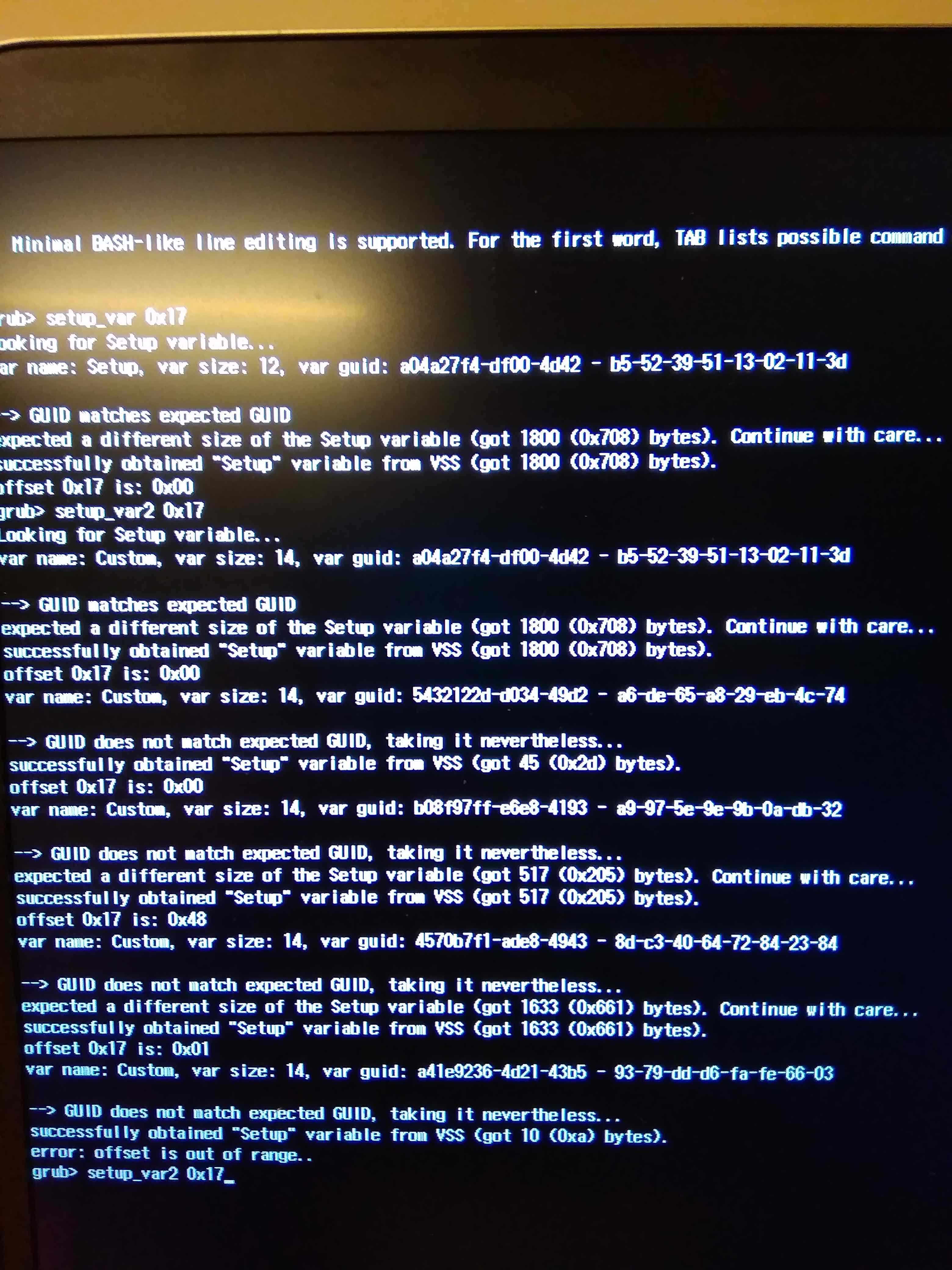
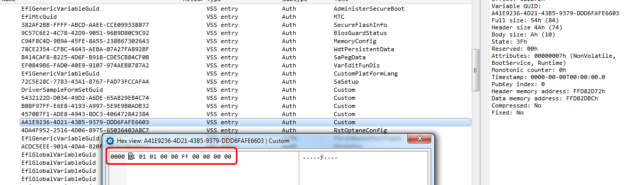
@tmbt - It doesn’t look to be correct, unless it’s just incomplete? See, here is from one of your original vars, and there is no 0x17 in this GUID, it only goes to 10/0a, but maybe it’s incomplete
[02A] “Custom”
GUID: A41E9236-4D21-43B5-9379-DDD6FAFE6603
Attributes: 0x7
DataSize: 0xA
Data:
00000000: 01 01 01 00 00 FF 00 00 00 00
We can change that using vars, but first we need a complete dump of this GUID. Lets see if we dump it by itself, if we can get a complete dump of this GUID
H2OUVE -gv customnewsingle.txt -g A41E9236-4D21-43B5-9379-DDD6FAFE6603 -n Custom
@Lost_N_BIOS
Sorry for my late answer but i got a lot of work to do. Here is the copy paste of the text i got using the command line you gave me :
1
2
3
4
5
6
7
8
9
10
11
12
13
14
15
16
17
18
19
20
21
22
23
24
25
26
27
28
29
30
31
32
33
34
35
2
3
4
5
6
7
8
9
10
11
12
13
14
15
16
17
18
19
20
21
22
23
24
25
26
27
28
29
30
31
32
33
34
35
************************************************************************************
Insyde H2OUVE (UEFI Variable Editor) Version 100.00.16.08
Copyright (c) 2012 - 2015, Insyde Software Corp. All Rights Reserved.

#************************************************************************************
#  Please follow file format to modify variable information.
#
#  File Format:
#
#   [Index] Variable Name
#          GUID: XXXXXXXX-XXXX-XXXX-XXXX-XXXXXXXXXXXX
#          Attributes: 0xXX
#          DataSize: 0xXX
#          Data:
#                00000000: XX XX XX XX XX XX XX XX XX XX XX XX XX XX XX XX
#                00000010: XX XX XX XX XX XX XX XX XX XX XX XX XX XX XX XX
#                 .....                         .....
#
#  1. Index is a number in Hex.
#  2. The number of data must be equal to datasize.(Except datasize = 0)
#  3. "X") represents a hex number.
#
#  Delete Variable:
#    Please modify datasize or Attributes value to zero.
#
#************************************************************************************

 [001] "Custom"
      GUID: A41E9236-4D21-43B5-9379-DDD6FAFE6603
      Attributes: 0x7
      DataSize: 0xA
      Data:
            00000000: 01 01 01 00 00 FF 00 00 00 00
Let me know what you think about it. I can still buy the equipment to hardware dump the bios and programming it back
Mattia
I thought maybe that would be it, that’s all that’s in that GUID, not enough entries there for what’s shown in your image. Unsure if that means the image is wrong variable, or incorrectly detecting some other variable
Will it change if you tell setup_var2 to change them all, or does it spit back same info and that one is always 0x1?
@Lost_N_BIOS I tried to update that var using setup_var but i received the usual 0x0000008 error.
I think at this point my last chance is to buy the tools you told and try that way. Do yoi think is possible ?
Thanks again for all the support!!
Mattia
@tmbt - so I checked this GUID itself, in the BIOS, and the output we’re seeing is correct, it’s only 10 bytes long, so whatever is shown to you by setup_var2 is either incorrect info or it’s giving the wrong GUID. See image below
You’re welcome. And yes, with the programming tools, we’ll have no issue, we can change anything we want to anything we want! 
Ok,
i’m going to buy what you suggested in a previous post and will update this thread when i have them
Thanks
Mattia
@Lost_N_BIOS Hi,
the programmer and the cable arrived yestarday. I would like to try to dump the content of my bios but first i’ve a (stupid) question.
My bios chip is soldered on the motherboard so i will use the cable to connect it to the programmer. During this operation should i disconnect the laptop battery from the motherboard or i can leave it connected?
Thanks
Mattia
@tmbt - It’s not a stupid question, it’s a good one!  All systems are different, some may need the battery or power connected, others may work fine without it.
I would remove battery and power at first, then if it’s not working no matter what add battery, then if still not working plug in main power.
What BIOS chip are you working on? Please check with magnifying glass and flashlight if you need to
Here is guides for using these, first one has plenty of images so you can get it all connected properly
[GUIDE] Flash BIOS with CH341A programmer
[Guide] Using CH341A-based programmer to flash SPI EEPROM
[GUIDE] The Beginners Guide to Using a CH341A SPI Programmer/Flasher (With Pictures!)
Please do not write anything until you’re 100% sure your dump is verified and valid. Valid means your opened it in BIOS tools and it looks similar to a stock BIOS, and you checked in hex before that to make sure it’s not all FF or 00
If you are not sure how to check this out, upload your dumps and don’t try to write anything until someone says dump is proper and it’s OK to write.
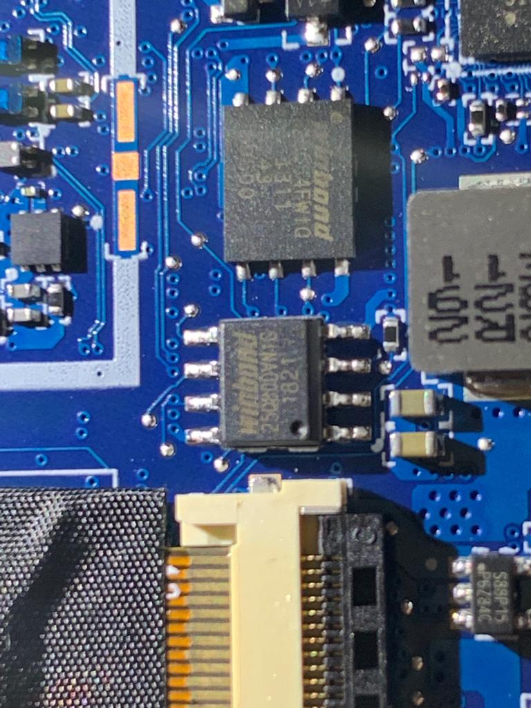
@Lost_N_BIOS This is a never ending story  … I’ve connected the programmer and then the cable to the chip on the motherboard. If i try to read the smaller chip (i’m referring to a picture i sent you on page 2 of this thread) i can dump the content of the chip but it 's not the bios . After some Kbytes of 00 there is a reference to a Texas Instrument DP controller or something similar.
The problem is that the other chip is not thick enough to be catch by the pliers so i 'm not able to dump that one.
Is this possible ?
What can i do ?
EDIT :
Seems like the W25Q64FW is using 1.8v instead of 3.3v but i don’t have the 1.8v adaptor. Is this the reason why i can’t read the chip ?
@tmbt - As mentioned that smaller one is probably EC. Show me images of the entire board, that larger one above the tiny one, doesn’t look like BIOS now that I look at it again (it looks surface mounted like memory, instead of having legs)
And yes, if BIOS is W25Q64FW that is 1.8V and you’ll need adapter to use with the programmer, like this
https://www.ebay.com/itm/202046860676
Sorry we did not notice this earlier!!
@Lost_N_BIOS ,
Hi attached you will find all the pictures (EDIT … pictures are in two posts later) i made this morning on both sides of the motherboard. I cannot spot anything similar to a BIOS chip but i hope you will be more lucky !
I was able to find a 1.8V adaptor here in my city without ordering over internet so i’m ready for everything now  …
…
Please let me know !
Thanks
Mattia
UPDATE: i tried to dump the content from some chips on my motherboard but the only one detected and readable is the first one. All the others are too thin and the clamp cannot reach the “legs” of the chip in my opinion.
Heeeelpppp!!
@tmbt - reat you found a 1.8v adapter locally, that’s pretty cool it’s even possible to find one without ordering (Are you in China?) I thought you already connected to W25Q64FW before, no?
Please put all those in a zip folder and upload somewhere, thanks. Once I can see all the images I will let you know if I can find. Sorry don’t want to look at them like that, I’m on limited internet and there’s no reason for all those not to be zipped
@Lost_N_BIOS No i live in Florence (Italy). I was going to orderning it on eBay but then i noticed that the seller was from Florence too so i called him and arrange the pickup at his home …
About the W25Q64FW no i wasn’t able to connect to it. I was only able to connect to the small chip (which is only 1MB so i guess cannot be the bios) but inside the dump there is reference to Texas Instrument Controller. That’s the only chip i was able to connect. All the other chips i tried seems to be too tiny and the clamp doesn’t reach the pins (at least i think this is the problem).
Here are all the pictures in a zip file : http://s000.tinyupload.com/?file_id=03192282629654589523
@tmbt - That’s cool you were able to locate so easily! Yes, the 1MB isn’t BIOS, probably? Not sure, send me the file so we can confirm.
thanks for images, I will look them all over and let you know what I think tonight. Pre-tonight, I checked and these are very small resolution, can you zip larger ones? If these are only size you have it’s OK
* Edit - from what I can see, yes, looks like the one above the one you already dumped is the BIOS.
If you cannot get clip onto that, and you aren’t good at soldering, I think only way may be similar to what’s done here, but we’d need to find exact method for your model
Dell Inspiron 5520 BIOS recovery help needed
Tonight I will try to find schematic and see if I can find method for your system.
@Lost_N_BIOS : No i’m definetly not good at soldering so i would like to avoid that. I tried more than once but i cannot get the clip on the chip. I think it’s the chip because from reference manual it is 8MB size and the dumped bios i made was 8MB. How could be the 1MB chip ?
Here are the HiRes pictures (50MB totally) :
http://s000.tinyupload.com/?file_id=56999608203395172731
http://s000.tinyupload.com/?file_id=07978419008889851887
http://s000.tinyupload.com/?file_id=60421646517801435154
You’ll need all the 3 files …
About the link you posted i’ve read it twice but i don’t have the slightest clue of what you’re talking about in that thread ![]()
Mattia