It could be the clip then, or maybe a partially faulty BIOS on there, but not on all three of them at same time. Can you desolder or no?
I cannot desolder. I’ve tried a different programmer and cable but the result seems the same. I’m investigating on the possibility to rebuild uboot from source - the source bundle is available at http://opensource.dell.com/releases/idrac8 (iDRAC7 2.x shares the same codetrain of iDRAC8)
There’s also some clue on the SPI flash layout here https://github.com/Fohdeesha/idrac-7-8-r…r/Flash-Map.txt
Should be possible to rebuild or correct the current image, or from source you linked, using that layout if it’s 100% correct
I’m wary of flashing the image I’ve rebuilt onto the board with failed iDRAC due to the risk the flasher will fail to write the same way it fails to read. I am also sufficiently doubtful about this being an issue related to a broken u-boot - IMO this is due to a broken MMC.
The opensource package from dell includes all that is needed to regenerate firmimg.d7, but not the source of u-boot, which instead seems to be provided in binary form. I’m inclined to believe it is still possible to break u-boot but I have yet to figure out the keys and timings.
Since you have programmer, it will be OK, it’s already failed and you have a backup image of the failed chips contents, so you can’t loose anything by trying. But yes, there is what you mentioned, not being able to get a consistent verified read, so write will probably be the same until you can get that sorted out.
I tested your exact programmer and that chip MX25L3206E, with the version of software and CHIP ID selection I mentioned previously, so we know that works. If it continues to fail for you, fail in a “verify” way during programming, not fail to boot/work, then we know there is an issue with your programming process somewhere and not a problem with the chip/programmer/software. Of course, knowing if the new image works or not is another issue, only someone else with one of these can test, or you can test on another working one provided you can backup it’s chip contents confidently enough to erase/reprogram that with your new image.
Just ordered a kit to modify SOP8 chipset, did the same upgrade to latest 2.x version and bricked the motherboard on a R620.
Will let you know how it went!
Just curious if anyone was able to figure something out, just ran into this same issue
Thanks for the update, I just fell into the same hole that @kwaleeb did…step by step, in the same exact way…it was pretty funny (you have to laugh) that I succeeded then failed in the same manner…it was kinda sad, kinda funny…what can I say. The fix is “easy”, if I can find a way to get the 1.66 bios flashed on the idrac7. In case it helps, below is the link to the correct update path. I have the file that should bring this thing back to life, but no means of flashing it.
https://www.dell.com/support/article/us/…e-path-?lang=en
Update Path for iDRAC 7
If the iDRAC firmware is still running on a version between 1.0.0 and 1.57.57, follow these steps:
Update the iDRAC to version 1.66.65, which is the last one separated from LCC firmware
Next version to install is 2.10.10.10, the first one with combined LCC and iDRAC firmware
Now update to latest version provided on the Dell Support webpage (Section 1 of this article)
There are tricks which can work around the need to use a chip programmer, which is kind of hit and miss at least in my experience, as long as the SPI chip is functional. Said tricks are however covered by a NDA as Dell is working on an update that supposedly fixes the security hole revealed by iDRACula - and credit for them goes to fohdeesha. The next iDRAC release is estimated to happen around December/January, I’d expect them to become public after that.
So… Use PM and threats to secrecy 
So I just updated the replacement r620 from < 1.47 to 2.60 and used HTML5 console.
As was written here earlier the path is
* Do every step up to 1.66.65, in my case, 1.46, 1.57, 1.66.65.
* Update Lifecycle from every step up to 1.4.2.12, in my case 1.3.1.13, 1.4.0.128, 1.4.2.12.
* Update BIOS to the latest every step. I chickened out here and updated every step, there may be better paths.
* Install Lifecycle in the following order
** 2.10.10.10
** 2.15.10.10
** 2.20.20.20
** 2.21.21.21
** 2.30.30.30
** 2.60.60.60
Now, under virtual console you can choose type of console, pick HTML5.
When choosing what to download on dell.com, choose the win32 exe, upload in iDRAC
Except for BIOS, I just downloaded the standalone EXE and used unzip to unpack the image inside.
Now I have to wait until the 12th for my kit to arrive so I can test this out on the broken MB.
bios update should be fine, looking forward to hearing from you on this!
A few flashing and servers later, I believe that stepping through each firmware is paranoid, albeit justified. I have not had issues in bringing the server to 1.66.65 for iDRAC and the latest 1.x BIOS, then upgrading iDRAC to 2.10.10.10 and the BIOS to the earliest 2.x available. Once at that point, it becomes possible again to use the Lifecycle Controller, which updates straight to the latest and greatest available for both.
I’m also struggling with a dead IDRAC but on a T620. I’m struggling to find the UART connections – any chance you could post a pic or describe where they are on the motherboard?
I don’t have a system like that, but you should still be able to find 4 pins aligned around the area where the iDRAC connector and its CPU are.
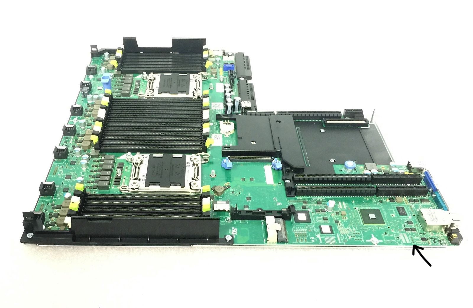
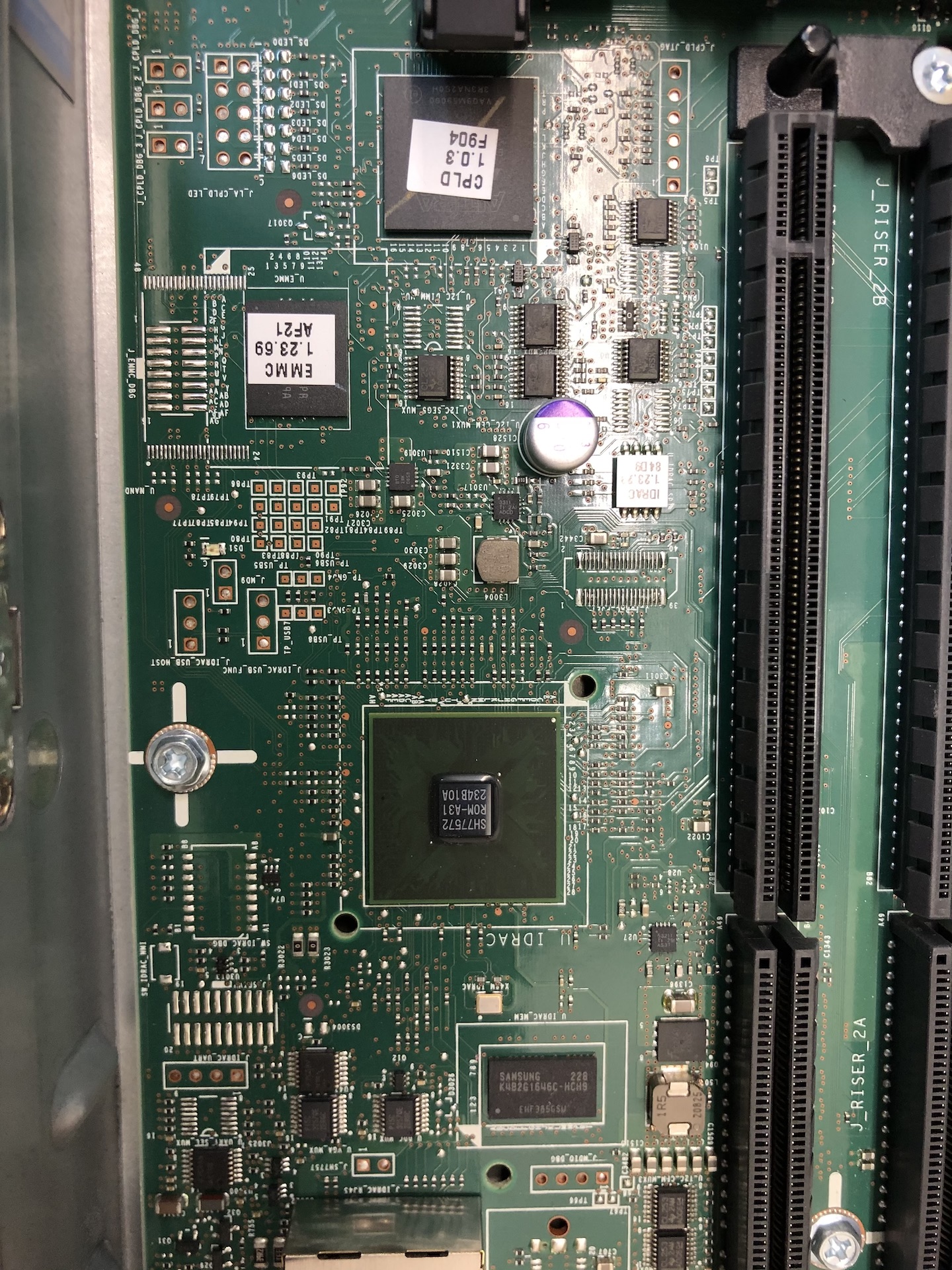
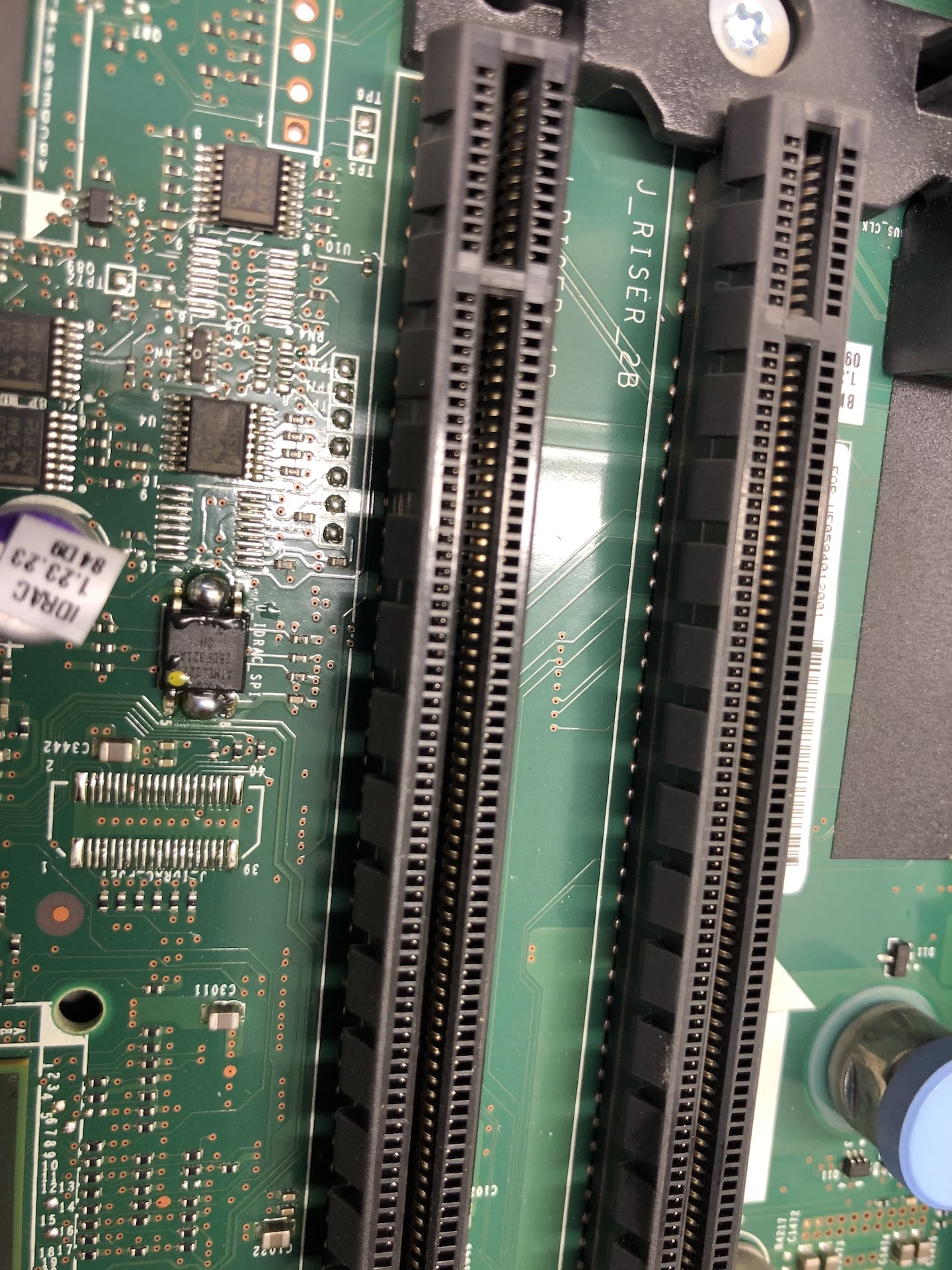
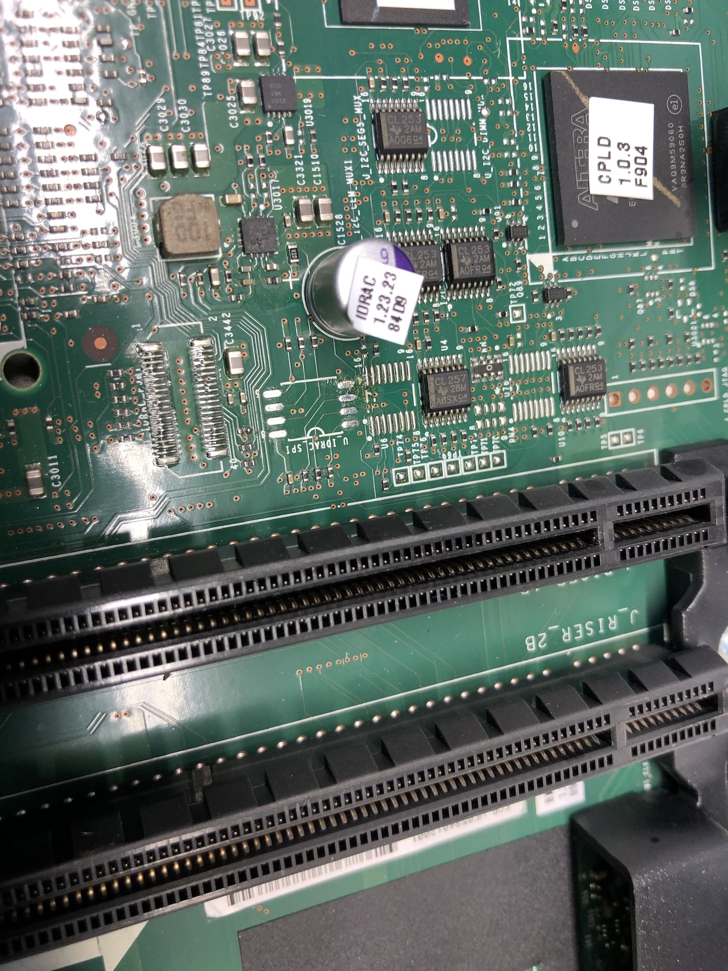
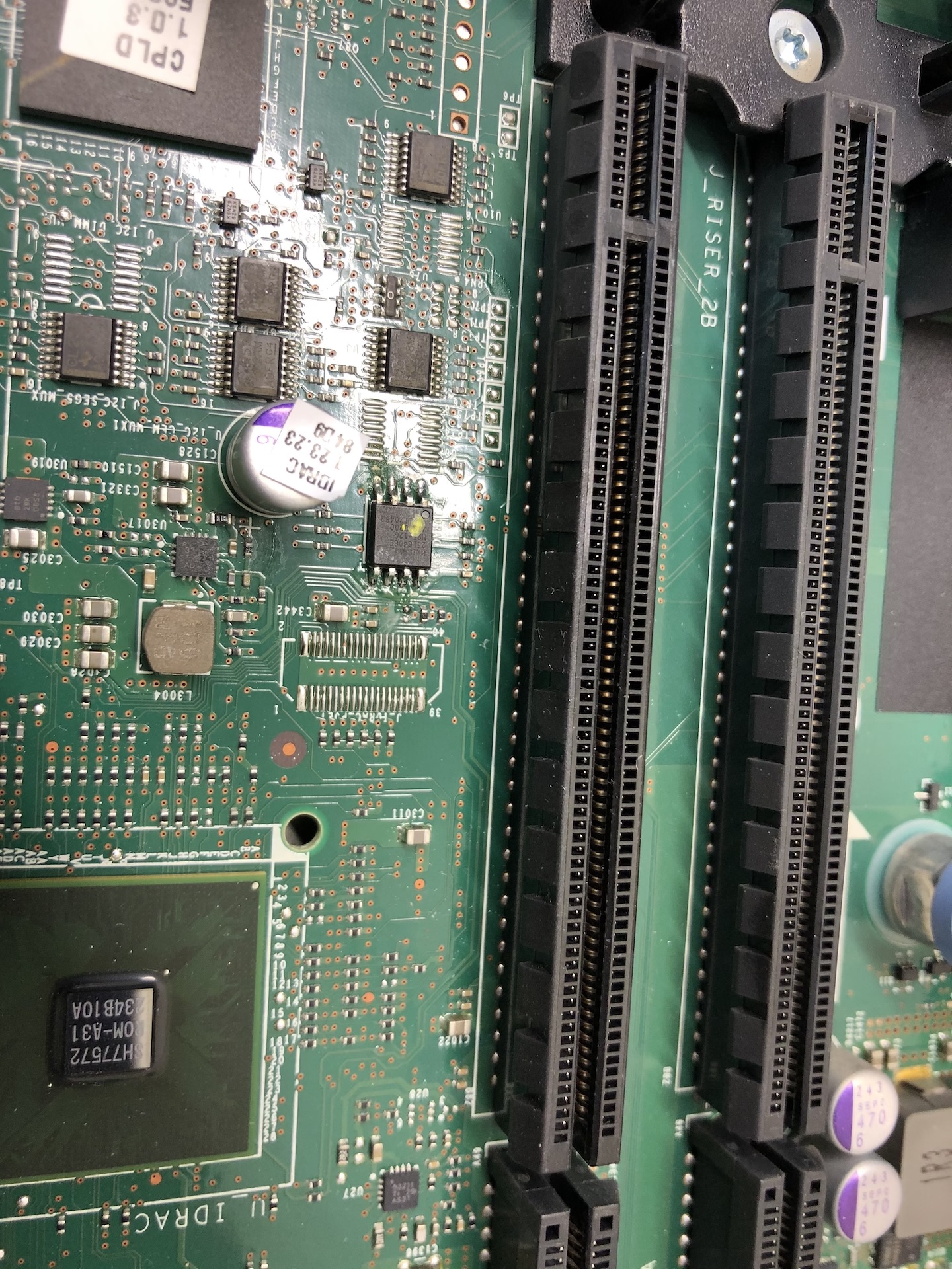
Hi. I also have an iDRAC initialisation error on my R620 server. Bricked it yesterday on attempt to update FW. Take a look on this picture, I marked the position of UART interface on the MB. They didn’t soldered any connector, and I think I’m going to solder there 4 pins to be able to connect.
Hi. Two days ago I have done an experiment. I soldered out the 25DF321 FLASH memory of the iDRAC and tried to read it out using a programmer. To my surprise it was completely unreadable. Moreover, the programmer wasn’t able to recognise the type of the IC. At this point I looked at my warehouse for some old motherboards and found that some of them have a 25L64 FLASH memory as a BIOS chip. Which is suppose to be exactly the same as 25L32, but it has a twice as much memory. So I soldered it out and was able to write into this chip the R620 iDRAC dump (Nannerkins provide it to us in some of the previous posts). And soldered it into to the server’s board. Now when power was connected to the server, iDRAC’s indicator lamp on the back panel started to blink constantly with an amber light. My first thought was that I solved the problem and it just might need to make a reset to the iDRAC because before I changed the chip iDRAC was bricked completely, and there was no light on the back panel at all. To my disappointment it wasn’t true - iDRAC still does not respond to long press and the amber light continues to blink.
My next steps would be:
1. Try to use exactly the same FLASH type(25DF321) which I have already ordered from EBAY
2. Try to find another R620 and read the memory dump out of it.
3. Try to connect to UART interface and see if there any activity.
Below you can see some pictures describing desoldering an soldering process
What software did you use to read/write the 25L64 and what is it’s full name? If it’s W25L64FV (Choose BV and use software 1.30, if BV try FV instead)
Its full name is 25L6406E. I have a USB MiniPro Universal programmer. You can find it on EBAY. It has a pretty large list of supported chips.
As for FLASH itself, I prefer to wait until I’ll get 25DF321A and a clips socket adapter for in-system programming that I ordered and give it a try again. Moreover, it might be that I’m going to get the access to another R620 server to read out iDRAC BIOS. I think it will be much better to try this first. PCB don’t likes multiple soldering/soldering, and there is no option for SOIC8 adapter that can be installed between PCB and IC to allow the installation without soldering(ike you have it for ICs with DIP body type).