[Request] Lenovo P360 BIOS CPU Support for Intel 13th Gen

Exactly, so now I disabled ME by setting that AltMEDisable bit so that I can write to -BIOS using fptw64 now.

Is this wrong? I now have RW access to BIOS when I didn’t before, so I don’t understand what’s wrong. This is the only way I was able to figure out getting write access to the FD/BIOS region.

Sorry, maybe I just didn’t explain it well before. On stock BIOS, I had read access to everything; DESC, ME, BIOS, GbE. I did not have write access to anything even though I thought I did.

I’d like to make a point that I did read the main post and a good portion of every thread you have linked me, I have spent the past few days learning about this stuff.

Ironically, the best detailed stuff was from a random github repo that explained using ifdtool to set the needed bit to write to FD and disable ME.

Its nice being able to make it this far by myself, I’m looking forward to attempt the microcode mods.

I have opened the BIOS update files for the new workstation with 13th gen support in UEFI Tool NE and the only thing that worries me is it has some extra microcode revision/ids that aren’t present in the microcode thread, like for some additional 13th gen CPUs I am guessing.

platomav/CPUMicrocodes: Intel, AMD, VIA & Freescale CPU Microcode Repositories (github.com)

If they are newer than the ones here…that i doubt it…,report it here and attach them.

EDIT: Ignore MCExtractor ext. info… do you see its physical offset location? This is the mcode.
You see it in UEFItool or AMI MMTool, period.
You’re not obliged to provide your dumps as its contains the system personal data, but i dont have one from that machine to work with and do tests, i do not provide mod files unless i know for sure that they work or that the motherboard has a BIOS Flash Back feature to recover.

Hello,

I am a little confused on the output of MCExtractor. When I view my BIOS with UEFI Tool, I see the two microcodes I am expecting:

However when I use MCExtractor, I am getting 5 output files in the view:

Where did these extended bins come from and the microcodes inside them? This is making it very confusing on which microcodes I need to try and fit in my BIOS.

@MeatWar I think I modded my BIOS correctly! I am trying to flash it now to test, and I am getting the below error:

I thought with Intel ME disabled I would be able to write to BIOS? You can see in my earlier screenshot in this thread that ME is disabled.

Regarding your edit (I miss them sometimes as its not a new post) I used MMTool to add the microcode from the CPUMicrocode repository and (I believe) it was added in the same volume without issues as there was enough volume space.

It just isn’t letting me flash and I don’t know why, I thought disabling ME would enable write for the BIOS.

First of all, i dont know what you’re flashing (26MB??? bios region only…?) or what cmd used…

I did told you to test it, writing right back the bios_region dump, in ealier post

fpt -bios -d bios_region , will retrieve a dump of bios region
If FD grants write access, this previous dump: fpt -bios -f bios_region

If these 2 operations were successful, then we know that FPT can write/flash the modded bios_region you dumped and performed the mods.

image

Read it to understand it…

And dont ask me about “ifdtool”, no expertise with it whatsoever.
What you’re trying to achieve i have no similar system or yet done similar operation in such HW generation… with such modern Bios(AMI v2 protected ranges)/ME16.1, just to let you know…

EDIT: Then if after that “AltMEDisable bit change” still cant write the bios region. its still OEM locked. Research it on the forum or outside for similar operations… i dint thought this would be easy and you shouldn’t also.
Make new posts/requests on specific/isolated operations/issues and wait for other users help.

Pont B of the linked guide show us the bits… in earlier hw generations i know that some users edit them in ME package tools/FIT tool…but this the latest 16.1 …

There were bios with BIOS Lock, CFG Lock etc… in hidden menus, these were also used.

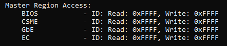
EDIT: No… not useful on your operation, BIOS REGION MASTER ACCESS (fpt -i report), this is what we want.

I did read that and tested it, but I tested write access to FD by using fptw64 -DESC -f FD.bin and that worked, I thought that’s what you meant.

Because following that thread, I can dump my full image with fptw64 -d spi.bin and I can dump the respective BIOS, ME, and FD regions as well. After doing the AltMEDisable bit change, I can now write the FD region, but BIOS cannot be written.

In that guide you linked it mentions specific sections that have OEM protections but doesn’t say how to resolve them; im attempting to look through the BIOS now to see if there’s any hidden menus.

I found something!

I found this Enable/Disable Me FW Image Re-flash text but it looks like a statement rather than a menu option I can enable? In that other guide, its an One of Option with desabled and enabled values but here it looks like a statement and I don’t see any values to enable it… Any thoughts?

And thank you so much for your help so far.

Ughhhh I feel like I’m so close! Nothing in this menu regarding BIOS Region Master Access. Can I upload this menu txt here and would you be able to see if you find anything of note?

WAIT!! IS THIS IT?!

Here is that output:

Not sure what disabling ME even did since it only let me -f on FD/DESC, what use is that lol… I am so confused what I should be doing.

I was attempting to flash BIOS only and that’s what was giving me that Protected Range Registers error in my previous post.

@MeatWar Can I send you the BIOS file in a PM and can you help me find the Flash Protection Range Register option? Using IFRExtractorLS its showing as offset 0x73A and using IFRExtractorRS its showing as offset 0x73D. However when I boot to an efi shell and read these offsets, they both have a value of 0x00. I think they are reading the BIOS incorrectly, it should be enabled and I want to disable it.

No my friend sorry, nor to you or anyone else, i have no time for this kind of issues and it takes a lot of time and research… smaller requests ill do it once in while…or do you think that my already contribution to this thread was not enough at spending my time???
Stick with the linked guides (Very well elaborated and plenty of info…more than expected from users POV) and do a deep reading of it, search similar situations on the forum, search specific words on search box on the forum etc…

Im not an ALL ROUND GURU on all subjects, i only provide my point of view of each issue and my opinion, general help to forum users.
As i already told you, post new requests in specific threads related to specific issues/achievements.

Good luck, all the best.

Hello @abhorsen ,

The new machine with 13th gen support will probably be the same board. I’ve seen that before with Lenovo. They love to milk it for all its worth.

You may be able to flash the “new” machines BIOS when it comes out.

Best regards,

-68k

@68k-dude

I already have the new BIOS, its available on the Lenovo site. That’s where I found the microcodes to add to my BIOS.

I already have my modded BIOS ready to flash, its just the Protected Range Registers that prevent me from doing so and setup_var modification doesn’t persist for VarStore variables, flashing in the EFI shell while the variables are changes throws the same error, so there is something locking the BIOS from being flashed.

Hey abhorsen,

Sorry I will not be much help, but I started a few weeks ago exactly the same thing, but for the P340 (M90q), it has a Q470 chipset, so it should support 11-gen CPUs but of course Lenovo did not provide a microcode update for it.

However, I started in a completely different way, mostly because in the past I’ve successfully modified a bios of a Lenovo M900 and put an i3 9100 in it.

What I have done so far:

  • At first I did some dumps of the BIOS chips (because it has two) with the removal of the CMOS battery. (these dumps were OK, but the UEFI editing tools have seen them as corrupted)

  • I ditched this idea, went with your way with the FPT. I got the exactly same results as you, however I found that my machine has a dedicated jumper to disable ME, so it was not needed to fiddle around with the sound chip. With the disabled ME it was possible to dump all the BIOS regions but of course it was not possible to write to BIOS, due to the Protected Range Registers.

  • Today I did some dumps (5 consecutive all five were the same) with the CMOS battery in place, before that I’ve resetted the BIOS to defaults as before with my first attempts, but this time the dumped data was different from my previous dump.

  • What is interesting (though I guess it is normal, that the software based dump from the FPT and the hardware dump with the CH341a are different, the software based contains more info and completely editable/readable by all the UEFI modding related tools, but the size is the same)

  • I’ve prepared a microcode modded BIOS file from the FPT dump, and would have tried to flash it, but unfortunately my junk SOIC clip just broke and I have to get another one.

Been a few months and haven’t seen a reply. Anyone get any further?

Yeah, I’m interested if anyone has found a solution for this too, specifically for the P360 Ultra. I have no experience whatsoever in bios modding so I’m also wondering – what is the likelihood of this happening?

Personally, I would think that unless the BIOS (region) for the P3 can be crossflashed to the P360 without modification (or only with minor modifications), the likelihood of it working is not very high. This is assuming the motherboards for the P3/P360 are similar if not identical, and the Boot Guard plays nice with the mod. A hardware SPI flasher is likely needed as well, in addition to splitting/stitching the dumped contents for flashing.

I have tried adding 13/14gen support on my DFI ADS310 (LGA1700 as well, not a Lenovo), and originally the board has a BIOS version dated Sep 2022 with an earlier version of ME V16.1 and microcode for only Alder Lake. I updated/added the ME and microcode to a recent version, and while it POSTs with a 14700K, the BIOS cannot detect the stepping of the CPU, and most importantly any PCIe associated with the CPU directly are non-functional (first and only x16 slot and first NVMe slot out of 2), and the drivers for UHD770 cannot initialize in Windows. It appears that a recent ME firmware and new microcode may not be sufficient conditions to bring full support of Raptor Lake to an older board.

I would believe the ADS310 is already close to an ideal case for such a mod, where there are no boot guard (Manufacturing mode is still enabled), only one SPI chip that is also socketed, and the AMI BIOS appears to be as vanilla as you can get. Lenovo probably would not add new mechanisms to the older P360 BIOS to enable support while possibly holding back just the microcode for Raptor Lake. There is probably something else in the P3 BIOS that the P360 BIOS lacks, in addition to the ME and microcode, that is necessary for full 13/14Gen support.

Probably someone needs to find out if there are additional modules necessary for 13/14Gen support, because it really seems that just updating the microcode and ME to the latest versions isn’t enough, unless you are okay with forgoing PCIe/NVMe slots and probably even the integrated graphics, or whatever other issues the Lenovo flavor of BIOS comes up with.

Of course, what I said comes after being able to flash the BIOS image into the separate ROMs in the first place, which seems like where OP is stuck at.