Hello i have do HDA_SDO pinmod for have the complete bios ,i have mod it, it’s ok but when i do write i have the error i have error 280failed to disable write protection for bios space.
i try afudos /gan but it’s impossible it’s not reconize the chip bios.
I have try spi programmer with clip but it don’t reconized the bios chip.
It’s an intel AMIBIOS 4.
with the pinmod , now my sound card doesnt work anymore
thanks
Welcome to the forum (I am new too, however I too am glad to help).
In general, you cannot flash modified Intel .BIO files, due to Intel’s security checks (I too have an Intel motherboard, the DH55HC), this I was told by @Fernando , and later saw in this thread (you’ll have to read a few pages to understand the situation properly), however you can dump your bios with and mod it with a serial programmer (CH341A is recommended) and then (after backing up the dump), mod the dump and flash it by means of the programmer.
I personally wonder whether I can dump my BIOS by means of the serial connection on my motherboard (that would be fun, using the host DH55HC to program it’s own SOIC chip, although I do not think I’ll go so far as to flash the modded dump).
By the way, is your BIOS fully updated? If not, it’s best to first update it to the latest version, before attempting any sort of modding/programming/etc…
yes it s the latest bios in the mainboard , i have dump the complete bios with fpt , but the mistake is to write it
I have am not yet sure whether you can dump the BIOS from within then OS (that is something I still have not understood), however you cannot flash the modded dump via standard software, only via the programmer.
How did you try reading the chip, was the DQ77KB the host PC, or were you using a second computer to read the chip’s data?
Update: Feel free to answer, though I won’t be available for the next 30+ hours or so, hopefully others with more knowledge than me will help out.
i have try with mini programmer with an other pc with a clip witout desolder the chip but they are two chip and the mini programmer doesnt reconize the bios chip. , i have dump with FTP with the os with HDA_SDO pinmod it’s ok for read all the bios but error for write
When you say that the programmer doesn’t recognize the chip, do you mean that it recognizes the chip’s existence but not it’s contents, does not register that there is a chip, or something else entirely?
i have try desoldering the cheap but i have dead the motherboard when the pin of the cheap is solder
@tikanot
How did you success with the pin-mod?
I just got an idea.
Is the the bios you dumped 12MB size?
If so,you could mod the bios file,and split it to 2 bios files,one is 8MB,the other is 4MB.
And then you could flash it with the spi programmer.
@Lost_N_BIOS
I got totally confused.I upload the 2 bios files of this mobo dumped by SPI programmer.
8MB bios chip
http://s000.tinyupload.com/?file_id=26997739889672586980
4MB bios chip
http://s000.tinyupload.com/?file_id=02395392693169427805
I just could not add the nvme module in it.Let’s explain the problem of the bios.
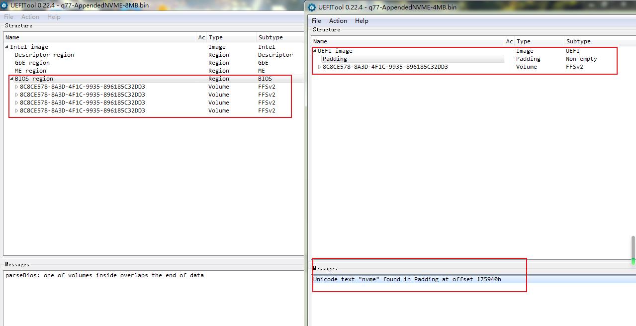
It would prompt error when opening 8MB bios with UEFITOOL,however you could mod it but you couldn’t find any DXE driver in all of the GUID: 8C8CE578-8A3D-4F1C-9935-896185C32DD3
4MB bios didn’t prompt error,but you you couldn’t find any DXE driver in all of the GUID: 8C8CE578-8A3D-4F1C-9935-896185C32DD3 too!
I tried to dumped the bios region by FPT(just name it fptbios),What the hell!one of the GUID: 8C8CE578-8A3D-4F1C-9935-896185C32DD3 show all DXE driver!!!
I compared the fptbios and 8MB+4MB bios,I think the DXE driver exsist in the PADDING region of 4MB bios,but I don’t know how to mod it.
Btw,I post months ago that modded bios of LENOVO Q77(is7xm),someone modded the PADDING region too.
About Lenovo B75 modding & flashing
Did you know something about the modding of the PADDING region?Thanks~
@gloobox - Without looking yet, normally I would compile those two BIOS, then work on modifications.
Also, without looking yet, I don’t know what you are referring to about GUID 8A3D-4F1C-9935-896185C32DD3 - not all BIOS will have text names or descriptions for all modules, some have none on all modules and this is normal.
OK, I checked, and still don’t know what you mean or why you are referring to that GUID 8C8CE578-8A3D-4F1C-9935-896185C32DD3, this is simply the main volume GUIDs (Same GUID is used for all volumes)
I will check the other thread about the B75/Padding, yes, I probably know about modding that file padding too.
Often, padding only contains info (like serial or other), but sometimes can be FIT table or microcode and sometimes some random module too just depends on BIOS type and engineer, and some BIOS tools may show area as padding while others do not.
I’ll have to check it out for you and let you know.
So many BIOS you upload in other threads, like above BIOS is Q77 something, I assume Q77 board, correct?
When you do this on unrelated threads, for my sanity, please always mention exact full motherboard name at link of BIOS, so I can keep in proper folder on my end, thanks!
Also, do you resell or repair boards? Only curious because you seem to be like me, always have a different board in your hand 
Here is Q77 a/b appended and modified, also re-split (8MB first when compiled, if you go to do compile yourself)
NVME goes into 5th volume in BIOS region, 3rd after first two NVRAM volumes.
http://s000.tinyupload.com/index.php?fil…392699675460021
@Lost_N_BIOS
Many thanks!
Forgive my poor english.
Let me show some pic and explain my post above.
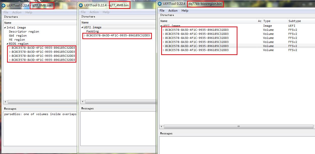
I dumped the q77_8MB.bin and q77_4MB.bin bios file by the SPI programmer,and dumped the biosregion.bin by the FPT.There are totally 5 "GUID 8A3D-4F1C-9935-896185C32DD3"s in the q77_8MB.bin and q77_4MB.bin. But there are 6"GUID 8A3D-4F1C-9935-896185C32DD3"s in the biosregion.bin.
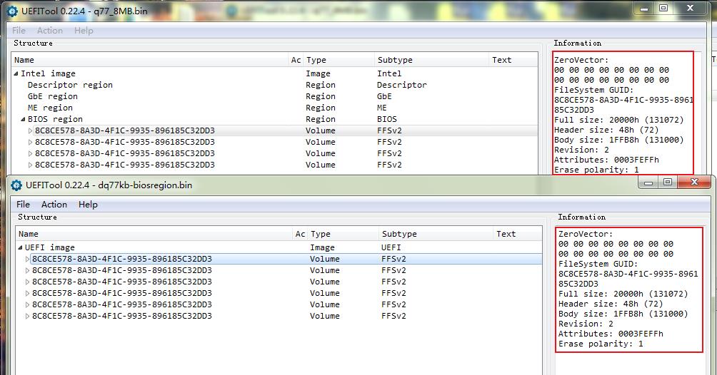
After comparing with them.I found 5 "GUID 8A3D-4F1C-9935-896185C32DD3"s in the q77_8MB.bin and q77_4MB.bin were the same as biosregion.bin(ZeroVector,Full size,Header size,Body size,Revision,Erase polarity are the same). And what’s more,There is no any DXE driver in these 5 "GUID 8A3D-4F1C-9935-896185C32DD3"s.
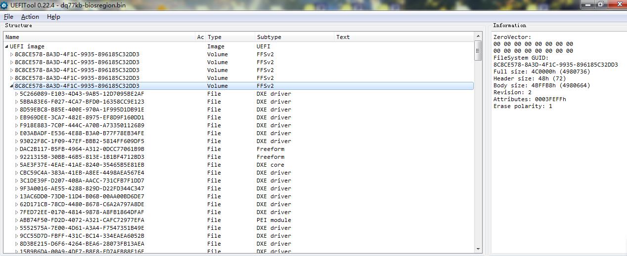
I found ALL DXE drivers are in the the excess "GUID 8A3D-4F1C-9935-896185C32DD3" in the biosregion.bin.
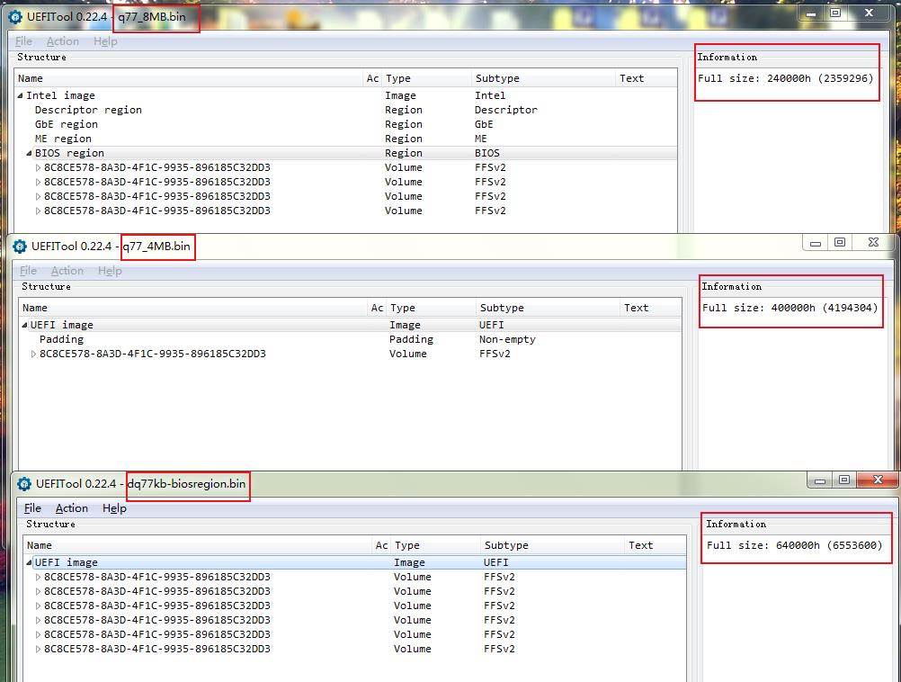
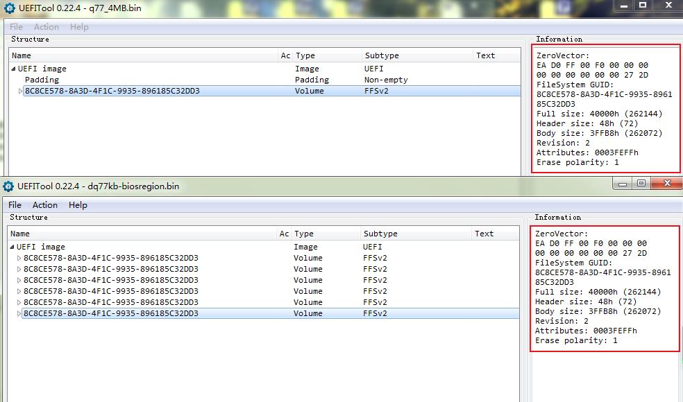
And I wonder where the data of biosregion.bin’s excess “GUID 8A3D-4F1C-9935-896185C32DD3” is in the q77_8MB.bin and q77_4MB.bin.After I compare with them again and again,I found the bios region size of q77_8MB.bin and q77_4MB.bin was the same as biosregion.bin.
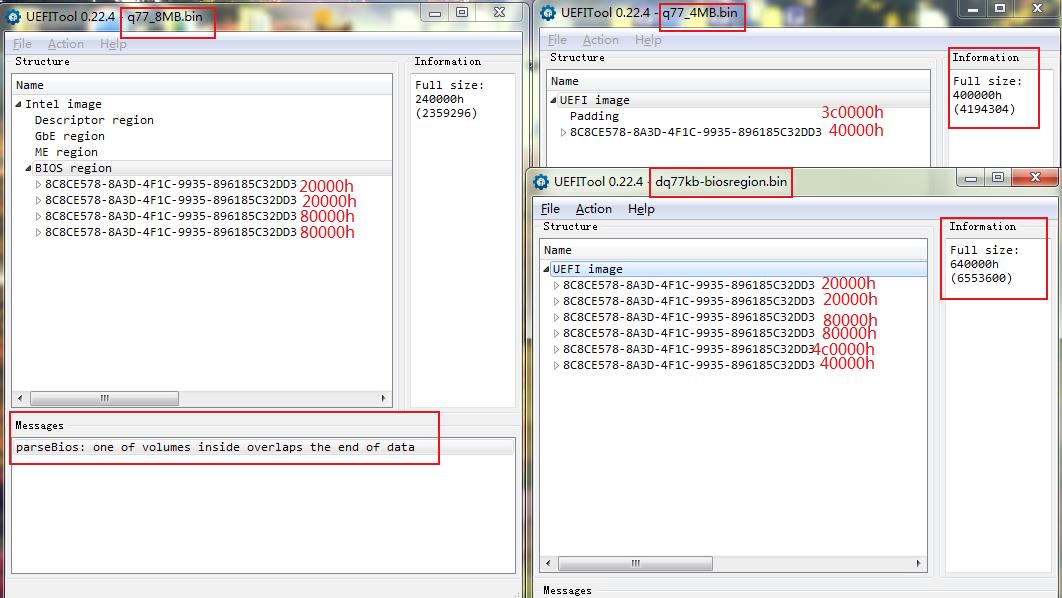
I thought at first the Padding in the q77_4MB.bin was the same as the excess “GUID 8A3D-4F1C-9935-896185C32DD3” in the biosregion.bin. But now I see the size are different between them,and they are 100000h apart(hex).
And I found the total size of 4 "GUID 8A3D-4F1C-9935-896185C32DD3"s in the q77_8MB.bin was 140000h and less than the the full size(240000h),and they are 100000h apart too.I also see the Message under the window:one of volumes inside overlaps the end of data.
So I think the data of biosregion.bin’s excess “GUID 8A3D-4F1C-9935-896185C32DD3” is exist in 100000h date hiding in the q77_8MB.bin and Padding in the q77_4MB.bin.
And months ago I found someone could mod the LENOVO IS7XM mobo which has two bios chips (8MB+2MB).You are right,IS7XM’s SB is Q77 or Q75 or C216,I was told B75 mistakenly and I would correct the post.
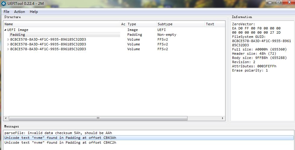
Actually I received the 8MB+2MB modded bios files,but it was OK just flashing the 2MB bios.I parse the 2MB file with UEFITOOL,and I found NVME unicode text was found in the Padding part.
So I think only adding the NVME module into the 2MB bios,the mobo can be modded successfully.
OK,now would you understand what I said above?
And Could you tell me how to add the NVME module to the bios of DQ77KB?
I think a interesting method.
Would it be OK that I combine 8MB bios with 4MB bios into one file(12MB),and mod it,and then split it into 8MB bios and 4MB bios?
Oh,I am just loving the bios modding especially NVME and I am an amateur to make it.(I think you are a technical engineer )When I am free,I would bought some second-hand(SPECIAL PRICE!) mobos I never modded and mod the bios,and sold them after modding it successfully.And sometimes I borrowed some mobos from my friends.Just for fun.
@gloobox - Yes, that GUID is all “BIOS volumes” The difference you see is because of where the BIOS is split in two. Sorry I didn’t explain that better when I was explaining where it’s split!
NVME Mod I did is not in padding file, it’s in the main BIOS region. I suggest you reprogram both chips with the BIOS I sent you, they do not match at the split (different data is there), if you don’t use the 8MB I sent too.
On DQ77KB, I don’t know, if this board has two BIOS chips then yes, dump them, join the files, then mod, then split back and program back in.
I buy and sell a lot of boards too, well sometimes I do, but not lately as PP is a pain in my rear now 
Thank you for report back on BIOS, I assume it would be OK. Please program both files I sent you, otherwise BIOS could corrupt or brick later if you only program in one half of what I sent you.
@Lost_N_BIOS
Actually I just flashed the 4MB bios file,and it runs well all the time.when I opened the 4MB bios file with UEFITOOL,I could find the Unicode text “nvme” in it. (8MB bios file didn’t have Unicode text “nvme”)
So I assume that the nvme module exist in the Padding of 4MB bios file after you splited back the whole bios file.
Btw,what does the “PP” mean?
Yes, I understood you did that, But I am saying don’t do that, the data does not match when you split volume like that. For your sanity, in case random issue happen later and you can’t find out why, flash both files so BIOS is proper and complete.
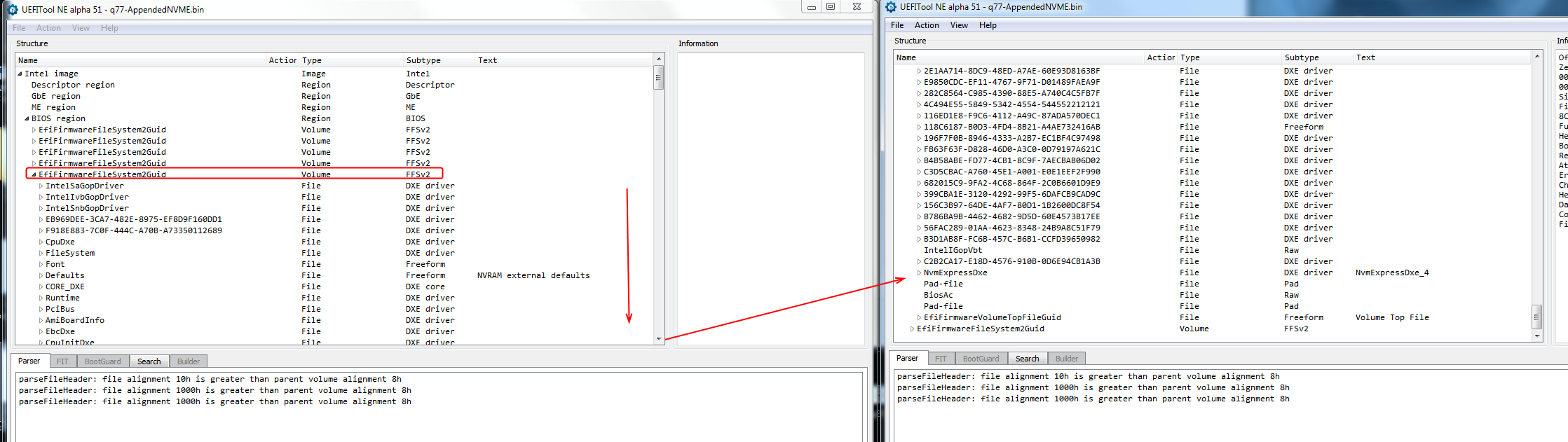
NVME is not in padding, it’s in main BIOS volume (Where you find setup and AMITSE etc). Look at the complete 12MB image in UEFITool, then you will find NVME mod inserted at 5th volume in BIOS region, 3rd after first two NVRAM volumes.
Here, I show you in image of UEFITool
PP = Paypal
I know the NVME module exist in the 5th volume in BIOS region.But you can’t find the 5th volume in BIOS region in 8MB bios file or 4MB bios file.
As I said above “So I think the data of biosregion.bin’s excess “GUID 8A3D-4F1C-9935-896185C32DD3” is exist in 100000h date hiding in the q77_8MB.bin and Padding in the q77_4MB.bin.” (The excess “GUID 8A3D-4F1C-9935-896185C32DD3” that is the 5th volume in BIOS region you mention)
After spliting the complete 12MB image,the pic above show the NVME module was located in Padding of 4MB bios file.
That’s because you can’t properly open the files in UEFITool unless the image is compiled, this is a split image, same as why you can’t open both files in UEFITool (8MB will tell you file is truncated).
There is no padding, I showed you in image exactly where and in what volume (not padding) the NVME Mod is inserted, there’s no other way to explain this.
This BIOS is split at an odd place, in the middle of BIOS volumes and directly in the middle of live data, and this is why I said it’s best for you to program in both files I sent.
No padding in 4MB BIOS, what you see like that as padding is an actual BIOS volume (Split in two, so you see half there, broken volume, appears as padding etc), but the tool is just seeing at it improperly (Because that “Volume” Not padding, is split in the middle, so UEFITool thinks it’s a padding or broken volume, similar to non-UEFI-Data)
It only looks that way because the volume isn’t parsed properly because it’s split in the middle and you only have half the volume in that 4MB file. And because correct way is to not open this file, as it’s a partial image, split right in the middle of data
This should be huge sign to your eyes, confirming on why it’s VERY important that you program in both files I sent you. Otherwise you have half of the volume from old/original and half from what I edited, and the data does not match in each file at this split location
I’m really surprised it boot and surely something is going to corrupt eventually if you don’t write it in there properly.
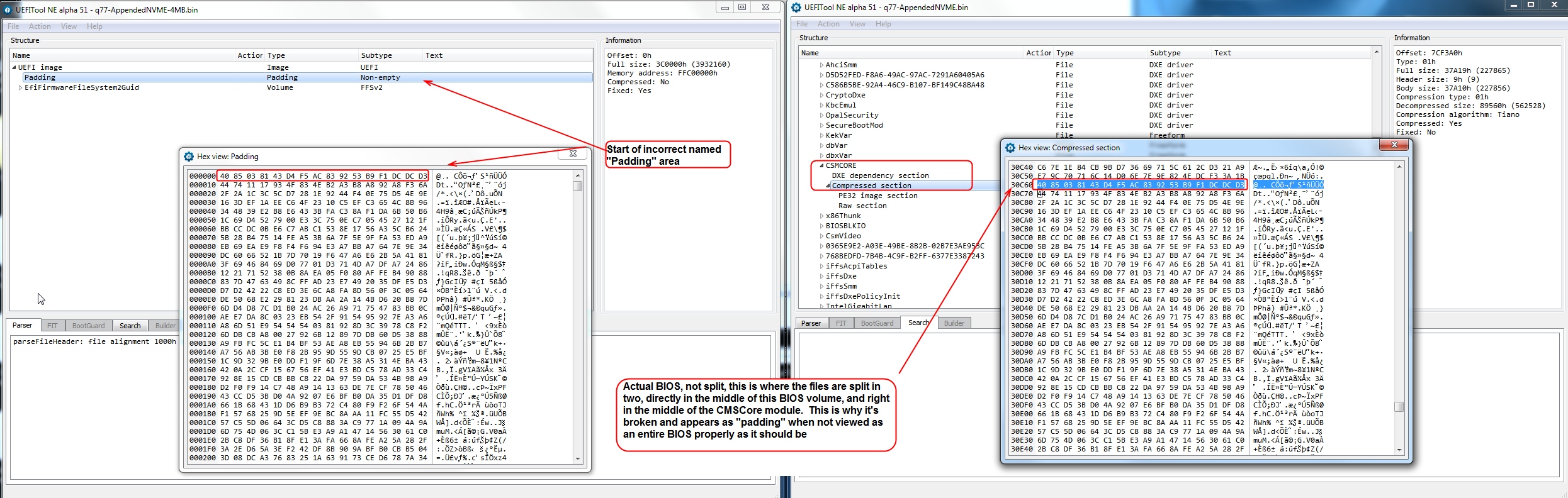
* edit - Here @gloobox - I show you better way, I hope  This BIOS is split right in the middle of compressed CMSCore file, very important you flash both.
Here, now you can see the split directly at your “padding” or in the exact location in the middle of the BIOS volume, and right in the middle of the CMSCore module
This volume is “broken” when viewed as a 4MB file due to this split mid-volume, that’s why it looks like that If opened this way (not proper way to view or edit this BIOS, or any split BIOS, but especially this way due to the split location)
@Lost_N_BIOS
Actually I didn’t know what “padding” mean.But I just think that NVME module exist in the part of “padding” which was showed in UEFITOOL.
Haha,thanks for your explaining and I finally konw what padding really mean.
But the way,what way did you mod NVME module? UEFITOOL or MMTOOL?
I found that it wouldn’t change the file header code of ASUS CAP file with UEFITOOL,but it’s would change with MMTOOL.(So we could just add the NVME module to the M5A97 R2.0 with UEFITOOL,and usbflashback it!)
I’m glad you see now, hopefully you do anyway! Yes, this is not normal padding, like you see in other BIOS, or even in this BIOS in other places maybe, this Padding you are talking about is only due to BIOS cut in half and then opened wrong by UEFITool due to split.
I did NVME mod with UEFITool 25, this is what I always use unless there is an issue and I’m forced to use MMTool (VERY RARE, really do not like using that tool, luckily it’s rare occasion where I have to)
For Capsule BIOS, I always extract body of those BIOS, edit, then manually put back inside capsule with hex editor = signed BIOS always and USB Flashback no problem, this is my standard procedure for any Asus BIOS (Which this is not Asus, so not sure how we’re talking Asus now  )
)