Hello everyone,
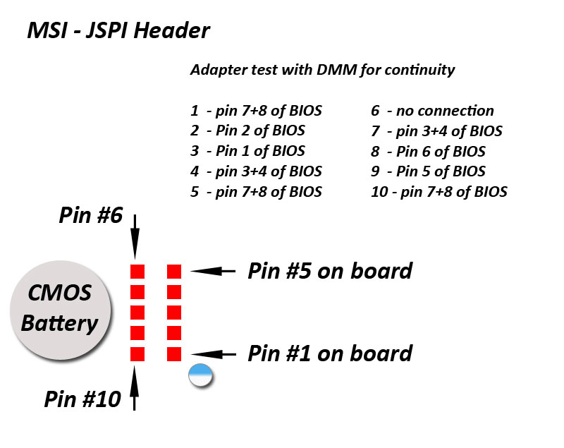
I have a bricked Mainboard due to a bad Bios Update. The Update erased the chip and then the PC shut off completely without flashing anything.
The board can be turned on (LEDs lighting up etc.) but obviously it does not display anything on screen or boot up. I guess that’s what happens when the BIOS chip is empty?
I have tried using the JSPI1 pins of the mainboard in combination with the CH341A but have not succeeded. The connections should be correct according to pinouts I’ve found via Google. The chip can not be detected, reading goes to 100% and shows empty, writing give a time out.
So I am now trying to flash a bios file onto the chip using my CH341A Programmer and a SOIC test clip. The clip is aligned correctly (I’ve tested that every pin of the chip is connected to the correct pins on the CH341A and that there are no non-connected pins etc.). So from what I see, everything looks fine. Still the CH341A Programmer software can not detect the chip (I’ve tried version 1.13, 1.18, 1.30). 1.13 and 1.18 seem to read the chip but 1.30 only says that it can not detect the chip.
I have totally stripped the mainboard from all components (cpu, ram, etc.).
I tried with cmos battery in and out, with power to the mainboard conntected (not turned on and turned on). Everything leads to the same result. I’ve tried so many things already, it really drives me insane…
I’ve also checked the chip specifications and it says “WP#ACC” on pin 3. Here is the description from the specification:
WP#ACC:
Write protect: connect to GND;
9.5~10.5V for program/erase
acceleration: connect to 9.5~10.5V
Could that be a problem since I can not see anything like 10V or similar on the CH341A programmer (even tho I can select the chip model manually, so it should be supported)?
Or does anyone have an idea what the problem could be here?
Any help is appreciated as it might keep me from going insane ![]()
Also: I can’t desolder the chip since it is in a bad spot with small resistors and plastic around it and I’m totally not equipped for such a precision soldering. So I have to work with either the JSPI1 pins or the test clip.
I’ve used CH341A successfully with 1.18v software and even with ASProgrammer 1.4.0 (did you try it ?).
Anyway if your SOIC clamp is correctly inserted both on pin chip as well as on CH341A, using proper drivers/software
you must be able to read eeprom (if it can be readable).
Did you also consider that your eeprom could be simply “fried” and unable to be read ?
If the chip is still soldered to the board it could be a problem with the power supply. Please take a look at this thread beginning at post #4. In worst case you need to desolder the chip or lift some legs.
[Guide] Using CH341A-based programmer to flash SPI EEPROM
BTW, connecting 9.5-10.5V to WP#/ACC is just for program/erase acceleration, not needed for normal flashing. But if WP# is connected to ground chip is write protected.
Oooh, be very careful when lifting pins… They can easily break!!!
The mainboard was running fine until the owner used afuwin to read the bios into a file, inserted a new microcode for his cpu with mmtool and tried to flash the resulting bios file back.
afuwin erased the chip then the app crashed while trying to write it. The pc froze and was shut down.
I think the chip should be fine, since it’s unlikely that it was damaged by afuwin. Or isn’t it?
Also I can read/write other chips (like Winbond W25Q64BV) if I put them in a SOIC socket.
When I use the test clip on the bricked chip (haven’t used it much tbh), it says “Connected” in the software but it detects the chip as “Unknown” from “Other” manufacturer.
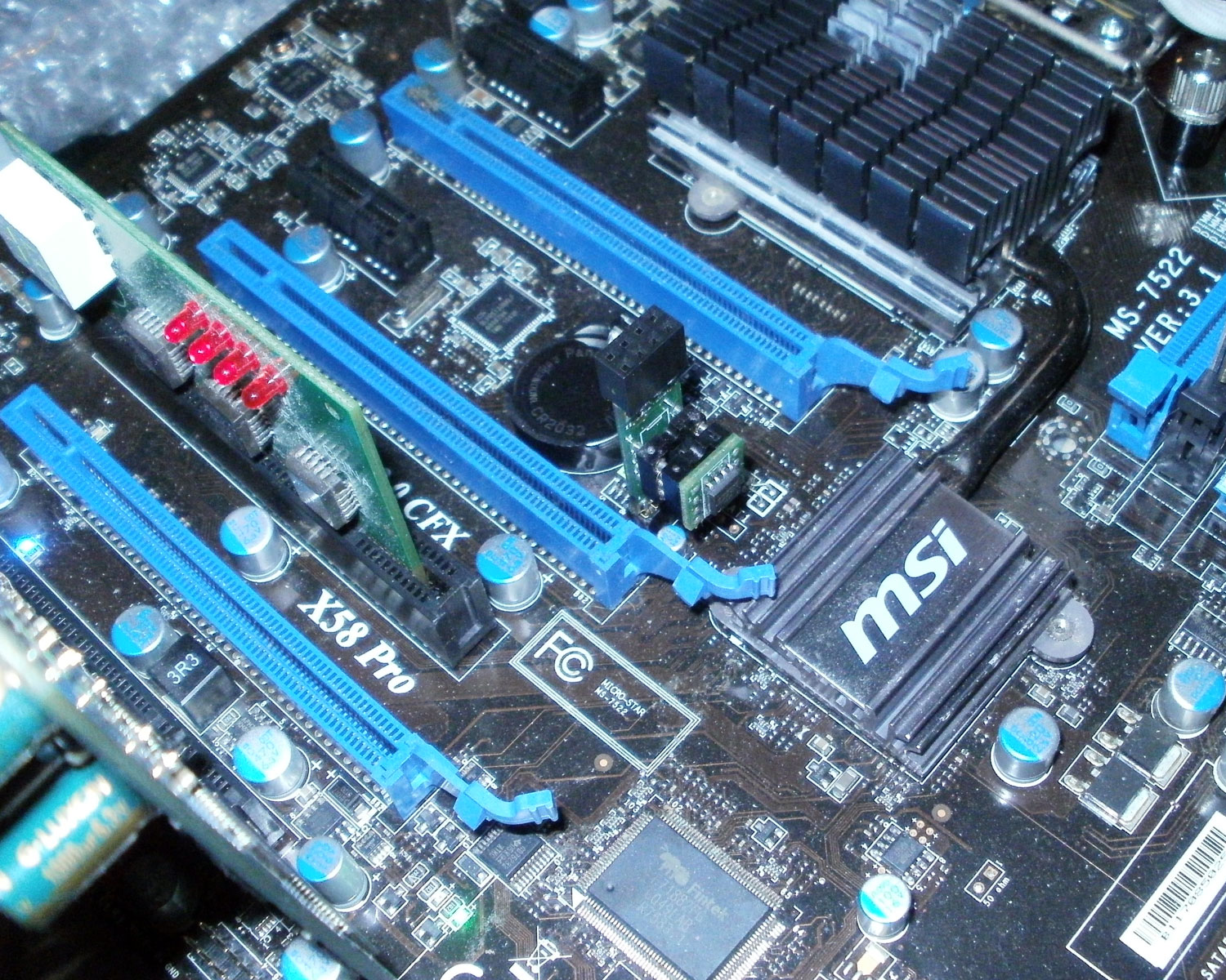
Is it possible that the circuits on the board somehow make it fail? The board is a MSI X58 Pro-E (MS-7522).
I’ve also build a custom cable for the JSPI pins and connected them to the CH341A like this:
Where left side is the slots of the CH341A (same pin numeration as the chip itself from 1-8) and on the right side I was measuring which pin of the JSPI1 connector is connected to which pin of the bios chip.
Accordingly I made a cable which connected the pins with the same number together.
Unfortunately it didn’t work either. Could it be that the board itself is causing problems or something like draining voltages etc? Or that the CH341A programmer does not get enough power for the whole board (if it is connected all together) since I’m using it on a notebook usb port?
Also as a side note: It is possible to send the bricked board to MSI and use their BIOS Update Service, so they will reflash the chip with a working bios. I wonder how they do it, since somehow I doubt that they desolder the chip and resolder it after flashing/replacing. I think they would just connect something to the JSPI1 pins and flash right away?
So basically he could just send it in to MSI, pay some money and get it back with a working BIOS. The problem is, they only flash their official BIOS files. So if he wants to get a microcode update, he would have to flash the modified BIOS again. Probably with afudos or something then, instead of afuwin. But still, if something goes wrong again, it’s bricked again.
So I prefer to find a way to being able to recover it myself if it happens again.
Yes, they would use the JSP1 pins but not how you were thinking. When using that, did you switch the programmer to serial mode instead of flash, and do you have the serial driver installed? Which type of programmer are you using?
Try 1.31, included in package below, maybe it will work better?
https://www.sendspace.com/file/gtcmvd
Serial driver here
http://www.wch.cn/downloads/CH341SER_ZIP.html
The JSP1 is for booting from another BIOS source, not reprogramming. This works like you’d imagine, I use it with a PCB style jumper board with spare rom on it and MSI on one end, Asus connector on the other.
My adapter looks like this
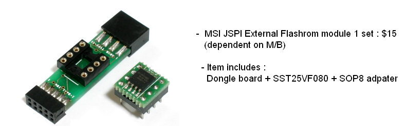
You could wire up your programmer in serial mode, with BIOS loaded into memory/buffer (ie read the BIOS file before doing anything), then boot the board. But I am not sure if it would hold/send the source like an actual flash rom on adapater
That is how the above adapter works sort of, I load a BIOS onto the spare rom, connect it to the JSP1 header and boot to that BIOS on the chip, then go to DOS, remove the jumper fixture and reprogram the main BIOS.
On my adapter, it looks like only pins 1-4 + 6-9 are used = (5 & 10 unused, two on same end)
I’m sure MSI would probably RMA that for you, if within warranty, tell them bad BIOS flash and they’ll fix it right up.
Get a better created BIOS mod next time around and this wont be an issue. If you want, upload the file that killed the board and I can check it and see if there is a reason why it was a bad BIOS mod or not.
If you do that, include a copy of the original version too, thanks!
Yes, I actually used the JSPI1 pins with the CH341A in programmer mode, since I measured with a multimeter that the pins are directly connected to the pins on the bios chip (except for WP (pin 3)).
So I thought it should work just like using a test clip to program the bios chip itself (which also failed).
Where do I get this MSI JSPI External Flashrom module (I live in Germany)? Does it fit on the JSPI1 connector or is JSPI the same as JSPI1?
What about the BIOS chip that is already on the board? Since the pins are connected, wouldn’t the two bios chips interfere with eachother?
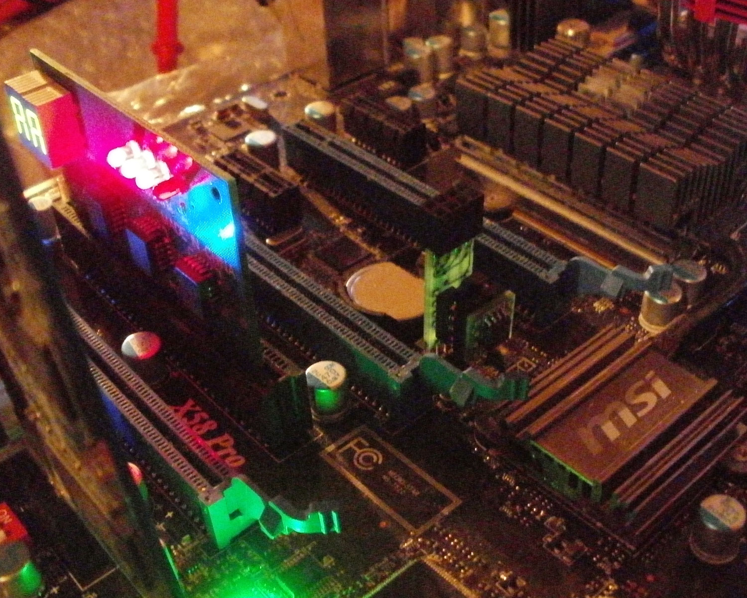
I just tried to build one myself like this:
I used the JSPI1 cable together with a SOIC socket in which I put in a BIOS chip that has the correct bios flashed on, but it did not boot up. The board still powers on like before but stays dead (no beeps, etc.)
Unfortunately I did not have the same 4MB BIOS chip (MX25L3205DM2I-12G), so I tried a Winbond W25Q64BV chips (8MB). Not sure, if they are just incompatible or the whole process does not work (cable too long ,etc).
Should the 8MB chip work, if I write the 4MB rom onto it (ignoring the last empty 4MB)? Or do I have to get exactly the same chip (which would take weeks, since I couldnt find them on ebay, so I’d probably have to order them from china)?
Regarding your pcb flashrom module: Can you tell me which pins of the JSPI socket are connected to which pins on the bios chip, to make sure I had the correct pins connected?
If I could, I’d try desoldering the chip and program it directly with the CH341A, but the spot is kinda tight and I don’t have such a small soldering iron / station. So I’m a bit scared about damaging the plastic stuff around the chip or destroying these tiny little chips next to it (not sure if they are resistors or anything else, but if I accidently remove them, I’d never get them back on  ). I’d have to hold the soldering iron nearly in 90° to the board to get to the bottom pins without touching the plastic:
Also I’d prefer a better solution, in case the bios get’s messed up again in a future flashing.
What I don’t understand is: If you send the board to MSI, they charge you 25€ for the reflashing including shipping. The board has to be clean (removed all other components, like cpu, ram, etc.). If they would use the JSPI1 interface to sideload a bios, they would have to insert a cpu, ram, connect a display, etc. and then flash a bios to the normal ship after remove the JSPI1 connection. Sounds for me like it would be too much work for such a price. So I assume they just connect something to that JSPI1 port and flash away!?
It’s driving me insane…
Yes, do not solder any of this since you are not setup to do so and are not familiar with this type of soldering, it’s not easy with lead free solder and resistors and plastic that close to what you are working with
When anything is connected to the JSPI1 pins on the board, the main BIOS is bypassed. This is why I said, boot to DOS with BIOS on JSPI, remove that cable or BIOS, and flash the main BIOS once in DOS since it’s then enabled again but not in-use.
JSPI1/JSP1 same, just numbered on the board. Yes the device I showed fits, it’s designed for this use and I have used it may times.
You can get from this ebay seller, message him and tell him you want that JSP1 module only, and a 4MB/32MBit BIOS chip instead of the default 8MB/64MBit one, he will hook it all up and he ships quick so you should get in 10-15 days usually.
https://www.ebay.com/itm/280668537456
I’ve purchased from him many times, always friendly and always quick shipment (It comes from Korea) - message him and tell him you want the following
MSI JSPI External Flashrom module 1 set : $15
- Item includes : Dongle board + SST25VF080 (Change this to any 4MB BIOS, ask him what he has or show him list below) + SOP8 adapter
You would (usually) need 4MB BIOS chip, at minimal, due to how they are designed (8MB usually quad flag operation and 4MB not always, sometimes dual and sometimes quad if dual BIOS). Does not have to be the same chip, but you want same voltages
However, I just tested very similar chip you did and it works on JSPI Header! I tested with MX25L32 and W25Q64FVSIG, both worked fine in this instance (erase full chip before write for the 8MB just in case). I used BIOS 8E0 stock as-is
I set it up for you with the adapter installed and booted to BIOS to see which direction it goes for when you purchase one, it always confuses me and you can tell by instant HOT BIOS chip 
Here is pinout as I tested, hopefully this will get it sorted out for you. I am confused as you will be at the dual pins instances, I don’t know how/why, I’d have to ask the seller about that one (And I will ask right now, Q sent to seller, will let you know his reply).
Here’s some brands, and search terms to aid in your BIOS flash rom hunt, if you don’t end up purchasing a JSP1 adapter from ebay link
W25Q32 (example W25Q32FVSSIG)
winbond
SST 25VF032A
MXIC - Probably your exact chip here, or close enough match - https://www.ebay.com/itm/263855987134
MX 25L32 / MX25L32
32Mbit = 4MByte / 4MB
Depending on how you want to use the chip, SOIC or SOIC-8/SOIC8 is soldered on type, DIP8 is Asus/Asrock type which you could also use depending on your adapter setup
I have successfully recovered the board now with a homemade adapter like the one Lost_N_BIOS posted above.
I used the same 4MB chip as the one that is soldered onboard.
The board booted from the recovery chip and I was able to reflash the onboard chip with AFUDOS afterwards with “afudos bios.bin /p /b /n /c”:
I’m not sure if I should have done also /E and /K!?
/E - Program embedded controller block
/K - Programm all non-critical blocks and ROM Holes1
There is still one problem left now:
The onboard LAN controller did no longer work in Windows. Device manager said, the device could not be started.
So I removed it from device manager (with option to uninstall driver aswell) and let it search for new hardware.
It then reinstalled the Realtek LAN adapter and it was shown in the available network adapters in Windows.
So after configuring IP, etc. it worked fine.
But as soon as the power is completely cut off (power cable pulled out, of course after System shutdown) the same problem appears after the next start. I need to remove the device again and let Windows reinstall it afterwards etc…
So maybe there is something still messed up in BIOS or Windows has now something messed up with the new BIOS version… will have to evaluate this a bit further.
Here is the adapter I built, in case anyone wants/needs to build one themselves:

I used a dremel to cut off the 20pin USB3.0 connector to the required size (not all holes are connected, so they needed to be meassured with a multimeter before cutting to get a working connector).
Then I cut the cable about 5cm above the connector and soldered the single lines inside to 2.54 female connectors.
Afterwards I simply connected them to the SOP8 socket and placed a programmed chip into it.
Here is what it looks like:

Maybe it’s not very pretty, but it’s easy customizable and gets the job done.
Awesome you were able to finally get it updated!
Yes, I always use /p /b /n /k
/e I never use, but you can it will be OK
LAN issue is due to stock BIOS does not contain LAM MAC ID, So your LAN MAC IP is now 88:88:88:88:87:88 correct, or similar?
Do you have a backup dump of your BIOS before all this happened? Dump from anytime will work for this. I can get LAN MAC ID from it and insert in new BIOS for you to reflash. If you do not have this, LAN MAC ID is on a sticker on my board, right above the LAN ports.
Send me a current working dump of your BIOS with the programmer with SOIC8 jumper cable. This is not required, but it’s easier for me to update that way.
Same applies for your board UUID, serial number, Windows SLIC activation etc all that will be contained in a previous dump if you have one, if not it’s all lost now except what you can find on the board stickers.
Thanks for posting your guide/method for making adapter so others might use in the future.
So, what was the problem intially, with the adapter and all that I mean?
Sadly I don’t have the original backup anymore (seems like the file is gone somehow).
The MAC address matches the address on the sticker on the LAN port, I’ve already checked that.
I have already tried different Realtek drivers and a winsock reset, which didn’t fix the problem.
It seems to be caused by the hardware / bios itself, since it only gets triggered when the power supply is turned off or the power cable gets pulled out, not on normal shutdown / reboot.
So as long as there is power connected to the board, everything is fine. The CMOS battery is completely new and provides 3.3V, BIOS settings are saved throughout powerloss aswell.
After power loss the device shows “This device cannot start. (Code 10)”. A full uninstall of the device and new install gets it working again.
Just reflashed with “/P /B /N /K /C”, didn’t fix the problem.
Yes, I never meant any of those would fix the issue, I only said you can if you want
To fix the issue it’s a BIOS thing, as mentioned please send me a current working dump of your BIOS with the programmer with SOIC8 jumper cable.
Also, without anything fixed on your end, reboot if you have to, run ipconfig and tell me the current invalid MAC Address. And also give me the actual correct MAC address from the sticker on LAN port
All problems solved, so for completeness (in case anyone else has a similar problem):
Turns out, the MAC address was messed up ("FF FF FF FF FF FF") when the BIOS flash went wrong or during the recovery process, causing the LAN adapter to not work until it gets assigned a correct MAC address.
Interestingly Windows automatically set the correct MAC address when I removed the adapter via device manager and installed it again. This was actually a bit confusing while trying to pinpoint the problem, but I guess it must have something to do with the fact that Windows already knew the correct value before the BIOS flash went wrong, therefor being able to asign the correct MAC address again.
To fix the MAC address permanently, I used the EEPROM/EFUSE Programming Utility for Realtek RTL8168 Family Ethernet Controller (PG8168.EXE).
PG8168.exe /efuse /barmac
After that I simply entered the desired MAC address and it was flashed successfully.
Now the MAC address is correct and also survives a power loss.
Note: The mentioned tool (PG8168.EXE) works for the Realtek 8168 family only, so if you have another LAN adapter, you need to get the appropriate programming software for this specific model.
how to prepare spare bios ic to load from, jsp1 ?
Hello everyone
Thank you for the very useful information.
I have exactly the same problem with the motherboard MSI 7522 Pro-E Rev 3.1.
I bought an MX25L3205D chip (I don’t know for sure if the same one is installed on the board or not)
Assembled the same cable using SOP8 socket.
The pins of the JSPI1 connector 7,8,9 were closed between themselves and connected to the 3,4 leg of the bios chip. The board started successfully, I pulled out the chip, I’m trying to flash the bios of the chip on the motherboard, but the process of erasing the chip freezes at 0%. If you click on Reset, the process goes up to 11% and restarts.
Please tell me where the error may be.
2018…try to address to other users if active (helly100), except Lost that is no longer active on the forum.
Not sure what exactly you were doing, but use the adapter to boot your PC from an USB stick into DOS (I think I was using FREEDOS from Ultimate Boot CD or something). When you are at the DOS command prompt, unplug the adapter from the JSPI pins and then use afudos.exe to flash the chip.
Don’t use the BIOS itself to flash the chip! I’m not sure which version of afudos I was using, but I think it was version 4.xx (possibly 4.40?) You can download multiple version onto your usb stick and try them out. If something goes wrong, you can always reboot with the adapter and try again. Use the command mentioned above:
afudos bios.bin /p /b /n /c
(assuming “bios.bin” is the filename of your bios file)