@Lost_N_BIOS
Question see more further below:
–
Background:
I’ve got an “MSI ZH77A-43” (Ivy Bridge) Mainboard, bought used from ebay, which didn’t work any reliable at first.
(most probably memory compatibility issues with BIOS 1.4, it got shipped with)
But I could repair it, by a firmware-update flashing the latest (stock) MSI BIOS 0x1.A (1.11) via a “TL866II Plus” external programmer via in-in-ciruit.
Download=>
https://download.msi.com/bos_exe/mb/7758v1A.zip
Flashed this (extracted) => E7758IMS.1A0
Before, I tried to dump its original firmware with “FPT”, and updating it via M-Flash.
As the board suddenly no longer booted (a bit later), “FPT”-dump-method, etc. wasn’t possible.
So I had to use my programmer to dump the firmware, (via ICSP)
(- Desoldering EEPROM was out-of-option for me,
which I had tried before (with hot-air-gun) on other product, (which seriosuly had damaged other board <==next to EEPROM a few thin through-connections copper-wires thorugh small holes cracked/melt/slipped off) )
To avoid such situation, that this could happen here, too,
I did best for the situation I could think of, and backuping original-firmware with programmer via ICSP.
As the programmer didn’t get the Chip-ID, without powering the mainboard, I had to power the board, and with some kind of ATX24pin-Green-Black-wire-shorting-trick on the PSU, and RST-Pins, later PWR jumpering etc.
With this trick, programmer got Chip-ID permanently, and reading firmware appeared to work fine, and
Still after several re-read-attempts, I got always two alternating+repeating checksum periods, with only 1 byte in difference, where within it always gets checksum 1, and at next 3-min-cycle checksum 2,
so result only those two cycle-checksum1_(only)-and-checksum-2(only)re-reading-oot periods, and so forth
(ME Analyzer shows ME firmware on both 2 different checksum-dumps and CPU microcode) - So both dumps should be OK.
–
Trying an other external programmer was no option for me, as most probably too much Vcc-power draw from programmer, without powering mainboard, so another model of ext. programmer would have most probably same issue without powering board, too, like my “TL866II Plus” external programmer.
—
So this is the best, I’d have, two different “MSI ZH77A-43” original v1.4-firmware-dumps, but with only 1 Byte in difference, and a working ZH77A-G43 mainboard
after flashed stock “MSI ZH77a-G43 0x1.A (1.11)” -also via ICSP with the programmer, which got a least here always 100% identical result - (also) by necessray powering-the-board-trick, by the the Green-Black-wire-PSU trick on the PSU, and RST-Pins/ (later) PWR jumpering etc. (which recommended on flashrom-site)
–
I’d like to restore original serial-number, which came from 1.4 firmware, as it’s probably lost from flashing over the latest (“stock”) BIOS".
Still I’m not certain if the original firmware really had had a serial number.
(I couldn’t check with e.g. “dmidecode” in Linux nor with “CPU-Z”), as the board hadn’t booted and doesn’t start with the original 1.4 firmware (memory issues)
Would there be a way to find it out, if there a serial number existed, and if yes, how to restore it into the newest (bug-fixed 0x1.A BIOS)?
See attachement below of original 1.4-firmware dumped,
as comparison stock 1.4 firmware https://download.msi.com/bos_exe/mb/7758v14.zip
and link further above to newest stock 0x1.A firmware
Thanks you, for already paid attention, and for helping so many people, and I’d love to donate s.th. a bit. 
I’m familar with Fernando’s super guide, so you don’t need to tell me how to add nVME module, CPU-microcode, because the board still booted fine with the modified stock 1.A BIOS, and Fernando verified it, so don’t worry
(I’m not expereinced how to add microcode, for non-existent-microcode-cpuid/pt, with only few free space after microcode-section - but I’d don’t need to do that on this board)
EDIT by Fernando: Thread title shortened
@Vincent12 - Sounds like incorrect FPT flash caused brick (it happens, wrong parameter used, wrong file given for parameter used etc)
Some boards do not put serial or UUID in BIOS, sometimes LAN MAC ID not there too. I cannot remember if MSI does or does not, nor how consistent they are about this.
Please give me your original BIOS dump from this board, before you bricked it via FPT (I assume you made a FPT backup first, that will be fine)
I can add in any microcodes you want, just let me know what CPUID you need added 
YOu have two attached files above, I assume these are programmer dumps, made AFTER you bricked the system, correct? If yes, I don’t need those at all. OR, is one of those a dump from a totally different board of the exact same model, that was never bricked?
If both of those dumps are made from ANY board, after you programmed in BIOS with hardware programmer, then no one needs any of those (even you). A dump of a BIOS after you program in stock BIOS with programmer means just what you’d expect, a copy of that stock BIOS without any board specific info in it
Sounds like the latter is the case here, and what you mean. Both files are dumps, after you programmed in some BIOS with programmer, correct? If yes, useless for this situation, I could just download BIOS from manufacturer and would have same file.
I only need a dump of any kind, that you made before your bricked the system. And then, I also need a zip of images of all stickers you can find on the board, check front and back, check side/back of LAN port, check side of 24 pin, check top/bottom sides of PCI/PCIE slots.
If this is laptop, give me images of any stickers you find on bottom of case, inside back of that case once removed, any you see on the board and be sure to look on/around the memory slots, and under the memory or any add-on cards too.
You’re welcome
(Editing this post)
[Edit] Shorted way too much of text.
I’d have to admit, I’m (quite sure, but not to 100%), I tried to update firmware via MFlash (during which system crashed - [Edit]
I remember MFlash crashed, and I remeber that wasn’t with first three dumping (before modifying) (100% sure), then after a reboot, while I either wanted to redump firmware, to see if checksum changes after reboot, or then Flashing firmware with MFlash (so in one of the two latter (=afterwards) the system crashed. (But here now the system no longer booted entirely even after trying it 20 times, also cold-start and CMOS-reset didn’t help, so I couldn’t use “FPT”. I tried to use also “FPT” (even though I didn’t reognize yet, that MFlash-Dump was not the whole firmware).
So I tried external programmer (at least I had a dump from MFlash - where I just later noticed that it was only 6144 KiBytes). Same on 2nd and 3rd attempts. SO appears some kind of firmware lock/and or in the MFlash utility not to dump entire firmware, only the most important parts.
So the ext. programmer’s dumps are most probably fraud, as you proposing.
I had forgotten. It’s already over 14 days ago, when I had started to use the ZH77A-G43 mainbaord, so I’m/was not entirely certain for every single task, that I had tried out. But the rest where I wrote 100% sure, you can rely on it’s correct, that I dumped firmware, without messing with EEPROM in any kind.
--------------
I’m 100% sure I didn’t use “FPT”, as far I can remember, I tried “FPT” in Freedos, to dump firmware, before any modifying, but afaik had locked “flash descriptor lock”, (but probably bad memory in my head)
I’m 100% sure the baord right at start with 1.4 firmware had boot problems with RAM-memory, so I didn’t get to use “FPT” to dump firmware right in time.
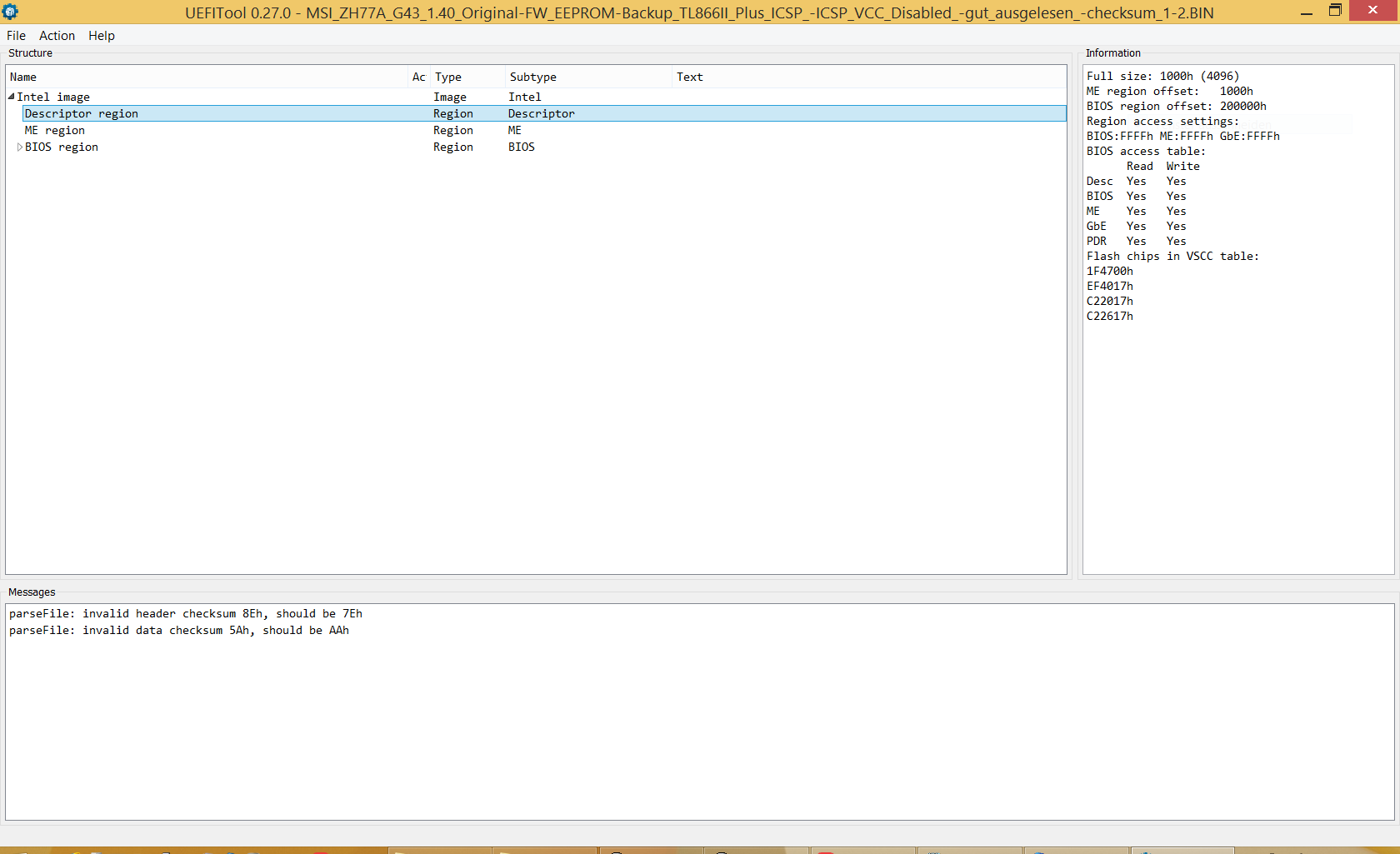
(I could have, as UEFI-Tool implies otherwise, (UN)locked flash-descriptor (read+write-access), of the possibly fraud ext.-programmer-dump, and same on 1.40 and 1.A stock firmwares).
[[File:UEFI-Tool_says_otherwise_on_ext_porgrammers_DUMPs,that_FD_was_not_blocked_(but_maybe_due_to_fraud_dump).PNG|none|auto]]
-------------
Yes, I’ve got also an “MFlash” firmware-utility Backup-dump, (see attachment below), (pick one of the three which has same checksum to another one of the three, see name!)
which I forgot to mention,
(but it’s only 6144 KiBytes big - I had noticed that too late that 2048 KiBytes missing from whole 8192KiBytes, before writing firmware image with ext. programmer),
It’s 100% certain I didn’t write anything with “FPT” (why should I do such nonsense?) before dumping firmware with MFlash, and it’s for sure I didn’t flash anything with programmer before reading out firmware with MFlash. And I’m 100% sure about that I did(n’t) update firmware with MFlash before dumping firmware with MFlash. (If I used MFlash updating firmware/messing with EEPROM, I’m 100% sure I did this after making backup dump before, using MFlash, and external programming also after update making backup-dump with MFlash.)
So I’d be certain, that two of the (3) M-Flash Backups (time difference one minute, see timestamps) should be OK:
MSI_ZH77A_G43_1.40_Original-FW_-EEPROM-Backup_1_MFlash.zip <=================should be valid,correct?
MSI_ZH77A_G43_1.40_Original-FW_-EEPROM-Backup_2_MFlash_(checksum_different).zip <====(invalid?)
MSI_ZH77A_G43_1.40_Original-FW_-EEPROM-Backup_3_MFlash_(checksum_identical_to_1).zip <=should be valid, same as 1
- Here also with MFlash, directly at the 2nd dump, the checksum doesn’t match to 1, but at 3rd dump it matched to 1st attempt.
(I had noticed a status-progress-bar delay at 2nd attempt, where checksum not matching to MFlash dump 1 and 3, that the MFLash dump-progress-bar hung for a few seconds at ca. 17% - 100% sure), while with matching Mflash-dump 1 and MFlash-dump-3 with identical checksums, on both, the Mflash progress status bar went fluently through (without any delaying - 100% sure)
All three MFlash dumps are (without rebooting) in between. And while having stayed in firmware-setup.
—
Is it possible to recover potentially lost serial from the MFlash dump?
Thx for any help Lost_N_BIOS.
I promise I’d donate s.th. a bit to you, in any case, whether you could help or couldn’t to restore a possibly lost serial number - (and/or possibly due to my too bad expressing)
In any case, it’s not dramatic, as the ZH77A-G43 mainboard is running fine with the stock flashed firmware.
That I get two alternating checksum-period dumps of programmer, where in several attempts within a cycle, where it reads always checksum 1, and within next period where programmer reads always hecksum2, but flashing works perfectly (identical to source file),
I think it doesn’t have anything to do with programmer, as you proposed it’s probably coming from enforcing to power the board (by green+black-PSU-wire shorted), while holding it PWR-button-pins shorted.
And PWR-button in hold should toggle the mainboard from powering on/and off after ca. 8 seconds, and the green+black preventing this/ or partly.
This might a thought.
Otherwise if it was really due to programmer itself, writing image via in-circuit with ext. programmer, would not have resulted in identical image to source file , verified after programming.
If I had used another external programmer, I would have had also to power the baord, as too much Vcc power draw, without powering the baord, correct?
So if you think it’s from the programmer, I really should have tried without powering the board, and I should have used another one, with an external power supply? And/or one with more mA current provided (via USB power source), so that I wouldn’t have needed to power the board at all?
—
Don’t get me wrong. Iv’e also tested dumping firmware on other hardware via in-circuit, also with TL866II Plus ext. programmer, e.g. on a USB.3.1-ASM2362-to-nVME enclosure, and here powering the board, prevented to dump firmware correctly (and not getting the Chip-ID), only without powering it and with a 3µ capacitor between VCC and ground helped (also flashrom site gave me that tip), getting always accurate reading (where onm other hardware trying, the capcitor didn’t help).
And on my MYSN S506 Laptop, I bricked its firmware once. Here instead ,But I had to power the MYSN Laptop, and could read it accurately and program it via in-circuit with my TL866II Plus and Tl866A (ZIF socket-ICSO-clamp) (restoring/program) FPT dump, when Laptop powered, while without powering Laptop it didn’t work at all (then also not getting any Chip-ID).
On an Acer Haswell Laptop, same behavior, where I had to plug in power-supply, which got always accurate readings, whereas without power supply it didn’t work at all.
So believe me I had reason to do it same way with, ZH77A-G43, when the situation was, that other methods were not working.
–
Nethertheless you’re most probably right, the programmer should always also read exact same result, as it always did for programming via in-circuit. It’s really interesting that it’s really only two alternating periods, where within between both programmer always reads accurate result, and only two checksum repeating between those cycle, but within always same one). No single inaccurate reading happended (tested 35 times for both only one existing periods appearing, only one difference between two, And difference only 1 Byte. Really fascinating.
And yes, the dump is most probably faulty anyway, as you asked, as I quite sure (but NOT to 100%), that I had tried updating firmware with MFlash, before attempted to dump firmware with programmer.
M-Flash doesn’t crash, unless maybe you give it some terribly messed up BIOS, but even then I think it would just tell you no
M-Flash backup of 6MB is fine, that is all I need, provided it’s before you flashed in any modifications or before any repair attempts etc.
You mentioned using FPT first, that’s why I said that, along with the described issues. And you said after “Trying to dump BIOS with FPT” board didn’t work (FPT dump is a read only thing, so this why I said you used some incorrect command and wrote to the BIOS or something,
Otherwise nothing would have happened except a dump of whatever region you tried to dump would have been created on your HDD/SDD etc, nothing would have been written to chip and board/BIOS would be fine 
Again, you are VERY confusing! EEPROM backup (hardware/programmer) has nothing to do with M-Flash (Software/built in BIOS utility within the BIOS interface)
Your continued checking of “a checksum” makes this all terribly confusing as well, please stop, or stop mentioning it at least  You don’t even describe what type of checksum, or how you think it’s related etc.
As I mentioned to you previously, if you are not powering on system, and it’s not working, checksum should always match 100% unless there is a problem with your dumping method, because there is no way for the data on the chip to change with no power to the board
Unless time change is happening due to CMOS battery, but if BIOS bricked I doubt that is going on.
Why are you shorting out same thing to power on board two ways at same time??
Please stop shorting green+Black PSU Cables, your power button works fine as you mentioned, this is all you need and neither of these are used when dumping BIOS
Toggle, etc, all craziness! Either you remove all power from the board and do your dumps with programmer (ideal method, but does not work in all systems).
Or you leave power connected ie 4/8pin + 24pin cables (not ON, only connected, never use programmer while board is powered on) and then do your dumps with programmer.
During this time power button or PSU cables should not be touched, either way and system should never be “Powered On” in any way (maybe in rare recovery attempts this could be used, but it’s not common and is not ideal to do, you can blow traces, fry SB, BIOS and your programmer)
Sounds like your programmer may not up for the job here, too old of tech to deal with modern systems ect, order a $2.50 CH341A and call it a day.
That or your trying too hard, doing things wrong etc, hard to say, it’s a mess up there
I can help you fix it all, provided you give me the info/stuff I asked for, and only that So, the above is a mess, and yes I read it all, still makes me lost 
Can you please provide me with your original dump from this board before you messed it up, and or before you tried to recover it, and give me images of the stickers on this board.
I don’t care what size it is, or what software or how you made it, only that it’s a dump from before this happened and before you tried to fix anything.
If you have an old dump from before this happened great, give me that, and also, if you do have one dump from before tried to fix it (ie your first dump with programmer, send me that too)
Please also confirm what BIOS you want fixed, and what microcodes you want added to the BIOS and if you want all the original microcodes left as-is or updated/
Ohh! Also, in a separate folder, give me a M-Flash or FPT backup (FPTw.exe -d SPI.bin) of your untouched board and images of it’s stickers too, then I can confirm if MSI put any of that info into BIOS on these series or not
Please put all things I asked for here into a single 7zip, rar or zip archive and upload to any free file host you want (except for Google, Mega.nz, Dropbox, Box, or Mediafire - These do not work well for me)
Holy cow!! You edited that post 141 times??? Wowzerz!! 
To your original post/comments about FPT. FPT works fine, provided you have the correct version per your ME FW series, and provided you try to use it in manner your BIOS allows (some BIOS may not allow FPT Dump of ME FW, rest usually always fine to dump)
FPTw.exe -d SPI.bin << This dumps entire BIOS, if allowed, if not, sometimes error or sometimes it will dump but will skip ME FW and leave it out
FPTw.exe -desc -d fd.bin << This dumps Flash Descriptor (FD) this is what controls the locks managing what you can or can’t dump, and tells the system where different parts of the BIOS are located
FPTw.exe -bios -d biosreg.bin << This dumps BIOS region only (no FD, ME, or GbE region = 99.999999% of time allowed (I’ve never seen it not allowed, but I’m sure it may be possible)
FPTw.exe -me -d me.bin << This dumps ME FW, when allowed. This may often be blocked, and almost always blocked from allowing a write (FPTw.exe -me -f file.bin) Unless it’s a Gigabyte board, or some random OEM/resellers/Chinese branded boards etc
FPTw.exe -gbe -d gbe.bin << This dumps GbE region, if it’s used in BIOS. This is Intel Gigabit LAN region, holds MAC ID, if Gigabit LAN is used on the board. When not there, it will tell you missing, and MAC id will be stored in BIOS region in padding or NVRAM etc (or in LAN chip FW)
Those are all the common ways to use FPT to BIOS and or dump various regions of the BIOS
[Edit]
http://arny.tjps.eu/vinc/SN-numbers,Orig…ed-stock-fw.zip
Keep in mind I’ve long filenames within the Zip. Extracting will work with 7-Zip, to longer-pathed directories.
But Win-Explorer will only be able to access it, if it’s extracted to the root-drectory of the partition you’d choose (shitty Win-Explorer no more than 255 long paths).
Here’s whole zip with, the Mainboard SN numbers, Programmer dumps, MFlash-Dumps, stock 1.4 and 1.A firmware, and edited 1.A stock firmware. Beyond Compare (evaluation) included
–
in case’d you have reason to check if the programmer’s dump was identical enough.
You can use “certutil” in Windows, to get sha256sum, (built-in)
https://docs.microsoft.com/de-de/windows…mmands/certutil
See screenshot’s from the programmer’s dump’s it checksums, you can verify I din’t flaw it, and see timestamps, and I had posted that pictures on the other thread.
–
Also included in Programmer-dump directory, is a validation-test-experiment directory within:
Also Cutted Programmer dump file (2 MebiBytes), and an MFlash file, where moved first cut-2 MibiBytes from Programmer’s dump(copy) to the front of MFlash-dump (copy) (result 8 MebiBytes)
I’ve included screenshots from Beyond Compare, comparing the both, the [combined-(Cut-Programmer-Dump-2M + 6M-MFlash-Dump)-File] and the [Programmer’s 8M-Dump file],-
the front 2 MebiBytes also (which is from programmer’s is anyway identical), and the latter 6 MebiBytes seems nearly identical.
where I feared to have updated firmware to 1A before with Mflash before doing programmer’s dump.
(or just intended to reboot, redumping, if checksum would change after reboot.)
It looks like that the most of the programmer’s dump file is identical to M-Flash dump’s file (the latter whole 6 MibiBytes part, that gotten from whole MFlash file). So I probably didn’t update with MFlash before doing programmer’s dump.
And NO, I didn’t update firmware before MFlash-dumping, too, as you would probably now conclude!
Keep in mind I’ve seen on many systems, that by a reboot only there are different read-out results, even when using “FPT”, also not locked locked Flash descriptor blocking etc.
Please don’t complain again that, FD-lock wouldn’t have anything to do this behavior. Yes I would expect to know correctly, that it wouldn’t ![]()
I didn’t have chance to make FPT-Dump as mainboard already had posting issues on the start, so FPT-Dump is not included, of course.
Same is, that I probably didn’t have chance to update firmware with MFlash, before getting Full dump, whether FPT or Programmer.
Keep in mind the system already at first reboot had those post issues, just dumped firmware at first start of mainboard.
And NO I didn’t flash anything before, if you should want to conclude that (!)
Yes, at least MFlash dump was done without any modification before.
---------------------------------------------------------------------------------------------------------------------------------------------------------------------------------------------------------
As you posted to recommend not to be powering mainboard ON while dumping, why does it work with MFlash and FPT? The mainboard then is also powered, correct?
OK you didn’t recommend to short green+black, but also to not power maiboard on with the PWR-switch, while programmer dumping,
(if I really want anything short that I should use the Power-Button only), to not damage anything, if I understood you correctly.
But why are you generally not recommending to power mainboard for dumping, (because it got false read-results from programmer)? (But why does it work with FPT,. while with programmer wouldnt according to you)?
(To me it’s a bit contradicting the principle, but maybe I’m wrong.
-----------------------------------------------------------------------------------------------------------------------------------------------------------------------------------------------------------
In case not interested, maybe you could help with adding non-existent-microcodes to HM61M-S firmware.
In any case I’ll like to donate s.th. a bit, for already effort you’ve done. Thank you.
(Shitty smilies, nearly just insulting smilies option offered  (meaning the post-smilies-options) )But also funny on the other hand
 ![]()
—
-----------------------------------
Thank you for helping with restoring the serial number, if any, etc?
And maybe to add non-existiting Ivy-Bridge microcodes to H61M-S firmware? (But if, then later)
Can I send you some money @Lost_N_BIOS in?
I hope I was not insulting, I’m just unskillful in explaining the whole point (fully correctly).
Then the other part might conclude me doing s.th. wrong , then I get a bit frustrated, and I appear insulting, that other part might be concluding the other person did something more impractical thing, which is not automatically correct.
(but no wonder with my messy post).
I’m just frustrated that I need to much time telling the things compared to other (more the write the more to misunderstand).
It is not meant personal in any way.
But yes, to my knowledge, if understood correct, you got many/most things correct.
I think I got a very nice+friendly PM you wrote, but I can’t find it. I think it was about for “hardware-laboratory” using and beingopen for some (maybe) useful things, if I saw correctly.
I wanted to read it fully, but couldn’t find it.
Maybe I’m too much confused, slept not so good last days, me seeing things/interpreting things not correctly.
In any case, ignore all what I wrote , just download below zip (structured with folders), and take the files and pictures you need for serial number checking. Thank you. ![]()
http://arny.tjps.eu/vinc/SN-numbers,Orig…ed-stock-fw.zip
Can I send you some money? 50€ (ca 70$) ?
(That would be OK for me) The mainboards were really cheap offer, so it’s not too big deal to give that kind of quantity.
That’s probably not so much though, I hope this is OK?
What Boot issues are you having?
M-Flash and FPT are meant to have the board running, as they are software/code, and not some additional electrical hardware connected to the board. This is why you have system running when using those.
And this is why you do not program on system while programmer is connected, especially if any clip is not 100% perfect >> any slight short and since board is powered on you could instantly blow traces, short out the SB, resistors on the board, and likely ruin the programmer too.
What I said and meant was this, and only this >> DO NOT Power on the board, DO NOT short the power supply pins. Dump with programmer first without any power cables connected to the board (ie remove 4 or 8 pin + 24 pin cable) << This is ideal/normal method.
Sometimes that does not work, and you must leave 4/8 + 24 pin connected, with PSU plugged into the wall and on how you normally have it (while system is off). Do not power on the board, or short the pins in 24 pin block, just have the cables connected is all, there is standby power delivered to board when connected.
Yes, link me to the HM61M-S BIOS you want edited, and tell me what CPUID you want inserted and I will do I went to grab stock BIOS online to check it out, but there is Asrock, Gigabyte, and Foxconn H61M-S, so you need to tell me brand too
If this is related to IVY bridge as you mentioned next, it may not magically make Ivy CPU work. Some need ME FW updated to V8 (Which if V7, only the manufacturer can do because many other modules we don’t know how to edit also get updated in major ME version change like that)
Yes, I sent you info in PM about donation if you want, thank you very much
Anything you want to send would be most appreciated, and will only be used to better my hardware so I can help others here!
You don’t appear insulting or rude etc! Don’t worry, you are fine You just post a lot of unnecessary info, testing results, thoughts, that add to the issue and confusion
Not sure, I don’t think I sent you anything in message about hardware-laboratory??
I will check your last package above, and let you know about the serials etc
Please send me a single (one) programmer dump and board sticker images from your working ZH77A-G43 too (for comparison)
(Editing this post)
Here’s the zip, included: programmer dump, MFlash-Dump, Serial number stickers. Nothing more.
(Structured to folders). As bigger size than max allowed, I had to use server-link, and u had recommended structuring to folders within zip
http://arny.tjps.eu/vinc/SN-numbers,Original-dumps.zip
–
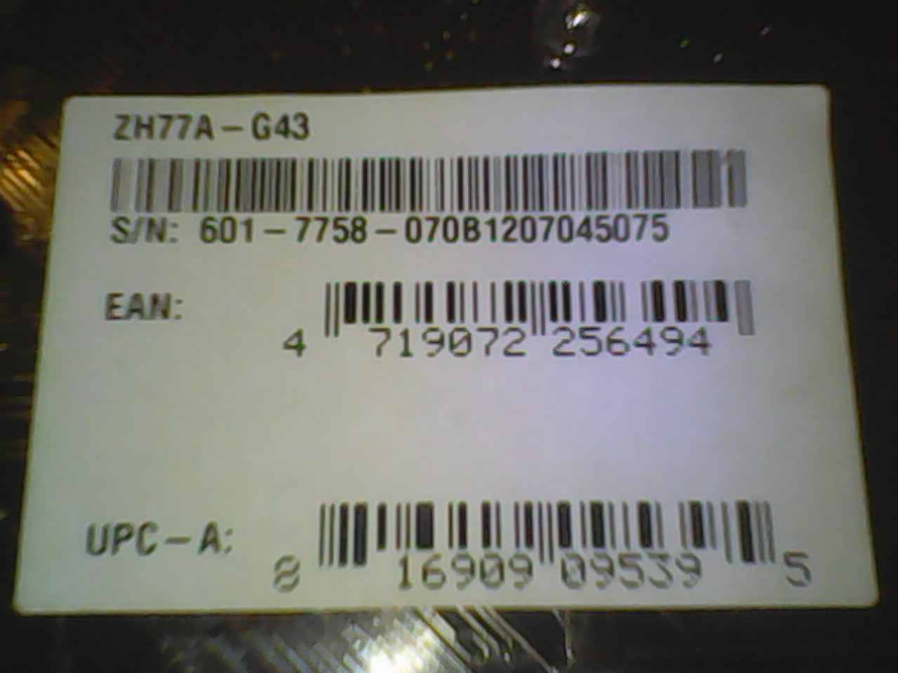
[[File:ZH77A-G43_(Back-side)SERIAL-NUMBER.jpg|none|auto]]
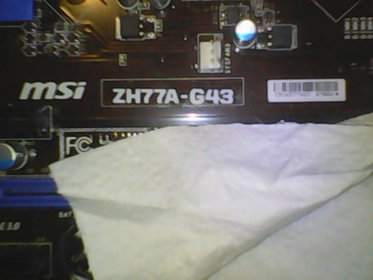
[[File:ZH77A-G43(Upper-side)numbering1.jpg|none|auto]]
[[File:ZH77A-G43(Upper-side)numbering1.jpg+model_print.jpg.zoomed-out.jpg|none|auto]]
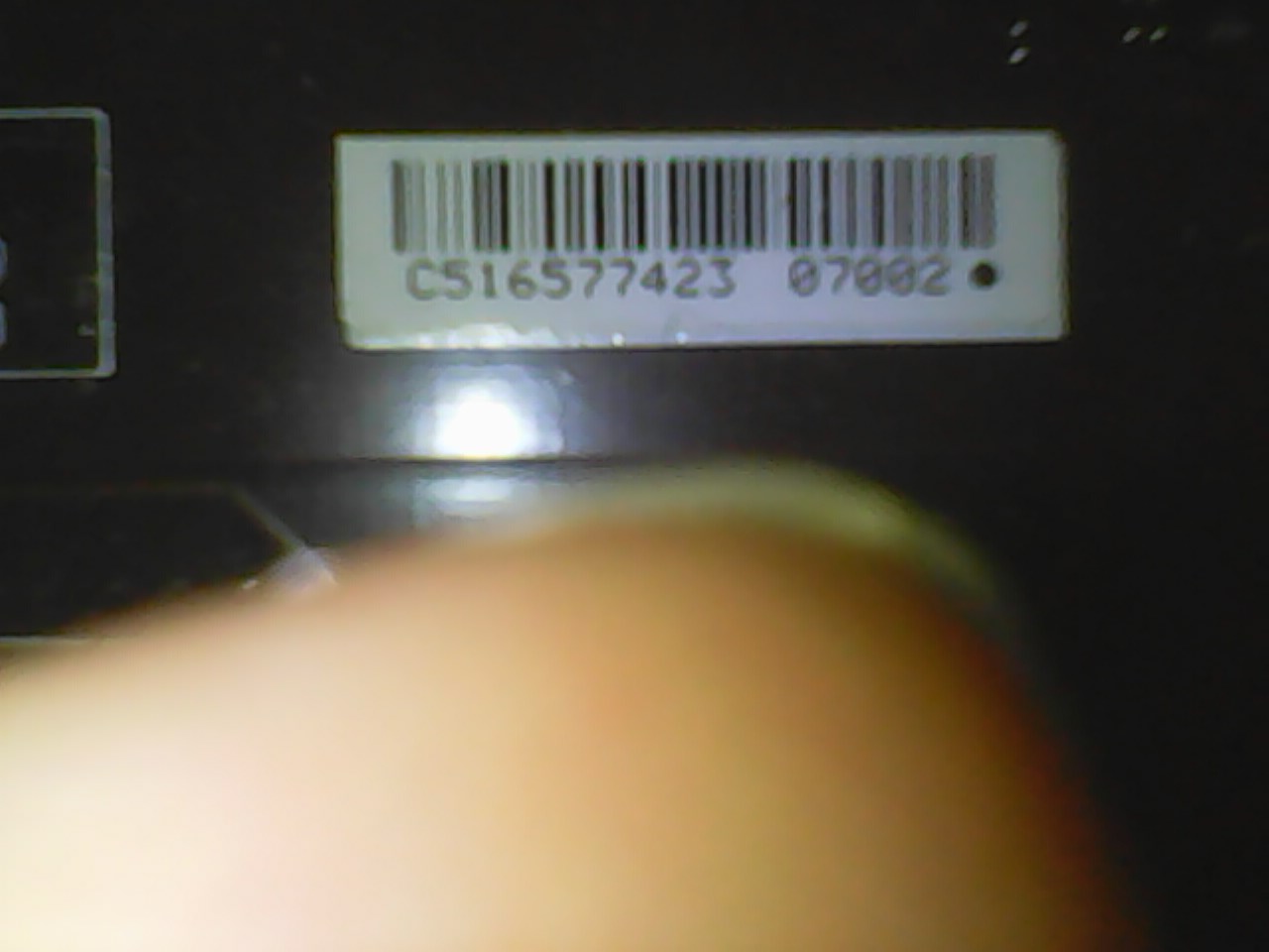
[[File:ZH77A-G43_(Upper-side)numbering2.jpg_LAN_MAC(hex).jpg|none|auto]]
-----
I don’t have any boot issues with MSI ZH77A-G43 with firmware 1.A at all.
(All later six firmware versions have fixed those memory compatibilty problems), And 1.A boots perfectly. ![]()
I meant that I (had had) boot issues, with the old 1.4 firmware (buggy) one.
—
You said my nvme mod was broken? Hm OK, I cannot decide. First updated to 1.A stock,
then flashed 1.A edited one with addded nvme-nvme-DXE with MMTool instead (UEFI-Tool would lose padding), then remodified this with UBU, for the CPU-microcodes, and probably LAN chip, nothing more.
It might be that UBU warned “checksum doesn’t match, should match AAh” (UBU 1_76_1_1 and on UBU 1.76_1_2, when updating cpu-microcodes,
and I know I had that error on one of the three LGA1155 boards, but it wasn’t on Foxconn H61M that warning-message"
so either MSI ZH77A-G43 or on the Asrock Z77/Pro4.
ZH77A-G43 boots fine with modded firmware, even though it might be bad modding according to you, and probably here where the “UBU-Aah-checksum-warning-message occured”
[Edit]I’ve send an amazon egift-card-to you.
https://www.quora.com/I-was-sent-a-gift-…rd-to-Amazon-CA
Unfortunately it’s send via amazon.de (so unit in Euros)
But according to this if I understood correctly you can still buy with it, and exchaged by USD, quite good USD-Euro-rate at time of purchase
I tried to buy via amazon.com , but I couldn’t add my EC/paydirekt banc card from my bank, as unit is in Euros and SEPA-Eurogroup-area.
I’ve got, also credit-card, but is Prepaid, I would need to load it up, that would have taken few days.
I hope this OK for you. If not, just resend it back, and I’ll buy you an USD-amazon-egift-card (in-USD-currency)
@Vincent12 - Yes, if I mentioned NVME BIOS was bad then that BIOS is bad (may not have anything to do with NVME edit itself, could solely be due to UBU microcode edit) Checksum message is normal, that is corrected on rebuild.
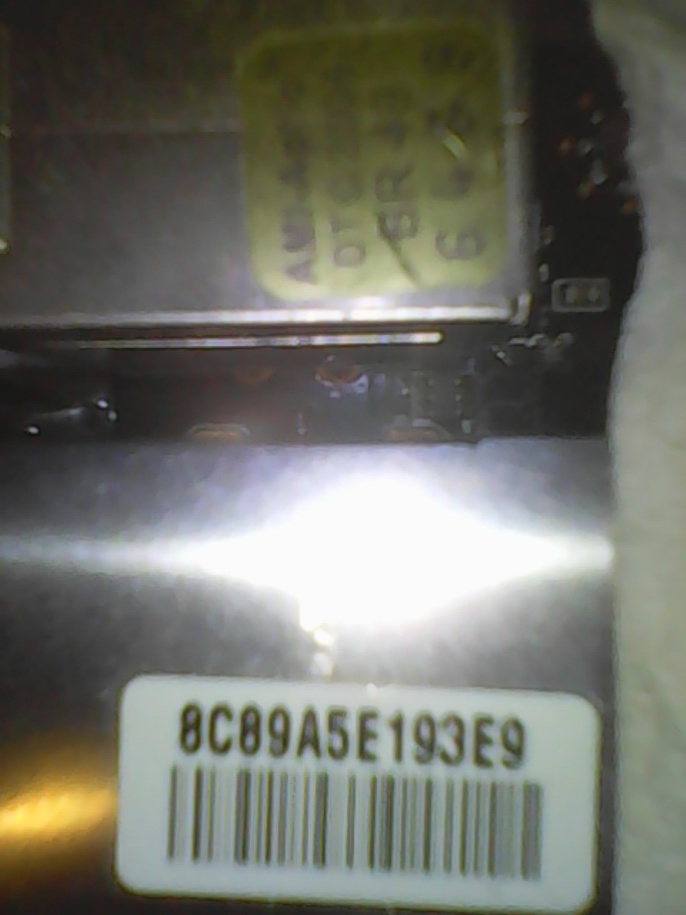
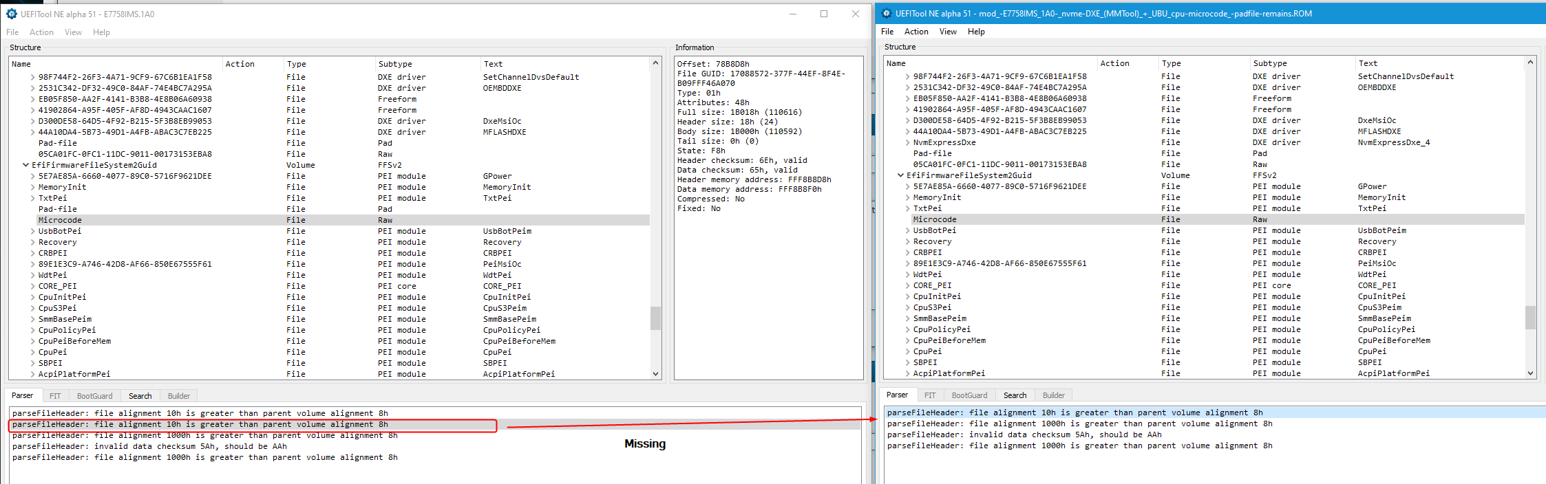
Yes, I just double-checked, assuming you wanted to use this one "mod_-E7758IMS_1A0-nvme-DXE(MMTool)_+UBU_cpu-microcode-padfile-remains"
^^ This is broken BIOS compared to stock BIOS, due to bad microcode edit at PEI volume (Padding removed), see images below vs stock
This needs done manually with MMTool if UBU does not give you alternate methods, or may need done with UEFITool (not sure, I have not done the edit myself yet to see which is OK and what is not)
If you want a properly edited 1A BIOS with NVME Mod + all microcodes updated, let me know and I can make for you.
Thanks for the above package, I will check it all out and let you know soon about the serials etc. <br />
As for the GC, we discussed in PM few days ago, I can’t use that .DE sent card, hopefully by now you’ve cancelled it and got a refund already
Sorry again for all the hassles on that 


Amazon worked, I got my refund. ![]()
Thx for the clue how to contact amazon.
—
MMTool 4.50.0.23 can open firmware “E7758IMS.1A0”, and the modded ones, but also with the stock one, MMTool crashes instantly when selecting CPU-patch-tab,
5.007 can open firmware, too, al least does NOT crash on the CPU-patch tab, but the “Delete” and “Insert” button is grayed-out.
MMTool “MMTool_5.2.0.24 (Patched)” cannot open the firmware "The Input Image is not Aptio IV"
So only way for updating CPU-microcodes would be UEFI-Tool or UBU/ maybe UBU-fix.
–
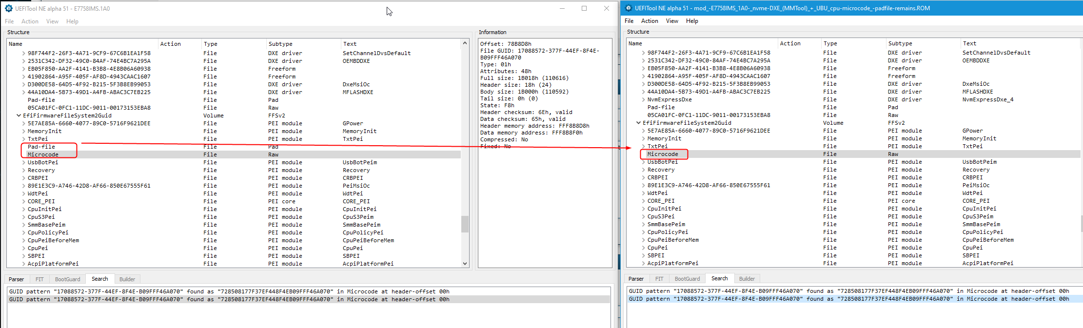
UBU updated all microcodes, and it shows revision “2F” for CPUID 206A7 for my CPU Xeon E3-1260L on MSI ZH77A-G43.
But something might be still possibly falsely modified by UBU/and or by me, as you’ve found out the padding in the microcode-section got missing.
—
Yes, could you mod the NVME-DXE and the cpu-microcodes for me,and LAN, if updating LAN was not too much?
--------
Maybe first with DXE module only, mkaing a copy of it, and attach it here? So I could compare with my own nvme_DXE-mod, that i’ve done correctly/incorrectly.
And then modifying it further with UEFI-Tool with addional cpu-microcodes?
It’s probably not easy, at least I don’t know how to do it via UEFI-Tool etc.
--------------------------------------------------
In case it might not work, no problem.
Maybe I’d ask/report on another thing my father and I have found out about s.th., it’s (principially) resolved anyway,
but might be interesting to you, but you most probably already know about that.
I’m not in a hurry. I’ll come to that later. ![]()
----
And first you’ll get the egift.
Amazon worked, I got my refund. ![]()
—
I couldn’t charge up my Prepaid-credit-card at 1st attempt (within my banc website-account), but I know the reason:
I overlooked declaring my credit-card-number in the reference bar from the Giro->Prepaid-credit-card-banc-transfer. My old VISA didn’t need that, only IBAN was needed, but I got a new MasterCard, which appears to need also my credit-card-number stated in the reference field.
(My banc has refunded me already the money automatically due to wrong/missing transfer-details. ![]()
From the 2nd attempt, now with the credit-card-number specified along, money should be there on the Prepaid-credit-card shortly.
As soon it has arrived on the Prepaid-credit-card I’ll buy and send you the egift via amazon.(com)  .
.
@Vincent12 - Great, I knew you would be able to get refund, sorry for all the hassles on that 
Yes, I can do NVME, ucodes, and LAN For you, not a problem!
This is possibly because ucodes are in PEI volume, so editing with MMTool does not always work there, or you may need to do whole module instead of using the CPU Patch tab, UEFITool edit may be required (and sometimes that is bad too), or direct hex edit.
I will check it all out and do properly, so everything remains as it should be
What do you want me to ONLY do, so you can check if you did correctly, the NVME edit only? This should be done with MMTool 4.50 only, or other much more advanced methods (Simple UEFITool edit breaks the BIOS, removes padding at end of that volume)
So, if you did edit with MMTool 4.50 it should be fine, as long as you followed the guide and inserted at correct volume (Insert As-is, not compressed)
Here is NVME edit only for your comparison. This is stock edited 1A0, do not put on with flash programmer, only flash this with M-Flash (rename to stockname.extension to M-Flash it)
http://s000.tinyupload.com/index.php?fil…676912897877405
How would I know anything about your father??? Maybe a translation issue there, or I missed something before??
So sorry you have all these hassles with the bank and stuff, that is crazy mess it sounds like!!
I guess probably all only just little confusion on missing things, since it’s not something you do all the time etc you know
Yes, if you send me anything again please be sure to do it from .com and please Don’t mention anything in the text area, especially about “Work”. Thanks is OK, but ideally no text at all is best for my sanity
Here is final mod BIOS, again this is stock modified 1A0, do not put on with programmer, only M-Flash this. UBU not used for editing, only shown in image below so you can see RealTek version changes
If you need me to redo all this with your programmer dump instead, so you can put back on with programmer let me know and I will redo.
Sorry, I was not 100% sure if you recovered this system and had it running now or not, I thought so, this is why I used stock BIOS for you to M-Flash
If this fails to boot, let me know, I will redo microcode edit with MMTool instead. If it fails, I have redone one with MMTool instead already so it’s done. ** Actually, I will post this one below (try it first, other may be broken )
I noticed this method removes another padding above a file in PEI module, but removing this one may be OK but I’m not 100% sure. Sometimes it’s fine to remove some padding, other times remove or add of padding breaks BIOS, and it’s different for all BIOS so no set rule
http://s000.tinyupload.com/index.php?fil…152765126852217
** Never mind above, here is MMTool ucode one, try first instead of above, sorry if any confusion! MMTool rebases this entire volume when doing PEI edits, this why I usually don’t like to do it, but in this case I think it’s correct way
http://s000.tinyupload.com/index.php?fil…701277088091393
And, please let me know if you need this rebuilt for programmer, so your system info is in there and original NVRAM etc, I will redo with all that in mind instead
Sorry, as mentioned, I couldn’t remember if you already have this system running again so can use M-Flash or not.
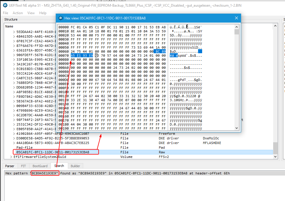
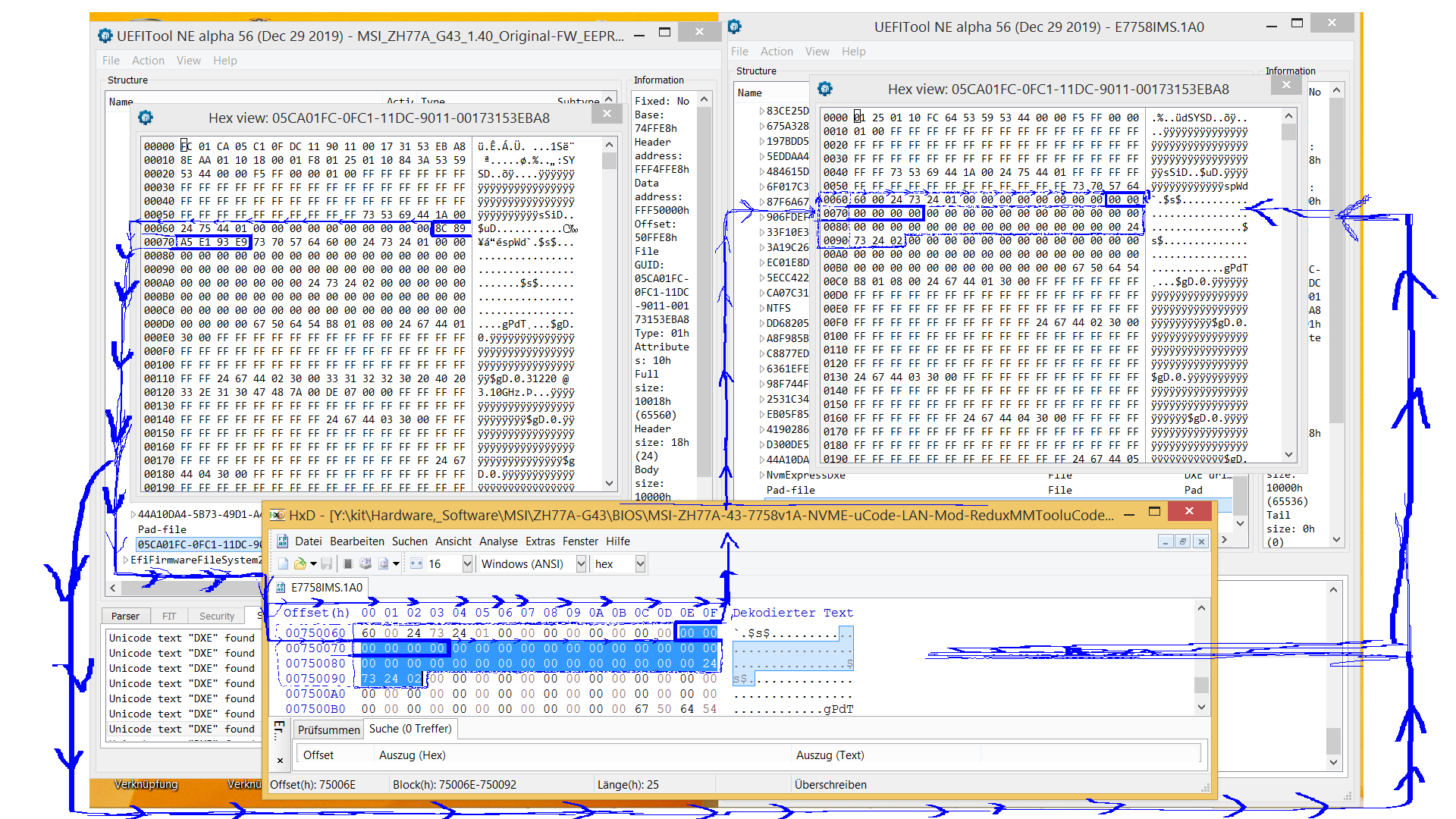
Ohh! And I checked the BIOS from both systems and ONLY find the MAC address (for each) in BIOS at GUID 05CA01FC-0FC1-11DC-9011-00173153EBA8. This is at end of main BIOS volume, below the padding file which you want to remain in place for all edits.
In a full BIOS hex search this exact location ends up being 0x750056h. Inside that module there is also other system specific info on each systems dump, but none of it matches the sticker info as is or w/ those values turned into hex.
So, I think only LAN MAC ID is stored in BIOS for this MSI Series Below is example of this modules location and how it looks in UEFITool, showing your “Working” systems BIOS/MAC ID
Good you got the money finally over someone’s other help helping me+you, as amazon was a real muddle for me, for whatever strange reason, really not so plausible to me, why it’s working for him, but not for me sending egift cards…
-----
In case if you’d help me later I’m not too much in a hurry, the mainbaord is currently at 2nd home address (30-50km away), where’d I want to replace the old one mb, with this new mainboard.
—
The mod of the MSI ZH77A-G43 mainboard appears good, I’ll test it soon.
I understood you, that there is no serial number stored in the BIOS backup, but the MAC on the sticker, correct?
But first,
It’s just that at your modded (0xA0) stock-BIOS-version of ZH77A-G43 that there is difference between both BIOS version s of 0xA0 stock (the two edited by you) you provided: MSI-ZH77A-43-7758v1A-NVME-uCode-LAN-Mod-ReduxMMTooluCode + MSI-ZH77A-43-7758v1A-NVME-uCode-LAN-Mod
that there is a difference to to the 0x1.4 (dumped)…
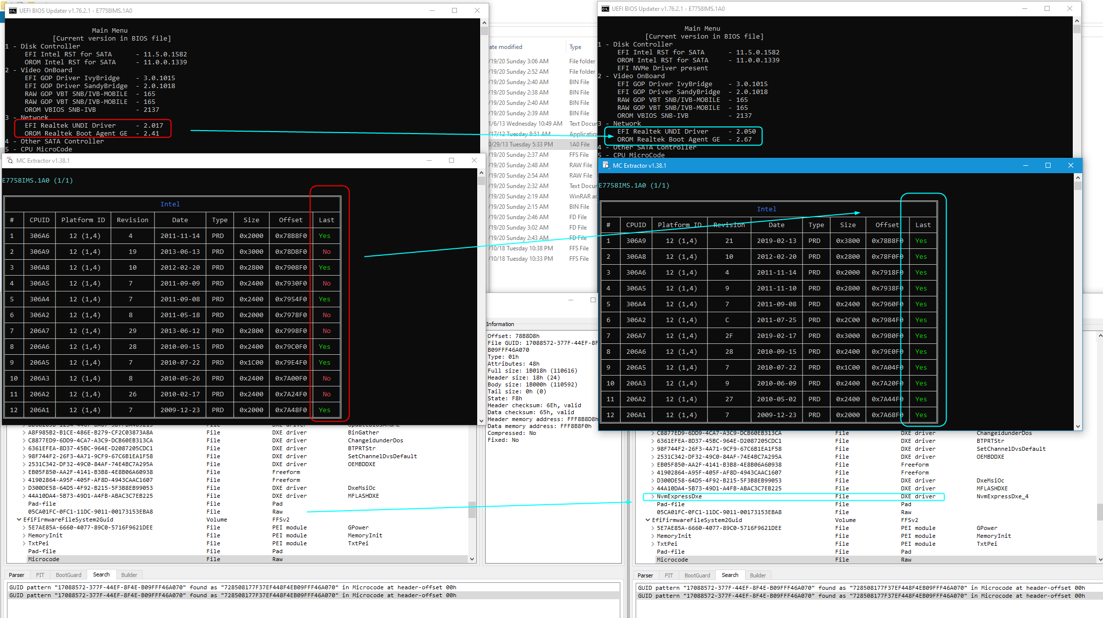
…in GUID {05CA01FC-0FC1-11DC-9011-00173153EBA8} (UEFITool GUID hex view) at offset 0x6E to 0x73 (offset 0xEE+ 0xEF+0x70+0x71+0x72+0x73 =6Bytes), you said to be for the MAC address 8C89A5E193E9 on the sticker, confirmed
In your mod this is blanc. And also a hex search in the whole modded stock (modded) 0xA0 files from you, doesn’t find "8C89A5E193E9"
So did you add the MAC address into the modded ZH77A-G43-0xA0 firmware, which I can find in the original 1.4 backuped one, as found also from the picture on the photo? (but not in the modded 0xA0 one from you)
But anything else I’m sure it’s probably all perfect.
For the other thing, If you should have some time later, and if the MAC was not added in the modded stock 0xA0 from you, could you add the MAC-address "8C89A5E193E9" to the modded firmware? (probably just a small remodify)
Or can I do it to the modded firmware myself at offset 0x6E to 0x73 (UEFI-TOOL GUID) via hexeditor, see below? So in the whole 0xA0 modded file from you to insert via HxD-hex-Editor "8C89A5E193E9" into (including) offset 0x75006E (Start) to (including) offset 0x750073 (=ending here)?
Would that be correct? If yes, is that all or more to do?
[[File:ZH77A-G43_edited_0x1A_MAC_blanc_and_in_1.4-dump_included_(differences).PNG|none|fullsize]]
–
Yes, If the MAC was not added, and you’d add it for me to the edited stock 0x1A firmware,
could you also modify it in that way and/or make another mod with all those editings, flashable with programmer?
Yes that would be great. Thx.
But first just let’s add the MAC address (if not done already), and if that works, maybe making also programmer-compatible firmware from the edited stock 0x1A one.
@Vincent12 - Yes, thank you!! Sorry it was such a long drawn out hassle, I guess we should have did what we ended up doing soon after the issues started
Right, I did not put the MAC address into the mod BIOS I sent, this will be left in place when you flash it with M-Flash (MSI Built in BIOS flash tool)
No, you can’t just edit in into same exact location on some other BIOS, as you can see the area is not same/same in both of your images above.
If you want MAC addressed changed in some programmer BIOS, you need to dump that BIOS first and send to me, then I can edit it. But, this does not work, you can’t change MAC address on system, only put back in correct one if missing.
If you are swapping boards, which I think you are doing, proper MAC address will already be in the board you will swap in, so unless it’s BIOS is already bricked you will not have to program anything.
If it’s BIOS is already bricked, once you are at that system, dump it’s BIOS and send to me, and I will fix the BIOS and send back to you for you to program back in, this way it keeps it’s original NVRAM etc
^^ If that is needed, also give me image of that sticker that has the MAC on it for this system, if you don’t have, then I can try to find but it may be impossible if BIOS is bricked too badly.
The board used for swapping, to put it into the PC-Tower is the new ZH77A-G43 mainboard, with the MAC address missing in firmware (see why a bit further below in this post).
Yes you were busy, maybe you/me forgot s.th. and/or we talk at cross purposes.
Yes I know, that’s not what I mean (and/or it just looks to me so, maybe I’m wrong). I mean editing the stock 1.A firmware file, you edited with the microcodes, putting MAC back in, and flash this with programmer as MFlash doesn’t write the MAC-address-area or that blanc area? But the edited stock firmware was not a clean way to write back with programmer? But still that the stock firmware needed to be modified by you a special way, so that it was good to go with writing with the programmer? (That’s how I understood you were the either issues from MFlash and programmer) for the files with have now.
Yes original firmware 1.4 was dumped with MFlash at first, and bit later with the programmer. The programmer dump from 1.4 we were not entirely sure if OK, as I might have later used MFlash to update. Still you have looked in the programmer 1.4 oriignal fw-dump, and we found the MAC-address in it matching to on the sticker.
Then later MAC address was deleted in the EEPROM I fear, because I had flashed the (untouched) stock 1A firmware over with programmer to EEPROM, (to recover the mainboard), before contacting.
The mainboard itself had serious boot issues, due to memory compatibility in the first place with original 1.4 firmware (see also MSI ZH77A-G43 update several later firmwares fixing memory problems), which is why I couldn’t update with MFlash to 1.A, to then get an original 1.A dump.
Then ealier when I had notified you, you explained, not to flash over a stock firmware with programmer.
(Only way here in this case to get board working.)
—
Flashing over the edited firmeware from you, with MFlash, where’s no MAC, it will result in no MAC either, (as the stock 1.A firmware currently on the EEPROM-Chip doesn’t contain any.
-----
So you couldn’t modify the 1.A stock firmware, to add the MAC address, as you did with CPU-microcodes?
[b]Why would it be important to dump the flashed 0x1A-stock firmware/and or the edited flashed one onto the chip, with programmer again, so that it would be correct one, tu put the MAC address back in, if were missing?
The clean way, if what you were proposing, as far I understood you, would be:
Flashing back 1.4 original dump (which has the MAC address). Then updating this with MFlash to 0x1A firmware.
Then doing the dump with programmer (MAC here still included). [Edit] And then reflashing with MFlash with your modified 1.A stock 1.A from you? Mflash would leave the MAC m correct?
And if I’d want optionally I can redump, to have a proper dump 1.A backup including the MAC for MFlash way?
.
But mainboard won’t boot due to memory comitibity bug in 1.4 firmware anyway, if I flash that back so I won’t be able to get an 1.A updated (original) dump. So to me it looks that problem I can’t try above way
—
[Edit]
So only option recommended in this case is modifying the stock 1.A firmware (file) a special way from you, and if possible put the MAC back in, for flashing the clean way with ext. programmer? Then redump that, and then I’d have also an 1.A MFlash good dump?
----
Sry I’m confusing. Forget about all it.
Maybe another way:
OK I think I got your point, sry took quite some time for me to understand.
1)Yes I’ll reflash firmware 1.A stock untouched one with MFlash (as you said/recommended not to use directly with programmer).
2)Then I’ll dump that with programmer.
3)Then you modify that dump with adding the MAC. Maybe you will also edit the MAC-added dump further for programmer-compatibility in case that was s.th. to do (I don’t know) .
4)Then I’ll flash that edited MAC-added dump from step 3) into with ext. programmer, as MFlash would not overwrite the MAC/blanc MAC area.
5)After that I’ll MFlash 1.A stock-edited one (you previously posted, with CPU-Microcodes, nvme and LAN-mod, which does not contain any MAC), because MFlash will leave the MAC area untouched, where I got the MAC into EEPROM with flashing the image from steps 3) and 4)
6)Optionally I can redump that with programmer, and should be valid for MFlash and/or also for programmer
I’d hope with those and/or with most described steps, I got you right this time. ![]()
On any working system, dump the BIOS with M-Flash or programmer and send to me for editing MAC, and then program back with programmer.
M-Flash will not program in MAC, at least I don’t think it would, it should leave it in place, since it’s there by default and would be left in place during M-Flash.
For the system you programmed in stock BIOS with programmer, and do not have a programmer backup of, we cannot fix the MAC address unless you have the correct one for that system on a sticker.
If you do, then dump this BIOS with programmer and send to me, I will try to put back MAC in correct place. Since you programmed stock BIOS into this one, it may not be possible, but we will try.
If you have a backup M-Flash or programmer, from this board before you programmed in stock BIOS with programmer, send me that.
MAC Address is not normally included in the BIOS that you would M-Flash, only if you want to program in a BIOS with programmer, or need to fix MAC, then it would be included.
So it sounds to me, that there was more complicated stufft to do than just adding that 12 hex-digits via hexedit into the place you found out via UEFITool NE alpha hex view at the GUD you mentioned, finding ccorresdpondig area in hex-editor (via hex search) in the firmware file, and then inserting it there, and then reflashing this.
But probably not working, as that there was more to do than just that?
So MAC address can’t be changed so easily obviously, no matter if it’s from a firmware-dump nor stock-firmware?
OK. The board is currently at 2nd home address 30-50km away. Once the next weeks I’m back there I’ll start.
OK I’d do it this way:
But basically I understood you, you just warned to not flash over a stock firmware with programmer, because MAC address, and SN (if any) gets lost. So there’s no other reason, why to use MFlash instead for stock firmware flashing correct? But there was no other advantage behind using a backup dump, compared to the stock firmware, wehn using external programmer, and no other advantage for modding, (when you have anyway a backup dump already), correct?
If yes, then I knew that myself, did expect that,
And with stock firmwares flashing over with programmer, is this a problem, mess with cleaning anything??
[Guide] Clean Dumped Intel Engine (CS)ME/(CS)TXE Regions with Data Initialization
I just was confused that you warned to use stock firmwares on programmer, even in my case,
where 1.4 was not booting,
because I anyway could just flash over a stock 1.A firmware directly with programmer to resolve most serious booting problems, so it was impossible to update to 1.A via MFlash to resolve those issues, to get an 1.A original dump, other than using the programmer to flash 1.A stock firmware directly.
So all in all there was nothing else I could do, to prevent MAC getting lost on a 1.A working firmware, if I want to get a working board. 
1.4 original one was damn buggy, (extremly unusable, not functioning in first place).
–
So those 6 steps won’t make it easier for you to edit the MAC into the firmware, even though you recommended to make a new backup dump (now with 1.A) first, for the editing?
What about Asrock MAc Tools? I’ve four versions downloaded which go for different older and newer generations. And many Asrock boards the last few years anyway use Ami and AMI Aptio v4 and V5 firmwares. Only Gigabyte on older gnerations mostly took Award, but the last few years even also uses AMI Aptio.
https://www.asrock.com/support/download/mactool.asp (2.0.18D)
Other 4 Asrock MAC-Tool versions I downloaded 1.61B; 1.17F; 2.07A; 2.16B
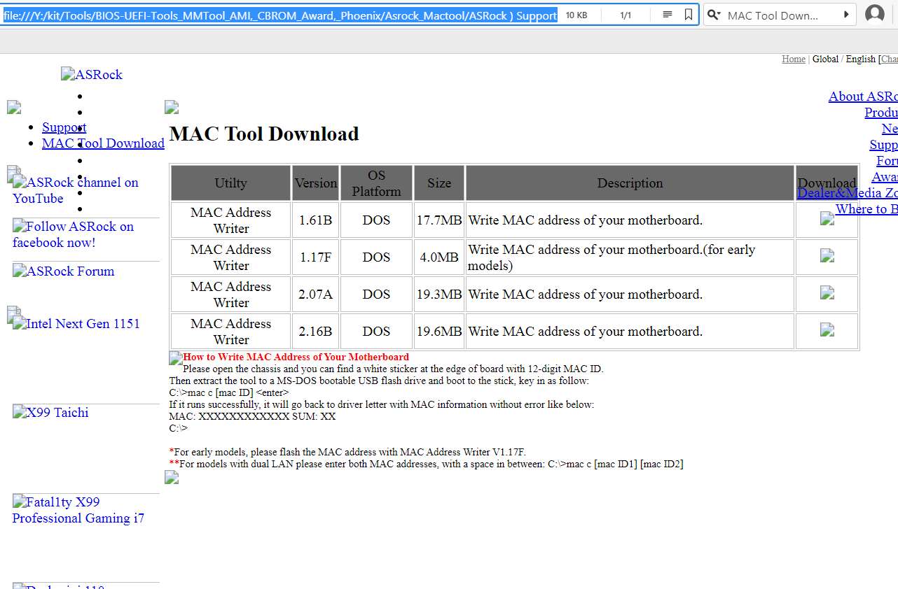
So maybe for the MSI board which has AMI Aptio 4, maybe an appropriate Asrock MAC Tool version could do it, to restore MAC into 1.A firmware?
(In the zip files are many directories of many dozens onbaord LAN chips included.)
If yes, I’ll probably just have to do the Realtek Pin mod to remove the write-lock?
(Also can you modify firmware to remove flash descriptor R/W locking? If yes such firmware will probably have to be flashed by programmer, as MFlash wouldn’t allow to overwrite FD, correct?)
Yes, I only showed you that info about MAC in regards to meaning “This is where MAC is stored” IN “This Exact BIOS” only type of thing. Due to this areas contents vary, it’s location will likely differ in all systems
MAC address cannot be “Changed” only corrected (added back in). MAC address can ONLY be the MAC address that was originally programmed to that system when it was manufactured, you can’t “change it” unless you replace the chip (This is for legal reasons)
Modding BIOS you can update stuff, change settings etc, lots can be done in a mod BIOS.
Reasons to use M-Flash vs programmer, when you don’t care about serial or MAC is that M-Flash does not require you to clip on the the chip and add more wear and tear on your clip (if it’s cheap one it will only grab hold so many times before it stops being able to grab a chip properly)
And when you use M-Flash you also are not risking shorting anything out like you are with programmer.
Unless you have a ME FW issue, then no, what you linked about ME FW has nothing to do with what we’re discussing here
I am not sure where, why etc, I would advise you to program in stock BIOS vs anything else, as you mentioned above. Maybe you misunderstood me?
I would always advise dump BIOS with programmer if programmer being used, edit that, then program back. Same for M-Flash, dump with M-Flash, edit, M-Flash back.
If you cannot boot a board, bricked BIOS, dump it with programmer, send to me to fix, then program that back. <<< Here, I think is maybe where you thought I said use stock BIOS, I didn’t, except when you said you already have used stock + Programmer to fix a bricked board (and didn’t get backup first)
^^ So in that case, then yes, stock BIOS + programmer would be your only option, unless you program in some other same model programmer dumped BIOS << This would be ideal if BIOS is bricked and you do not have backup, but DO have same exact other system + Fix MAC First
Yes, MAC tools like that may work on these systems, only you can find out by zero or FF out current known working MAC. Then use tool to try and fix, then test and see if fixed or not.
You have programmer, so Realtek Pinmod not required here. Yes, I can unlock FD for you on any BIOS, but you must then program that BIOS in with programmer and not program in any other BIOS later without first unlocking it’s FD (or replacing the FD with one I unlock for you first)
Yes, M-Flash does not usually write in FD region, so programming it in would be required (just once)
Yes as far I understood, when flashing a firmware-dump, from another computer-mainboard sample (even exact same model)
over to the other (principly) same mainbaord, if the dump was from other sample, first to clear data initialization in the somewhere in the ME firmware region. ME-analizer shows that afaik. Interesting if I remember correctly, ME analayzer even on a stoxk firmware it shows "initialized". Afaik when it was an universal-falshable firmware for all samples of syme type, it was not in an initialization state. After first boot afaik un untouched firmware in the EEPROM, never booted yet got into an initialized state, which if dump that again it would need to reprepared, correct?
Yep I just misunderstood. I just expected, you hadn’t noticed that I’d know for the reason with the backup dump already, as you reminded just few times to do backup dump. I think we were a bit crosstalking (yes you meant the MAC address of course ), it just had diffculties (with my too much) text, to explain that I had done a 1.4 backup already. But you just warned me to dump first, as you (Maybe) had to fear I could forget.
Yep firmware 1.4 was dumped wirh programmer. I also took an MFlah 1.4 dump, but here UEFI-Tool NE does show other structure than on the programmer dump (on MFlash 1.4 dump there’s no ME,BIOS-region structure visible, so MFlash dump probably the fraud one, and from programmer (principly) OK, with the 2alternating (only 1-Byte differing)checksum periods we talked about.
Thx.
Yep I’ll try with Asrock MAC Tool. So hexediting is not working? At least we found exact location via UEFITool and hexeditor in which GUID {…} in 1.4 and 1.A the MAC address is stored, at which offset. Is it possible that the MAC-address might be at another GUID in 1.A version compared to 1.4 ? (here MAC is blanc of course on the flashed stock 1.A firmware with programmer)
yes then I wouldn’t need programmer so often, but could use "FPT" without needing the Realtek mod, which could be bit risky s.times, but I have much patience etc. so not too big deal.
—
I know, MAC is unique. Evry ntwork card has its own MAC address, and if s.o changed it in the firmware on another card to the same MAC as other has, and bot network cards in same LAN, it causes networking intranet/internet issues.
Yes the MAC can only be changed, if itÄs in a programmable chip, to where you get a interface-connection established to, so that you could write in a firmware with a changed MAC-address into, correct?
/And /or you mean notpossible as in the network-chip itself (hard-wired)?
(Aynway not important to me, as just get it back, matching to as it was before.
A had that issue recently, but in a special situation. I tried to recover an SATA-USB-bridge firmware for an Asmedia ASM1153E SATA-USB-bridge chio, from a Fantec DB-ALU3e-6G SATA-6G ->USB 3.0-B +eSATA-6G enclosure.
The firmware got bricked as I flashed wrong firmware. Asmedia MPTool firmware-tool no longer detected the bridge to recover any firmware, so I had to use ext. programmer.
The problem was the SOIC-clamp in this situation at first, but mainly the EEPROM Fudan FM25F001 chip, being too near to USB-3.0-port. So I had to cut the SOIC-clamp a bit narrower, to get less wide. This was not the problem itself that it got narrower, that it wouldn’t hold.
(I had to start the putting of the SOIC-clamp to other more-open side-direction, which is away from USB-port, to attach it properly, and retry a few more times)Ribbing off a bit plastic helped, to get the attached in tolerant enough mostly rectangular-enoguh angled, without slipping off, and detecting the CHIP-ID.
But later I had to retry more often than normally here in this case, until it was attached properly.
Later the clip/clamp’s brass-contacts slipped to the inner side ca 1mm into. And then it didn’t have far enough contact with the SOIC-chip-Pins anymore, even though attached fully as before, where it still had worked.
Then I took a small "combination pliers"/engineers pliers -tool and a small thin needle. I hooked the too much to the behind movec clip’s brass/gold/plated-contacts a little bit carefully up, and the grabbed pulling with the engineer pliers the too much back-inner-moved brass/golden SOIC-clamp contact back to the outer side, only one-by-one. Worked perfectly, compared with the other new clamps, which were not yet used, contect look perfectly at identical, position Had to do that that with 6 of 8 SOP/SOIC-clip’s brass contacts. Worked perfectly like a charm without any problem.
The most issue was only not too pull too much too hard, so that it does not push the cable in behind into the clamp-body, ribbing off any cable. But this was no issue, easier than expected.
And I was more carefully with reattaching the clamping, after that did that 30 time ca, contacts haven’t slided back, not any single visible part of any Millimeter so far yet after repairing the clamp. Hehe ![]()
Programmer again get’s the Chip-ID when attaching the clip/clamp.
But anyway still not so helpful as the pirticular PCB in the SATA-USB-adapter hinders being able to write anythig to the EEPROM to recover, just reading works, but not reliable.
I’ve also replacement Fudan FM25F01 chips, (not within a circuit)
Here I get two stable Chip-IDs reading. With ICSP VC disabled one certain Chip-ID continuesly, with VCC Enabled alaways the other Chip-ID.
On the Fantec with the in-placed FM25F01, I get always the VID-reading, from the NOT-builtin-chip with "ICSP VCC (Disabled setting)". So the replacement chip might be fraud, not sn original FM25F01, and/or over reason. or the Chip ID one from ICSP Vcc enabled is just the correct one.
I’ve bough several few clamps. Just the the pricely cheap ones with 1€ per piece,inclduing with a DIP/DIL-SOIC adapter+flat cable. Works good. I’ve also a Panoma clamp, but they are overpriced.
—
What matters short circuiting. I think there can’t happen so much. VCC and GND is diagnally on the SOIC-chip very far from each other. And next to VCC-EEPROM-pin is the HOLD-Pin and Hold anyway needs to be shorted with VCC. OK next to HOLD is another-Pin which it could short-cricuit to, but rather unlikely. Well for me if the clamp had slipped off, it was entirely mostly, and I always watched the clamp, that it doesn’t get stay into a moved angular angle, which is the most problematic.
Anyway my TL86XX programmer has short-circuit and off-protect protection, and just power only when at reading/writing EEPROM-phase. Anyway when it hasn’t contact to the EEPROM pins anymore doing, the process stops immediately "Bad contact, check whether good Pin"
So that’s why I don’t fear too much, that anything happended, while the board is powered by 24pin-wire
-(Black+Green) jumper connected, only then reads CHIP-ID permanently, to read/wrte firmware.
But I would have more fear to do that with other programmer, in case it wouldn’T have that short-circuit,off-protect protection.
Yep
I just if board still booting if Id like to dump whole firmware, after I reflashed via MFlash, I need FD unlocked, to use with FPT, as MFlash on ZH77A-G43 doesn’t dump whole firmware, so needs programmer. But programmer is more risky you saying, and it’s easier with FPT, (when board still booting)
(In case I need to rewrite/redump, to have to less to use programmer, which saves time. In recsue situation when not booting, still using programmer. ![]()
ME “Initialized” means it’s in a BIOS that has been run, if it’s the same model then this is fine. Or, I can always redo and update ME FW to new clean latest version if you wanted too, not a problem
And no, there is no problem to hex edit in MAC, but you need to dump BIOS from that board first and send to me. I may not get it exact at first, IF location matters, but we’ll get there.
The only issue here is where this is stored, it’s along with other board specific info, and this differs between models, dumps, etc (updates, changes etc). But we will eventually get it proper.
Also, this may just be a “Copy” and not necessary to function, the actual MAC may be stored and used from the chip FW anyway. Either way, I need the correct MAC for the target system, if you do not have on sticker, see if you can use MAC for real or not, if you can, then run IPCONFIG /ALL from CMD prompt and get the MAC ID
No, you cannot “Change” MAC ID, this is burned into the chip. Some chips store a copy of this in their FW and if missing the LAN doesn’t work, same if that is not in LAN FW but stored and used from BIOS area (if missing doesn’t work), but you can’t “Change” the ID without replacing the chip.
Short can happen in board or programmer too, not just the clip itself, so least you use as possible is best. Yes, this probably more of a concern with cheaper programmers though
“Doesn’t dump whole firmware” doesn’t necessarily mean you can’t use FPT or M-Flash etc.
This only means that region may be locked so you can’t read/write it, unless you unlock FD first, otherwise you can dump/reflash as-is and that region will just be skipped, with FPT you can direct it to flash by region only, and that is best way to do it anyway
If FD needs unlocked, then yes, at least one dump and edit/reflash with programmer would be needed (or pinmod instead) then after that you could read/write all regions with FPT
Checked"ipconfig" and in the "System information" section in firmware, the MAC address from the sticker is listed. (Even though in the firmware in EEPROM the MAC got missing from flashing stock 1.A firmware with programmer)
I’ve made a dump from 1.A firmware from ZH77A-G43 mainboard, attached below, as you requested (see below)
Didn’t need putting temporarily any jumper addionally at all on the PWR and reset pins with the 1.A firmware.
I did it 40 times all in all, to see behaviour and how reliable. At every ca. 6th dump I get a different checksum, the rest 5 redumps in that period are all identical (checksum: sha256sum: 253152d1a0c650bc3b006e8af713ed0b1d32c7786ebbf70dc53b6731753129dc).
Now there was not any tweo-checksum pattern phenomenom as I had before on 1.4 firmware, all rest normal.
All rest ca. 35 times tested redumping also identical (253152d1a0c650bc3b006e8af713ed0b1d32c7786ebbf70dc53b6731753129dc), (only evey ca. 6th. time a new random different checksum pattern.). Tested here with "ICSP VCC (dis)abled".
It was interestingly more reliable with "ICSP VCC (dis)abled" than with "ICSP VCC enabled". With enabled, only ca. every one up to 3rd time I got (253152d1a0c650bc3b006e8af713ed0b1d32c7786ebbf70dc53b6731753129dc), in between next tries more random different checksum pattern, than with ICSP (disabled)=here=better
So dump with checksum sha256: 253152d1a0c650bc3b006e8af713ed0b1d32c7786ebbf70dc53b6731753129dc) within zip, should be good.
Attached:
MSI_ZH77A_G43_1.A0_MFlash_reflashed-FW_EEPROM-Backup_TL866II_Plus_-Verify-OK.zip
---------------------------------------------------------------
Below I attempted MAC hexediting, I hope it’s done correct way. Could you check?
In the 1.4 firmware dump in UEFITool at GUID {05CA01FC-0FC1-…} you found and showed me MAC address from the sticker label, within the long hex string: …73 53 69 44 1A 00 24 75 44 01 00 00 00 00 00 00 00 00 00 00 8C 89 A5 E1 93 E9 73 70 57 64 60 00 24 73 24 01…
In 1.A dump I also found that text string like in 1.4 dump, only just the "00" replaced by "FF" and the MAC address missing:
1.4 original-fw-dump
0x "…73 53 69 44 1A 00 24 75 44 01 00 00 00 00 00 00 00 00 00 00 8C 89 A5 E1 93 E9 73 70 57 64 60 00 24 73 24 01…"
1.A stock firmware reflashed back with ext. programmer, then reflashed with 1.A stock with MFlash (ME region + BIOS) -dump:
0x "…73 53 69 44 1A 00 24 75 44 01 FF FF FF FF FF FF FF FF FF FF FF FF FF FF FF FF 73 70 57 64 60 00 24 73 24 01…"
–
I’ve hexedited the MAC into the last six (6) Bytes with * FF, so the last 6 bytes before the (0x 73 70 57 64 … …) in the 1.A dump firmware, so that I inserted it at same corresponding position of the both nearly same long hex strings in the 1.A firmware as in 1.4 firmware:
1.A stock firmware reflashed back with ext. programmer, then reflashed with 1.A stock with MFlash (ME region + BIOS) -dump - MAC hex values hexedited into:
0x "…73 53 69 44 1A 00 24 75 44 01 FF FF FF FF FF FF FF FF FF FF 8C 89 A5 E1 93 E9 73 70 57 64 60 00 24 73 24 01…"
Interestingly in UEFI-Tool at GUID {05CA01FC-0FC1-…}the position of the found long text string appears a little bit shifted compared from 1.4 firmware dump and 1.A firmware dump, visible in picture below (on the left: UEFI-Tool), (as still in hexeditor the long nearly matching text string is shown at identical offsets, when opening 1.4 dump and 1.A dump in hexeditor)
See picture, where I hexedited the MAC into (see picture on the right bottom the Red letters)
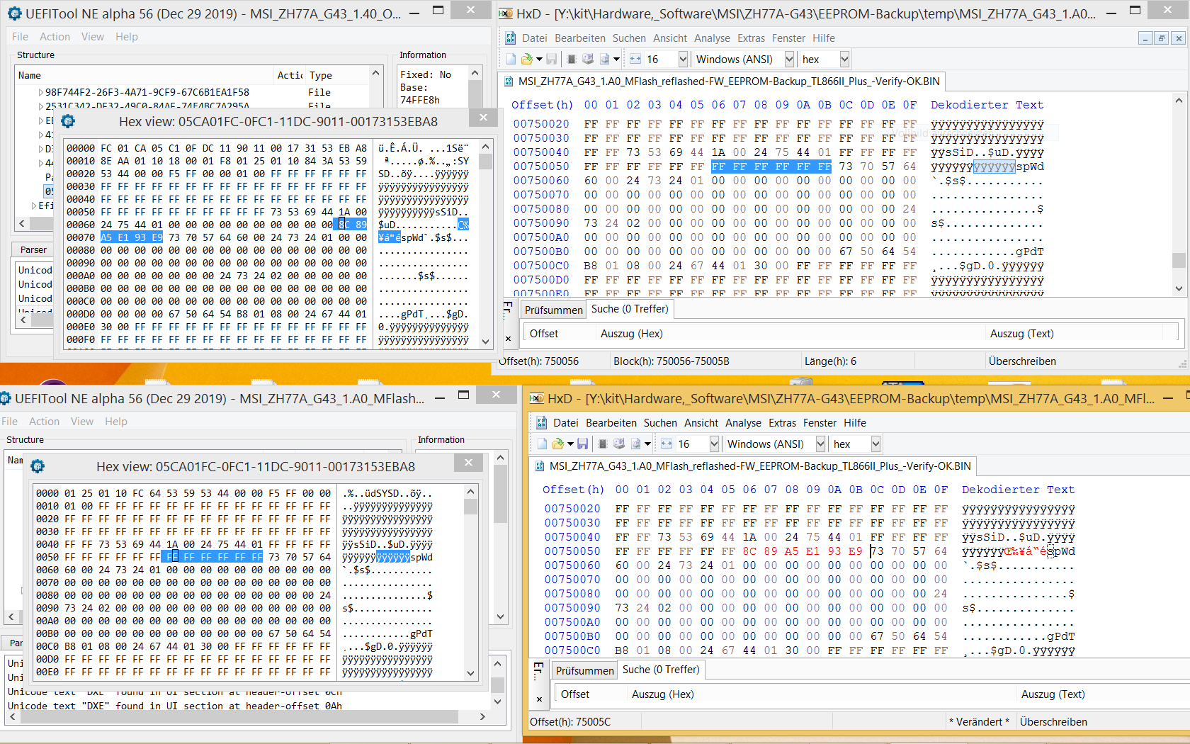
And see result:
"MSI_ZH77A_G43_1.A0_MFlash_reflashed-FW_EEPROM-Backup_TL866II_Plus_-Verify-OK-MAC-hexedit.zip"
- compared to
MSI_ZH77A_G43_1.A0_MFlash_reflashed-FW_EEPROM-Backup_TL866II_Plus-Verify-OK.zip
Is this correctly hexedited the MAC at correct place, and if yes, more to modify?
MSI_ZH77A_G43_1.A0_MFlash_reflashed-FW_EEPROM-Backup_TL866II_Plus_-Verify-OK.zip (5.43 MB)
Tell me MAC you want in, and link ONLY that BIOS (1x copy) and I will see if it should go in same place, if not then where etc (probably not same)
Actually, what you have there at the end may be OK, good guessing
I can’t say for sure 100% without looking at BIOS, but since you said MAC is already visible without this (and I assume Ethernet LAN functions, correct?) Then this doesn’t really matter too much to have to be exact.