I have an Asus X541NA laptop that uses the Intel Apollo Lake SoC and I want to upgrade the TXE firmware from version 3.1.65.2317 to version 3.1.76.2356.
Since Intel CSTXE v3 does not have a FWUpdate tool, and since my understanding is that the Apollo Lake uses an Integrated Firmware Image (IFWI), I am wondering what the process for this update might be.
My firmware flash chip is an SPI Winbond 25Q64FW. Having had the mainboard out, I can access it easily enough to attach my programmer to it if I need to.
What is the process for updating the TXE3 inside of an IFWI?
I have read the following guides here as reference, but I have doubts as to any of them addressing specifically what I am trying to do.
What I have read so far:
Intel Trusted Execution Engine: Drivers, Firmware & System Tools
Intel (CS)ME, CS(TXE), CS(SPS), PMC, PHY & PCHC: Firmware Repositories
Guide-How To: Clean Dumped Intel Engine (CS)ME/(CS)TXE Regions with Data Initialization
as well as a few Intel specific documents:
Apollo Lake Platform - Intel®Trusted Execution Engine (Intel®TXE) Firmware Bring-Up Guide
Apollo Lake SoC SPI and Signed Master Image Profile (SMIP)
To be clear, I am not asking for somebody to prepare a firmware image for me, but rather, explain the overview of the process so I can do it.
Thank you in advance.
Chas
So if I understand this correctly, this is what I think the overview is:
- dump the contents of the SPI chip using a programmer
- load the dump into the flash image tool
- select the correct CSTXE image, which in my case is 3.1.76.2356_B_PRD_EXTR
- set the SMIP signing key to the dummy key created with: openssl.exe genrsa --out dummy.pem 2048
- make sure that "Verify manifest signing keys against the OEM Key Manifest" is set to "No"
- build the image
- write the image back using the programmer
Here are my main questions and concerns for the moment:
1) What utility can I use to verify that the board specific data was preserved in this process? Something similar to FD44 editor perhaps? As FD44 editor does not seem to work with the dump.
2) Are there any runtime checks within the Intel ME that will be affected by the "Verify manifest signing keys against the OEM Key Manifest" being set to "No"?
3) Since I currently do not have write access with FPT and I have the Realtek ALC3251, at some point I think it might be interesting to try asserting GPIO_118 (Flash descriptor override strap) HIGH during the rising edge of RSM_RST_N. aka pinmod, but I have not been able to locate a datasheet for the ALC3251.
Obviously #3 is not a major concern with a programmer available, but I am interested in any future comments on this as I would be interested in this method as it applies to the Asus X541NA.
@ChasW Procedure seems correct.
1.) No utility I know of. Otherwise search for mac/ serial/ UUID/ … with hex editor/ in UEFItoolNE and compare before/ after. But: Flash first for checking if image is working, possibly missing info can be added later.
3.) Your FD is set to FFF for both read/write TXE and CPU/Bios, but there will be other protections, BootGuard is enabled in ME, for example. Did otherswise read several places that these bioses are very hard to edit, UEFitool will often (always?) brick. So you’d possibly can’t avoid use of programmer anyway.
Yes. I’ve been scanning through the bios region with HxD and UEFItool to see what variables I are present. Initially I tried some basic tests since I want to have a BIOS backup before comitting any changes that might brick.
For example:
fptw64.exe -d biosreg.bin -bios
works and yields a legible bios region that can be parsed for most of the variables expected to be in that region. i.e. serial number, bios version and date, but not mac address,
but:
fptw64.exe -f biosreg.bin -bios
yields the following error:
Error 559: EOM prevents IFWI Prepare to Update from completing
FPT Operation Failed.
I assume the error is due to flash descriptor security hence one of the needs for dumping with a programmer, but before I even attach one to the chip, I need to be certain I have all of the essential board specific info saved first. I know it is rare, but handling the chip i.e. attaching programmer clip to it, or desoldering it and plugging it into a zif socket can result in corruption and data loss, which I would very much like to avoid, making the pinmod option appealing for an initial backup dump.
I am basically only aware of the following board specifics as they are visible through the BIOS Setup program:
Bios Version
GOP Version
EC Version
S/N
MAC
Firmware Date
Firmware Time
All of the above seem to be visible in the bios region dump from FPT, except for the mac address. Since this is integrated firmware, I somewhat expected mac to be in there, but it is not that I can see, unless it is encoded in some way I am not aware of. Im getting closer to being able to do this backup and update, but not quite where I want to be just yet. Obviously getting the various MACs is easy within the OS or Setup program, but putting back into the firmware image is another story as I do not see a way directly supported by a utility such as FIT.
Of course, it is what I am not aware of that concerns me.
I have doubts as to whether this update is even possible with BootGuard enabled while "Verify manifest signing keys against the OEM Key Manifest" is set to "No".
Only reference I could find to this error: Trying to change the power throttling limit on Acer Spin Pentium N5000 (4)
First things first- try to create a working image
Otherwise: Trying to flash back the bios region (fpt -f …) without having a full dump/ backup seems pretty much like looking for adventures. I’d consider that right the opposite of "but before I even attach one to the chip, I need to be certain I have all of the essential board specific info saved first. I know it is rare, but handling the chip i.e. attaching programmer clip to it, or desoldering it and plugging it into a zif socket can result in corruption and data loss, which I would very much like to avoid, …"
Look into your complete bios with UefitoolNE or check the map written by FIT, both show that there’s no clear region for bios and me/cse- those are mixed into each other. Connecting a CH341 flasher to your bios chip for a backup is quite safe (beware of 1.8V chips). And with a backup of the complete chip you have all the information fixed you’d ever could need at a later time.
Did you ever try a complete dump of your complete firmware (“fpt -d backup.rom”)?
----------- --------- ------------ ---------
00000000 007FFFFF 00800000 Full Flash Image
00000014 00000017 00000004 FLMAP0 - Flash Map 0 Register
00000018 0000001B 00000004 FLMAP1 - Flash Map 1 Register
0000001C 0000001F 00000004 FLMAP2 - Flash Map 2 Register
00000030 0000003B 0000000C FCBA - Flash Component Registers
00000040 00000043 00000004 FLREG0 - Flash Region 0 (Flash Descriptor) Register
00000044 00000047 00000004 FLREG1 - Flash Region 1 (IFWI) Register
00000048 0000004B 00000004 FLREG2 - Flash Region 2 (Intel(R) TXE) Register
00000050 00000053 00000004 FLREG4 - Flash Region 4 (Platform Data) Register
00000054 00000057 00000004 FLREG5 - Flash Region 5 (Device Expansion) Register
00000060 00000063 00000004 FLREG8 - Flash Region 8 (Embedded Controller) Register
00000080 00000083 00000004 FLMSTR1 - Flash Master 1 (Host CPU/BIOS)
00000084 00000087 00000004 FLMSTR2 - Flash Master 2 (Intel(R) TXE)
00000100 000002FF 00000200 FPSBA - SoC Straps (Including Padding)
00000DF0 00000EFF 00000110 VSCC Table
00000DF0 00000DF7 00000008 VsccEntry0
00001000 00358FFF 00358000 Boot Partition 1
00001000 0014CFFF 0014C000 Primary Boot Partition
00001200 0000120F 00000010 IFP Overrides Partition
00001210 00001317 00000108 Unified Emulation Partition (UEP)
00002000 00005FFF 00004000 OEM SMIP Partition
00006000 00010FFF 0000B000 CSE RBE Partition
00011000 00020FFF 00010000 PMCP
00021000 00083FFF 00063000 CSE BUP Partition
00084000 0008CFFF 00009000 uCode Partition
0008D000 0014AFFF 000BE000 IBB Partition
0014B000 0014CFFF 00002000 Debug Token Partition
0014D000 00358FFF 0020C000 Secondary Boot Partition
00256000 00358FFF 00103000 CSE Main Partition
00359000 0077DFFF 00425000 Boot Partition 2
00359000 0077DFFF 00425000 Secondary Boot Partition
003C1000 0077DFFF 003BD000 OBB Partition
0077E000 0077F000 00001001 TXE Data Region
Yes, I am waiting for a level translator for the flash chip’s programmer before I can begin.
Yes, that was the first thing I did actually, which is when I was first made aware of the flash descriptor status, which currently is:
BIOS access table:
Read Write
Desc Yes No
BIOS Yes Yes
ME No No
GbE No No
PDR No No
EC No No
Here is the result for:
fptw64.exe -d dump.bin
Error 318: The host CPU does not have read access to the target flash area. To enable read access for this operation you must modify the descriptor settings to give host access to this region.
Yes, I understand. The context for my statement was simply being aware of which board specifics were to be preserved in terms of a utility that provided a user-friendly interface for updating an IFWI, not that the partial bios region dump was actually that. At that point, I was simply testing whether or not I could even write back that region.
I am aware of the flash chips’s voltage levels for the winbond W25Q64FW and you are right, it is 1.8V. I should have the level translator today and some spare W25Q64FW 's in SOIC-8 early next week to experiement with the programmer before attaching to the flash chip on the mainboard.
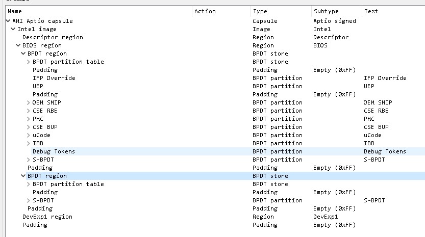
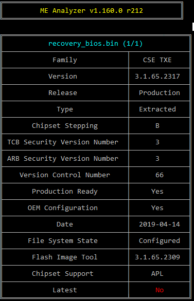
I realize there is no clear region. I think that is the nature of what IFWI means. Here is a partial the output from MEA of the fptw64.exe -d biosreg.bin -bios which demonstrates that.
Your point is still well taken, however, as it is central to my concern. The end goal is to update the latest TXE3 into the flash bios. However, I am not Asus and therefore not in possession of the private signing key. So the question which still stands is what happens when Boot Guard is left at Profile 2 VM with the dummy signing key and oem verification turned off? ![]()
It would not make sense to do the firmware update to reduce system vulnerabiliy only to introduce another vulnerability. i.e. legacy Boot Guard
Once BG is set properly (in FPF), you cannot change it no matter what you adjust in CSTXE settings via FIT so that’s not an issue. BG covers only some BIOS sections of the IFWI, not CSTXE. You can check if BG has been set properly via TXEInfo.
The dummy key is used temporarily to allow FIT to re-build the IFWI with an updated and/or cleaned CSTXE (depending on what one wants to do). The actual SMIP signing key is placed back at a latter step of the Cleanup Guide.
And yes, for CSTXE 3-4, you need to use the CleanUp Guide to update the firmware. If your OEM provides a full SPI/IFWI image (FD + IFWI 2.0 + CSTXE Data/DevExp) then you can use that as a basis of the guide. If they don’t, you’ll have to dump your own. The process remains the same either way because the guide can be used for both cleaning and updating.
In this case though, ASUS does provide a full SPI/IFWI image, once you remove the 0x800 sized AMI Capsule at the top via UEFITool NE. So there is no need to dump your own. The problem is flashing it back as you’ve correctly identified. I don’t know what method ASUS uses but it is almost certainly “Capsule” because “DnX” is not included in the SPI image. In that case, you can use the normal ASUS updater with the only problem being the AMI Capsule which I presume will be invalid once you copy it back after the modification/update. You can try to bring it back and check if ASUS verifies it while flashing. If they do, you’ll have to use FPT (not possible at locked FD) or ultimately a programmer.
If I were to try to use this instead of my own full SPI/IFWI image as the basis for the CSTXE update, wouldn’t the S/N and MAC address be discarded?
If you use it with FPT or a programmer, yes. If you use it via whatever updater ASUS has, then no. Otherwise you would lose BIOS info at every BIOS update from ASUS. If you can use FPT or a programmer then it stands to reason to dump your SPI/IFWI image first. It’s a generally good practice to keep backups before trying stuff like that either way.
My understanding is, and I base this only on what I have read, I do not know for certain, is that the Asus updater parses and skips over blocks to preserve existing board specific information. Again, I could be mistaken. I have no personal knowledge other than what I have read on these forums.
This is the plan. I will follow up here once I have managed to do so.
I am comfortable copying and pasting with HxD as well as using ME Analyzer, but my concern is that simply copying the SMIP entry from original to outimage will still trigger a security mechanism, but I certainly look forward to finding out! ![]()
Thank you for the assist.
No, no. There is no way the official ASUS BIOS updating procedure overwrites board info within the BIOS. Otherwise their customers would not be able to update without losing unique board info. The ASUS updater could for example leave the BIOS NVRAM as it is and re-flash the rest of the volumes as necessary.
It won’t. If done right, the SMIP dummy method has been tested successfully multiple times since 2016. It’s basically a workaround for FIT to allow re-building without the OEM private key, nothing else.
Anyway, once you get the programmer you’ll certainly be able to update the firmware without an issue. 
We may be having a slight miscommunication on this point. I apologize for my part in that. Nobody is saying that the ASUS BIOS updating procedure overwrites board info. As I said, it parses and skips. You had indicated that using the ASUS fw image because it was a full SPI/IFWI i.e.
and my point is that if you do not dump your own, but rather use the full SPI/IFWI ASUS fw image as you suggested, updated with the CXTE3 firmware with FIT, using the cleaning guide procedure for the signing then flashing the chip back with a programmer would overwrite the board info within the BIOS.
So to clarify, and I truly appreciate your time and patience, for which case are you saying that you can use ASUS’s full SPI/IFWI image within the context of a CXTE3 firmware update instead of a full dump? Are you saying that I will be able to use ASUS EZ Update in some way with the modified SPI/IFWI image if I add it back to a AMI Capsule format?
This is good news!
It depends on what you want to do. If you use FPT or programmer, you need to dump your full SPI chip image (8MB) and work on that to preserve BIOS NVRAM. But for people who have a bricked system for instance, being able to get a full SPI/IFWI image from the OEM is very helpful because in that case it is more important to make it work again than to not see some serial numbers. That’s why I mentioned it as an option even if it does not apply to your case.
If you use ASUS EZ Update, you should use the full (8MB) stock SPI/IFWI from the website and work on that. The problem is the AMI Capsule which will probably be invalid after the modification (remove it, guide, put it back). You can check though, as I don’t know if it is checked or what data it covers exactly.
Hopefully that clears things up.
Perfectly, thank you.
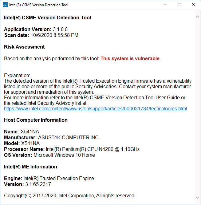
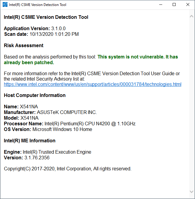
This procedure seems to have worked for me.
At least one vulnerability was patched and my board specific settings were preserved.
Here are before and after screenshots from the Intel CSME_Version_Detection_Tool_Windows.
[[File:2020-10-06 21_00_22-Intel(R) CSME Version Detection Tool - 3.1.65.2317.png|none|auto]][[File:2020-10-13 13_01_32-Intel(R) CSME Version Detection Tool - 3.1.76.2356.png|none|auto]]
Thank you to everyone who commented on this thread, worked on the Guide-How To: Clean Dumped Intel Engine (CS)ME/(CS)TXE Regions with Data Initialization, as well as the maintainers of this site for which my firmware update likely would never have happened.
If you are thinking of performing this update yourself, here are some critical considerations:
-Have a programmer on hand.
-Be aware of the programmer’s output levels. You may need to modify your programmer as I did if it is the CH341A to make sure it outputs 3.3V.
-Be aware of the flash chip on your mainboard, its orientation such that will it accept a clip connector, and the chip’s voltage. Mine was 1.8V, so I had to use an adapter fixture.
-Read all of the guides mentioned in this thread.
Here is the summary of the steps I took for the logs:
Updating the Intel TXE3 firmware on an Asus X541NA with the Apollo Lake SOC
Using this guide:
Guide-How To: Clean Dumped Intel Engine (CS)ME/(CS)TXE Regions with Data Initialization
as a general reference at section: D4. CSME 11 - 14 & CSTXE 3 - 4
[Guide] Clean Dumped Intel Engine (CS)ME/(CS)TXE Regions with Data Initialization
Using OpenSSL from:
https://slproweb.com/products/Win32OpenSSL.html
Step I - Intel Flash Image Tool
1) Dump contents of the flash chip using a programmer. In my case the chip is:
W25Q64FW (1.8V), ID:0xEF6017, Size: 8192KB (65536Kb)
2) Load the dump into Intel Flash Image Tool (FIT).
Note that my board selection was Intel(R) Apollo Lake and the Target Type should be SPI.
3) Under flash layout, under Intel(R) TXE Binary File, under Value, browse for and select the up to date TXE3 binary which for this case is: 3.1.76.2356_B_PRD_EXTR.bin
4) With Win64OpenSSL_Light-1_1_1h installed, execute the following to generate a dummy SMIP signing key which will allow FIT to build an image: openssl.exe genrsa --out dummy.pem 2048
5) Under platform integrity, under SMIP Signing Key, under Value, browse to and select the dummy.pem created from the previous step.
6) Under build settings, under image build settings, under Intel(r) Manifest Extension Utility Path, under Value, browse for and select: Intel CSTXE System Tools v3 r10\Manifest Extension Utility\WIN32\meu.exe
7) Under build settings, under image build settings, under Signing Tool Path, under Value, browse for and select: openssl.exe
8) Under build settings, under image build settings, under Verify manifest signing keys against the OEM Key Manifest, under Value, select No.
9) Under build settings, under image build settings, under Output Path, under Value, specify the output image name.
10) To unlock Write Access for utilities like Intel Flash Programming Tool (FPT), set the following:
Under Host CPU/Bios Master Access, under Host CPU/BIOS Write Access, under Value, change 0x002 to 0xFFF.
Under Host CPU/Bios Master Access, under Host CPU/BIOS Read Access, under Value, change 0x003 to 0xFFF.
Under Intel(R)TXE Master Access, under Intel(R)TXE Write Access, under Value, change 0x024 to 0xFFF.
Under Intel(R)TXE Master Access, under Intel(R)TXE Read Access, under Value, change 0x027 to 0xFFF.
10) Save the XML file.
11) Build the image and verify that there were no errors.
Step II - ME Analyzer
1) Follow from Step 13 from section D4. CSME 11 - 14 & CSTXE 3 - 4 from the Guide Referenced Above.
Drag & drop the dumped SPI/BIOS image you want to clean at ME Analyzer and at Option(s) enter “-dfpt” parameter.
Note the SMIP partition’s “Start” offset & “Size” which in this case are 0x2000 and 0x4000 respectively.
Do the same for the “outimage.bin” file. The SMIP “Start” offset & “Size” of both SPI/BIOS images are usually the same.
Using a hex editor copy the region from 0x2000 to 0x6000 from the original dump to the new binary image. I used HxD to do this.
Verify the new image in ME Analyzer as per the guide.
Step III - Intel Flash Programming Tool
Flash the newly updated image using the programmer.
Run: Flash Programming Tool with command fpt -greset and wait for the system to reset.
Regards,
Chas