[Guide] Using CH341A-based programmer to flash SPI EEPROM

There are many different SPI programmers on the market right now and almost any microcontroller-based board can be used as one, but this time I will speak about one of the cheapest programmers to date - CH341A-based.
They are sold from various chinese suppliers for about 4 euro and are capable of flashing with both SPI and I2C chips, working as USB-TTL adapter and USB-I2C bridge.
In this guide I will only cover the SPI part of functionality because this is what you need to flash modified or restore original firmware on all modern PCs.

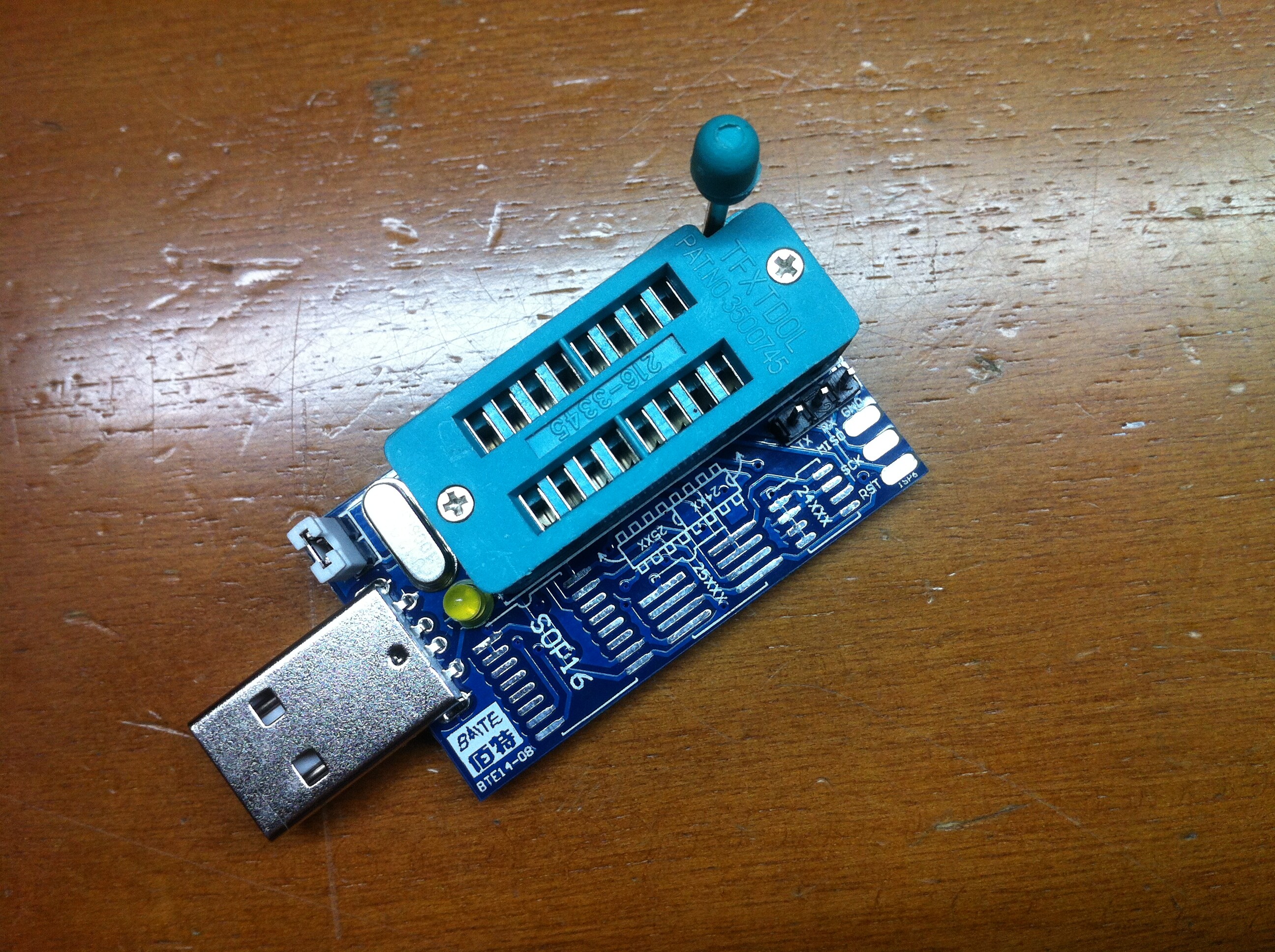
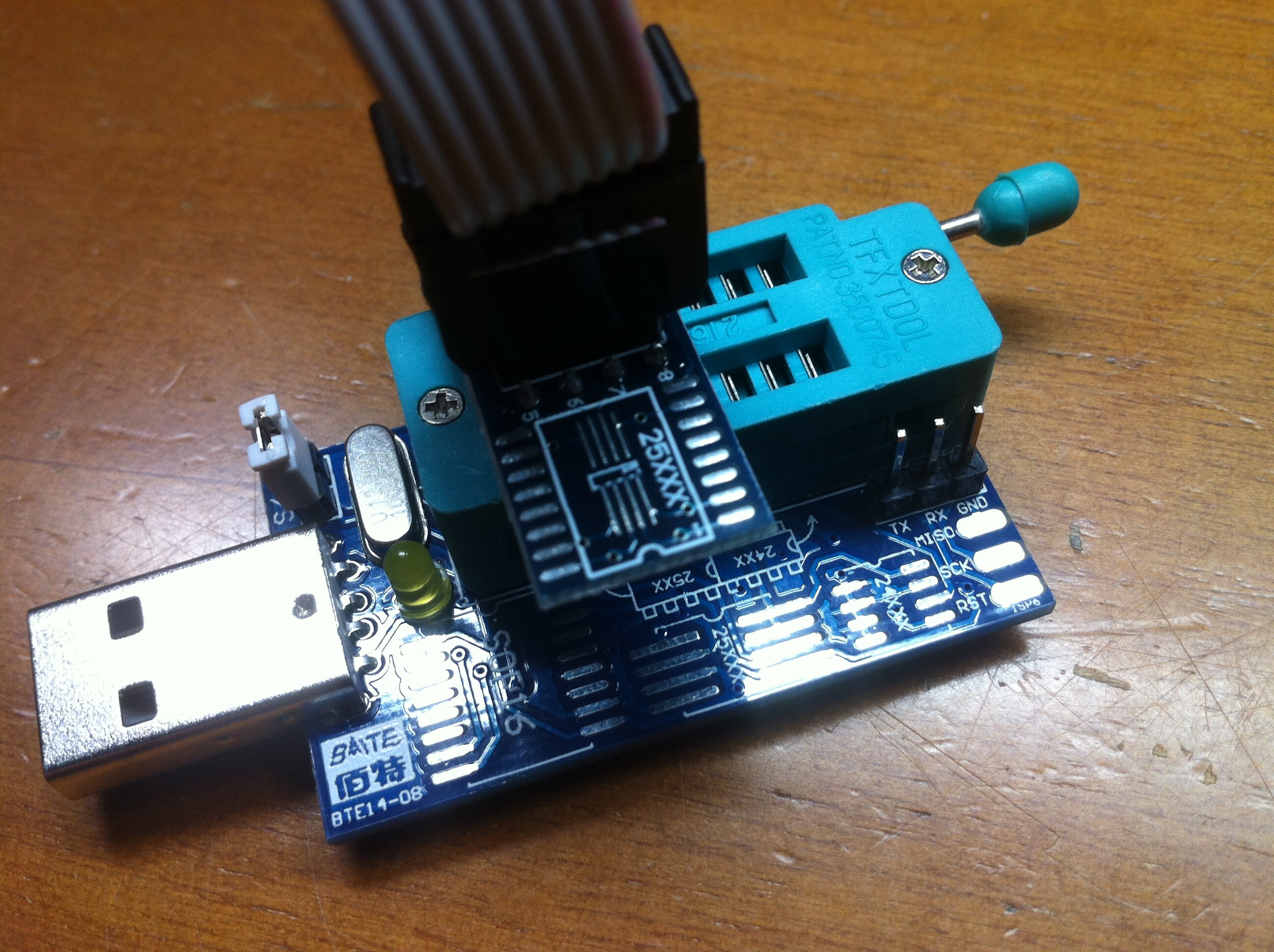
0. Get yourself a CH341A-based programmer. They are various in PCB designs and features, but all of them can flash SPI chips, so buy any model suitable for your needs. I’ve bought this one.
1. Download the software. Windows-version is attached to this post, version for Linux is here. Required drivers will be installed automatically (if not, just google for them).
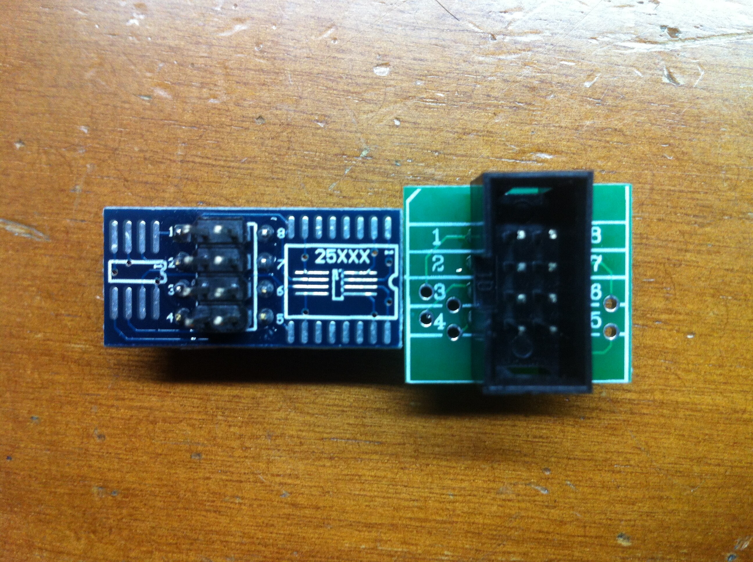
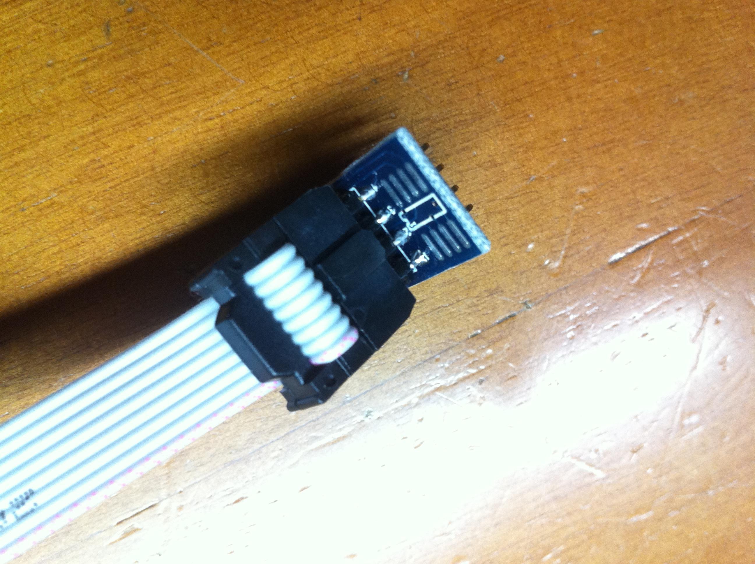
2. Connect the programmer to your flash chip. If your chip is in DIP-case (i.e. you have desktop motherboard with socketed BIOS chip), just gently plug it out, insert into programmer’s ZIF-socket and press the lever to fix it in position. If your chip is in SOIC-case, you can use the supplied converter board, SOIC test clip, another ZIF-socket or just solder a tiny wires onto chip’s pins. You can also try in-system programming (i.e. programming the chip without desoldering it) but it can easily fail because the programmer needs to provide power for the half of the motherboard that way, and results of such tries are not predictable. Sometimes it works, sometimes it’s not, it’s for you to decide.
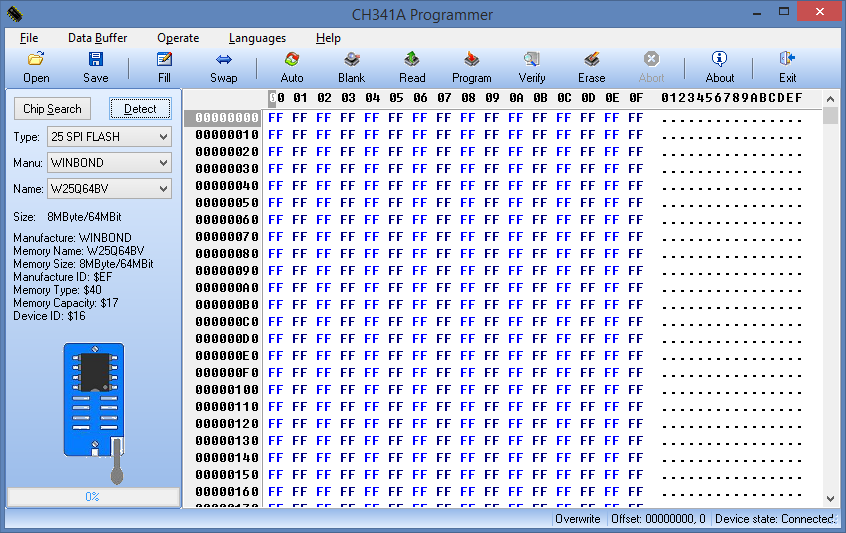
3. Connect the programmer to USB port and run the software. Select 25 SPI Flash as Type and press Detect button, your chip should be detected.

01.png


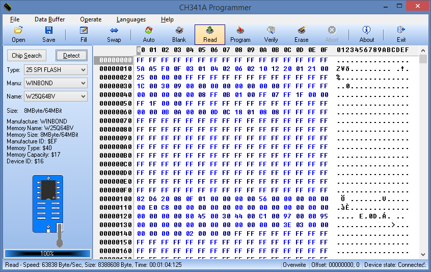
4. Press Read and wait for the operation to complete. Press Save and save your chip contents as backup somewhere.

02.png


5. Press Open and select the image you want to flash. Press Erase to erase chip contents, it’s very fast on most chips. Press Program and wait for the operation to complete.

03.png


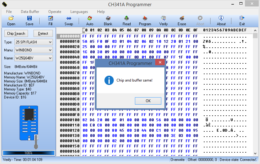
6. Press Verify and wait for the operation to complete. If the chip is OK, verification will be successful, if not - check your connections, try to erase the chip first and repeat the whole process.

04.png


7. Disconnect the programmer from USB, return the SPI flash chip to it’s original place and try to boot the PC. If your image was OK, the system should work now.

EDIT by Fernando: Insecure eBay link replaced by a secure one

CH341A Programmer.zip (854 KB)

CH341A_FLASH_programm_v1.29.rar (3.5 MB)

2 Likes

Hello what you think about Gzut dream pro 2 i have it but i was unsucsess to flash empty chip on asus maximus hero VII
Its program correct chip but its not boot up UFB flashes it also but pc not post possible its not like type of my chip.
I ask is anyone got empty chps flashing work on Z97 mobos.

It’s OK too, even faster, but not as cheap as CH341A-based ones.
I have also seen that Z97 boards have problems working with non-factory flash chips, but I don’t know the reason of it. All of modern SPI chips has a page of write-once memory to write some vendor data, which can then be read by a special SPI command, but I don’t have such system to test and find out, so I simply don’t know.

@CodeRush

Hello Coderush, yesterday my SPI chip got bricked because FWUpdLcl decided to get stuck at 50% for some weird reason. So the ME is bricked and I have to reflash the whole SPI chip now. It’s a laptop and of course the chip is soldered. A question, is it possible to revive it without any unsoldering, meaning while the chip is still on-board? I was thinking to get some programmer because I also wanted to flash another working desktop SPI that has a locked descriptor.

The bricked laptop chip is MX25L3206E (4MB) and the other desktop chip is MX25L1605A (2MB). It’s mainly important to get the laptop working again (MX25L3206E). Datasheets attached, do you think it’s possible?

500020029_580.jpg

MX25L1605A SPI Flash.pdf (966 KB)

MX25L3206E SPI Flash.pdf (2.46 MB)

Yes, but you will require an external power supply to power chip’s 3.3V voltage rail and a SOIC clip to connect to it.

Thank for the answer @CodeRush . I have searched around but I admit I don’t understand most of what I’m reading relating to programmers and chip types.

The 3.3V aren’t supplied by the USB interface? If it is not, how can I provide power to the chip, meaning: what am I looking for exactly? A picture would help to narrow it down.

Also, looking at the CH341A cheap programmer you showcased, I saw that there are some SOIC clip differences. Once more, what am I looking for?


I suppose this is what I am trying to do. If the system is powered-up (but of course doesn’t boot), is a separate power source for the chip required?

3.3V is definitely supplied by USB interface, but it’s only about 100 mA current possible for cheap programmers because of cheap components. It’s more then enough for SPI chip along, but can be not enough to power the half of a board during ISP.
If the system is powered up, you don’t need any other power supply - system’s suply is enough.
You need SOIC 8 pin 1,27mm pitch test clip, like this one.

Unfortunately the CH341A you posted (cheapest) is for Germany only. Since items from China might take a month to arrive, I am mostly looking for something in EU so that it won’t arrive after a month.

I have narrowed it down to these choices: 2 CH341A programmers and 1 SOIC8 test clip.

CH341A: https://www.ebay.co.uk/itm/CH341A-24-25-…=item23489b6e23
CH341A: https://www.ebay.co.uk/itm/24-25-Series-…=item5d540aa2d6
SOIC8: https://www.ebay.co.uk/itm/SOIC8-SOP8-Fl…=item418c8cb269

First of all, there are compatible, right? I think the SOIC8 clip is fine (also includes the little converter board). Regarding the two programmers, I don’t think they are different except a slight price difference.

Also, the CH341A you posted and the above are only for 8-pin chips, right? They have two 8-pin sockets but I’m not sure, are these for programming 2 x 8-pin chips at once or can they also accept one 16-pin chip? Both chips I want to flash are 8-pin but I’m asking for future reference.

EDIT by Fernando: Insecure eBay links replaced by secure ones

Yes, they are all compatible and based on the same reference desing.
The socket is for 2 8-pin DIP-300 packaged chips, one part is for 24x series (I2C interface), another is for 25x series (SPI interface).
Some programmers also have a pin header with SPI signals (Power, Ground, CS, CLK, MOSI and MISO), so you can connect it to 16-pin chips using jumper wires, but the socked is for 8-pin ones.

Ok, I’m almost ready to order. The 2nd one seem to have a picture with pinout:

http://i.ebayimg.com/00/s/MzM4WDUwNg==/z…FUs43F/$_12.JPG

But I don’t think it’s what you mentioned. Either way, I would need a SOIC16 clip for that which I don’t need to buy right now.

The first one has a led too. Unless the 2nd one can be used for 16-pin (highly doubt it), I’ll order the 1st one + SOIC8 clip.

The SOIC8 clip ebay listing also has a “10 PCs PCB Convertor” but this is useless for me if I understand properly.

is it possible to flash chip while system is turned on(windows running???)?

i’m trying to flash bios on my chip Winbond w25q64fv but once i connect cable to chip i get device status: not connected (chip soldered to motherboard)

Could it be because of not enough power power from programmer? or do you think it can be anything else? (i tried on win 8.1 64bit and win 7 32bit)
you think i’ll run into any trouble because the chip is w25q64FV and the software supports w25q64BV

@CodeRush

So, the CH341A + SOIC clip arrived. The desktop was flashed easily by putting the chip directly at the programmer. The laptop is not really working though.

This is the actual programmer:

IMG_0186 - Copy.JPG


With the clip, came two boards:

IMG_0187 - Copy.JPG


I am not sure which I’m supposed to use but I tried both of them at my tests.

I connected the cable to the board like this:

IMG_0188 - Copy.JPG


Then to the programmer like this:

IMG_0189 - Copy.JPG


Then I connect the clip to the laptop BIOS chip. If the laptop power cable is connected and the procedure above was done correctly, the programmer is detected in Windows. But the chip is not detected as it should and when reading it returns FF. Programming always fails because of that. If I power the laptop on (stays on but at black screen) and then I connect the clip, the laptop powers down. Sometimes it might not power down when connecting the clip but trying to detect or read the chip will surely lead to that.

Am I doing something wrong?

I was afraid of that too. Now you need to desolder the chip, there is nothing you can do without desoldering.


What about external power for the chip? So that the laptop’s power is off completely. If it’s doable, what would I be looking for?

The main problem by ISP is not the main power, but data lines power, which is normally not enough if driven from cheap non-ISP-ready programmer. You can try to desolder just the power line and use the power from the SOIC clip, but it will be much better to desolder the whole chip, which can be done using a hot air station or just a normal soldering iron combined with solder wick.

Hello CodeRush. Bricking my Asus G73JH as many before me has lead to this forum. Im now looking into this cheap programmer(CH341A), but i cannot download the software/man you’ve attached. Both chrome and IE says its protecting me from malware or somthing along those lines. Is there another way to share this?(i’ve tried other sites aswell, all leads to malware protection…)

I am currently unsuccessful reading my winbond w25q32bv chip using a rashberry pi and flashrom. I belive that flashrom should support my chips series, so i’ve ordered 3 new aftermarket chips of same model.
I’ve connected all the pins, including /wp and /hold which gets 3.3v.
Do you think getting one of these would be better than using flashrom/rpi?

Cheers

Recompressed with 7z - now nothing should complain about Malware - except it indeed is Malware :wink:

1
 
http://www.datafilehost.com/d/d2418983
 

Use download button on below left, not at the top!

That worked, guess everything in chinese is treated as spyware nowadays. The programmer supports my chip(w25q32bv) and i got a rom ready. However, its got those flat connectors. Ive already tried soldering wires onto those once and its a pain to say the least. How does the 25spi converter work exactly? it seems to me i have to solder it to the converter board… its hell getting it off once all 8 legs are soldered in place. any thoughts?

I made video also sucsess managed todo it on M7H on Z97 its helps possible someone who first time on trouble.

Hi,

I bought an CH341A off of Amazon along with a blank Winbond W25Q64BV and transferred my bios serial and mac info using f4editor onto a fresh bios ver 3603 for the Asus P8z68 Deluxe Gen1 board. I then plugged the bios chip into the socket of the CH341A just like in the illustration on the CH341A programmer tool and was able to verify chip type and erase chip, load image then program the chip BUT Verify fails and says contents don’t match. I could even backup the burned image onto a file and read it correctly using the f4editor. Think this chip is safe to use?

Note: My original bios chip is in perfect condition still in the motherboard. Just trying to learn how to flash these things for fun. Got to say though first time I inserted chip into sp341a backwards on wrong end. Possible chip is burned?

Thanks.

@coderush Do you think cause the bios chip was blank there’s some regions not getting flashed? I used hex edit to do a file compare on the original bios file pre-burn and after-burn and certain parts did not match. Thanks again!