Broke server. Need help!

edited to state the correct mainboard model name.

To put things into perspective, this is an old server, ancient in fact, and it is not in production use anymore but it bugs me because I never broke things to a point where I could not easily fix it myself. Until now. But this time, I really need help. There’s a story behind what happened, which I will include at the bottom, but the why doesn’t matter.

I need help with

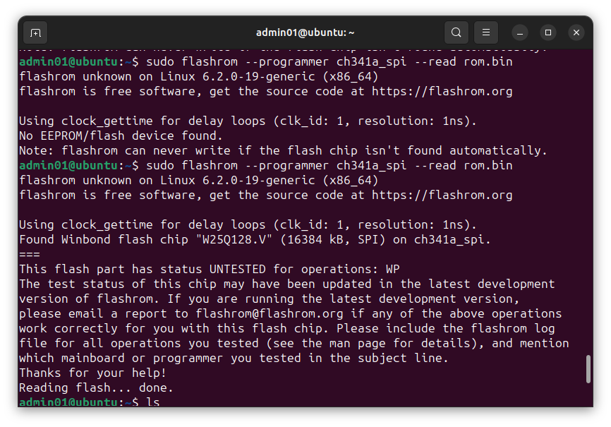
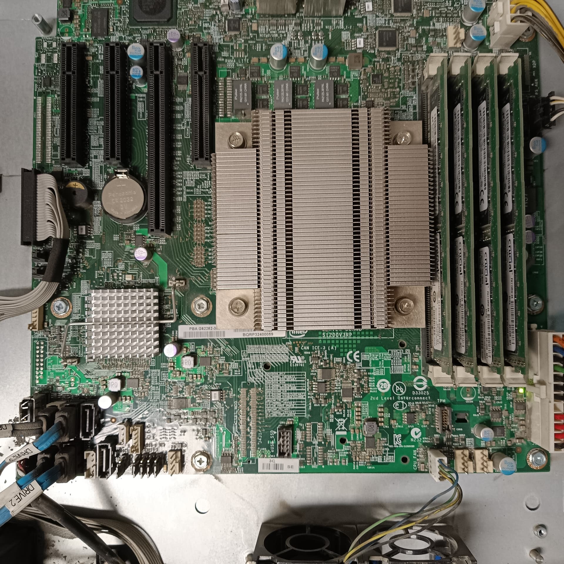
  • identifying the flash chip

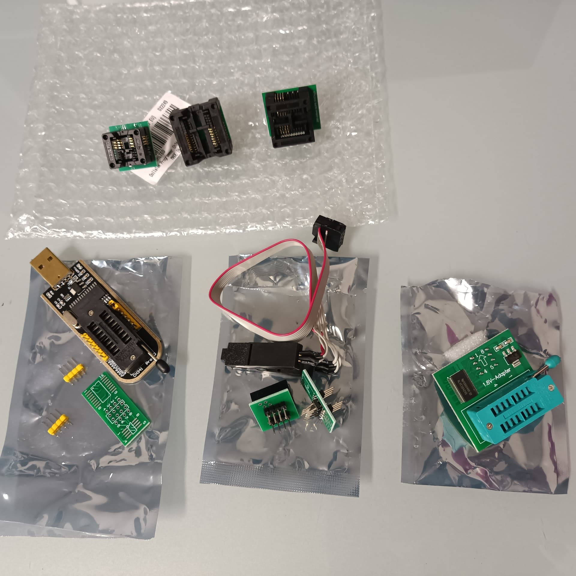
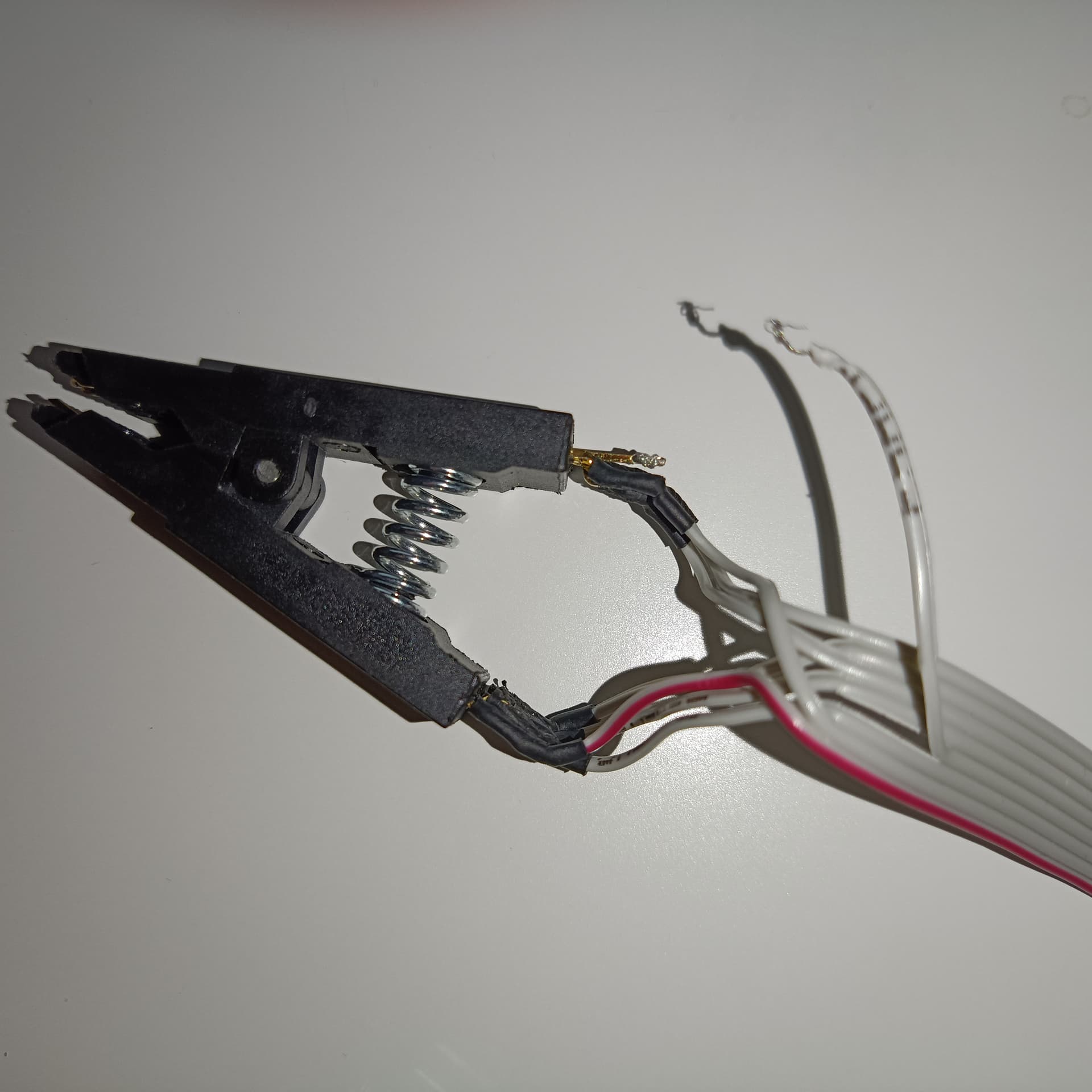
  • advice on which flash programmer I need

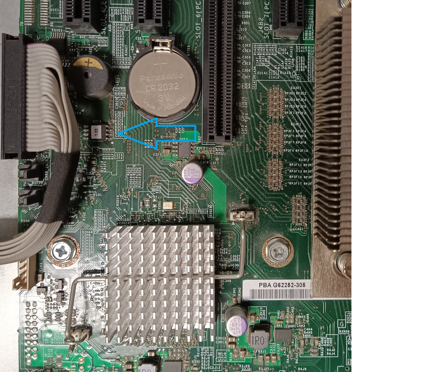
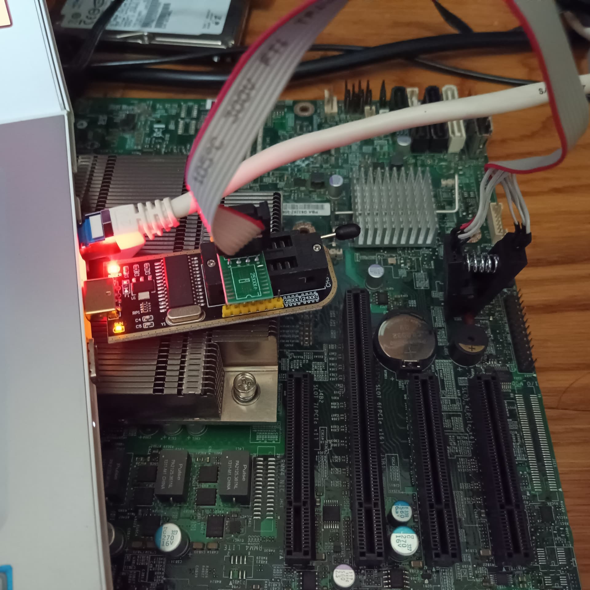
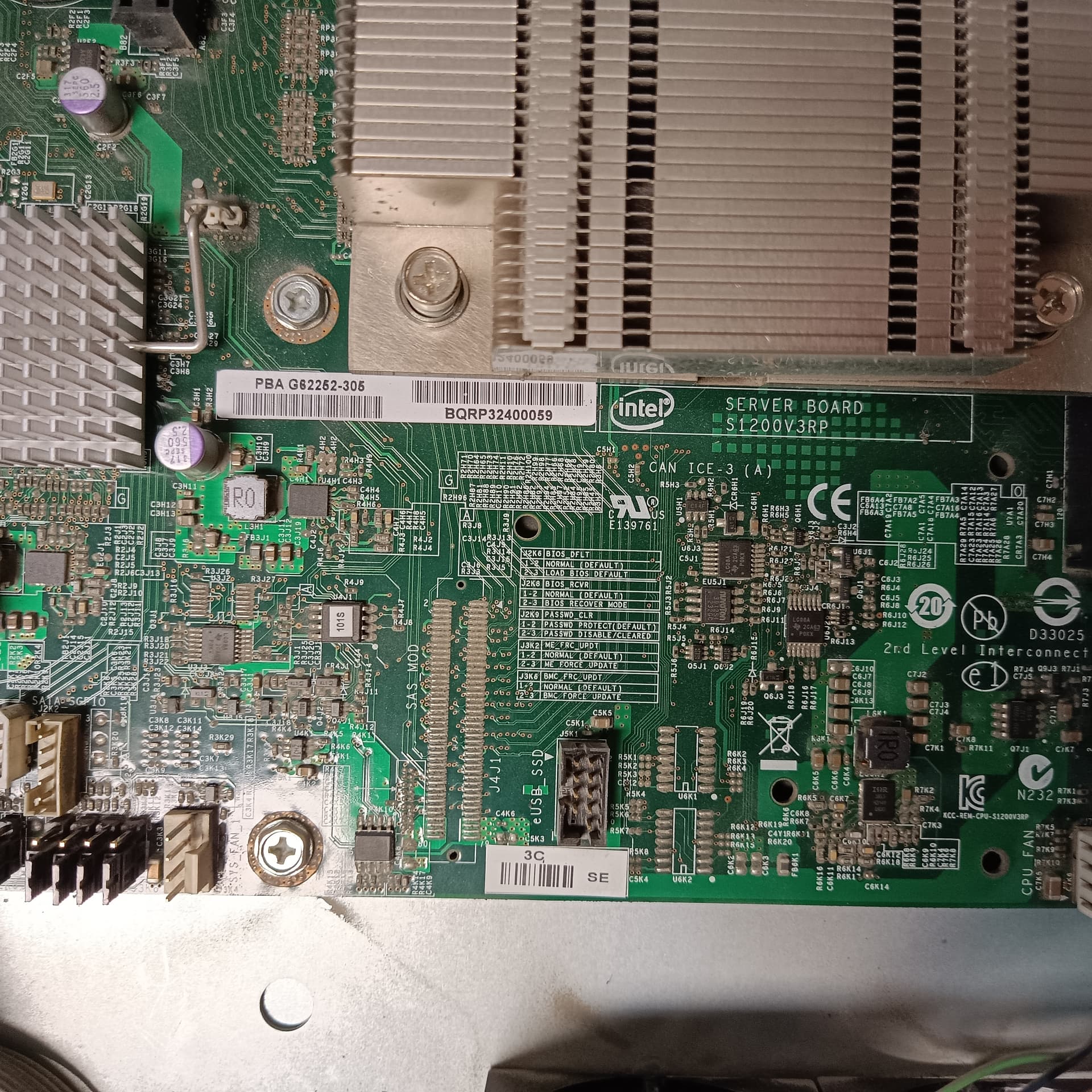
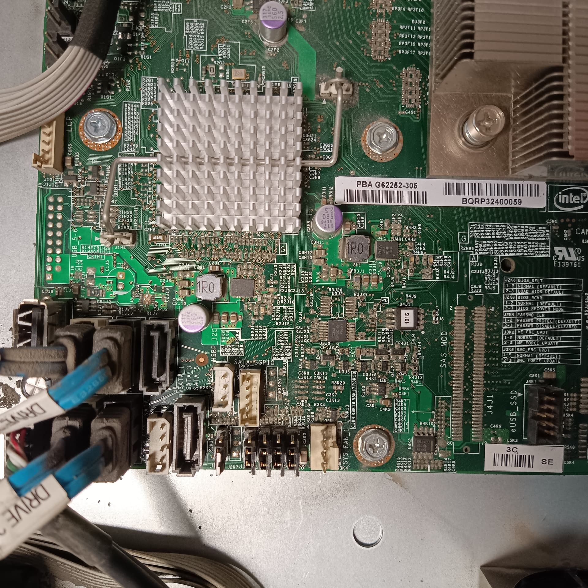
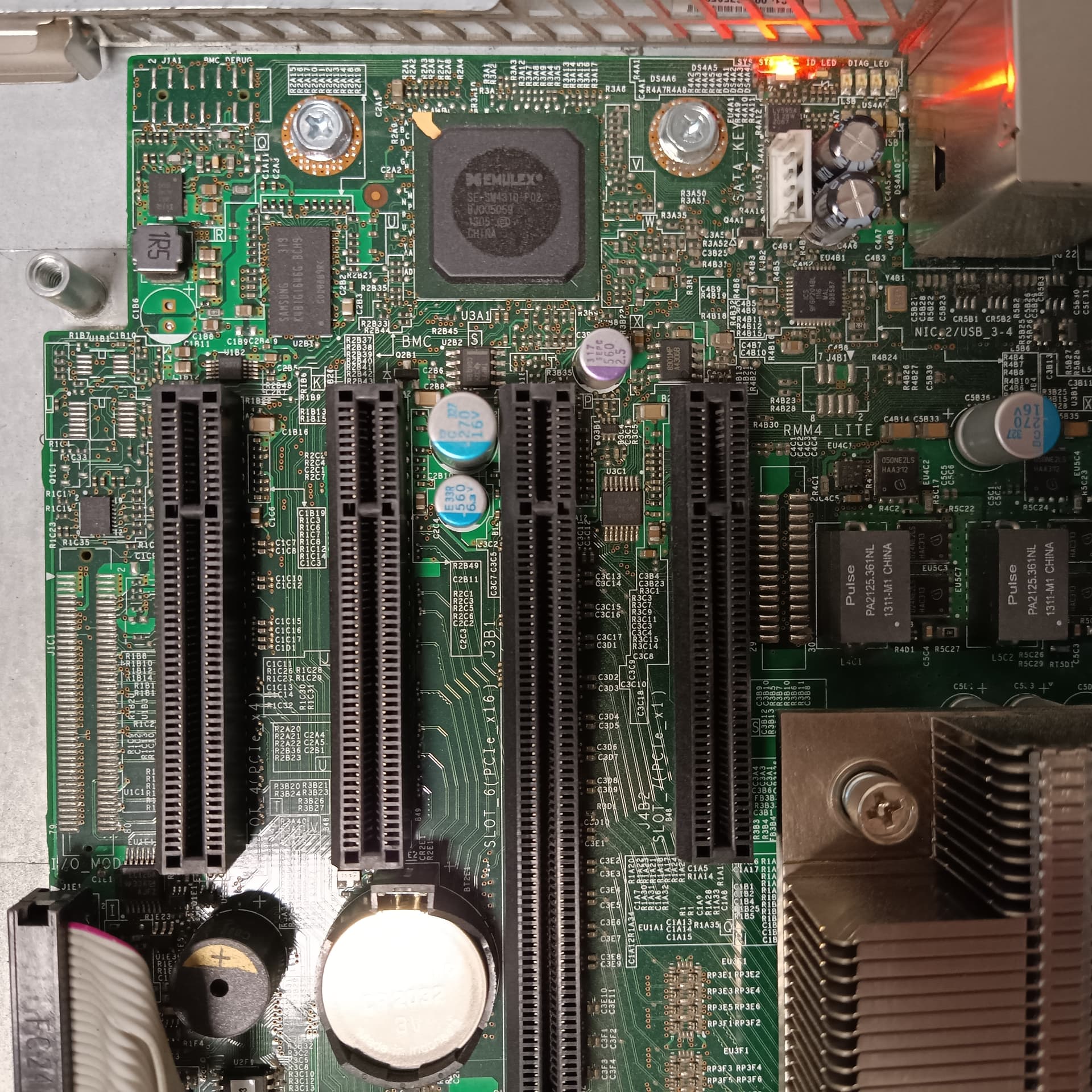
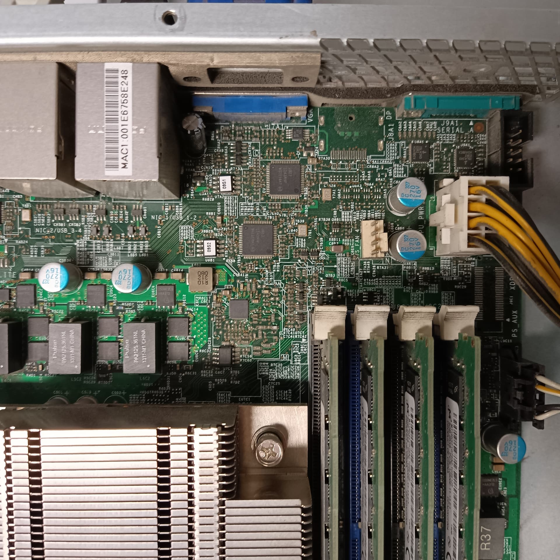
Here are pics of the board. Maybe you can spot the flash chip? The board is Intel S1200V3RPS. Sorry for the dust. I should have used dust spray first.

Pics


A little background of what happend:

So, what happened? (tldr)

The board is Intel S1200V3RPS. I flashed the wrong BIOS. I flashed a BIOS for S1200RP family boards and the description listed a few S1200RP boards but not the S1200RPS. Later, when I found out that there was a problem, I dug deeper and in the Intel docs, I found something to the effect “Do not use this BIOS on S1200RPS boards”. Oh well.

At first, it didn’t seem there was a big problem. The only thing I noticed, was that the backup BIOS did not automatically update. On these boards, when the board posts successfully after a BIOS update, the active BIOS is copied over the backup BIOS. That didn’t happen. I don’t know this for sure, but I assume that the board booted from the backup BIOS. Otherwise, nothing seemed wrong to me.

At that point, I decided to flash the working, proper BIOS but that didn’t work. This was probably because the BIOS version of the proper BIOS is lower than the version of the bad BIOS. I figured I needed to set the BIOS update jumper to force a BIOS downgrade and made a note to do this when I had physical access to the server (So far, I had done everything remotely using the servers BMC with KVMoverIP). Everything still seemed mostly fine because the operating system booted, and the server was working.

A couple of months later, we had a power outage and the server wasn’t on UPS. This turned out to be significant, as this was the first time the server was completely without power since I had flashed the bad BIOS. Since the outage, the BMC hasn’t worked. The BMC website is offline. Ping doesn’t work, etc. Despite that, the OS was booting, things were fine otherwise.

Yet another couple of months later, I tried to fix this by accessing the server physically and setting the BIOS downgrade jumper and, oh my!

I noticed that all of the server’s fans were spinning at insane speeds. The sound was deafening! It seemed like it was ten times louder than any other server in the rack.

Just as I had suspected, setting the BIOS jumper allowed me to downgrade the BIOS to a proper BIOS version for this board. I did the same for the BMC (setting the BMC jumper, downgraded to proper BMC version). To my surprise, the BMC still did not work.

Turns out the culprit is the ME firmware. It is corrupted which is why the fans spin like crazy. It also seems to be the reason, the BMC doesn’t work.

I tried to fix ME firmware by setting the “Update ME” jumper, but it didn’t work! I can’t flash ME fw because ME fw is broken. A catch 22!

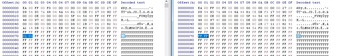
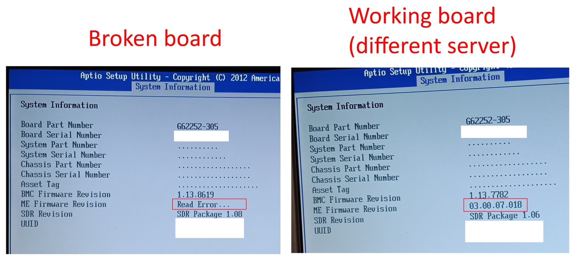
Here, you can see, ME fw version shows a read error. For comparison, a different, working server with the same board, next to it.

When I set the “Force ME update” jumper, it hangs at this screen:

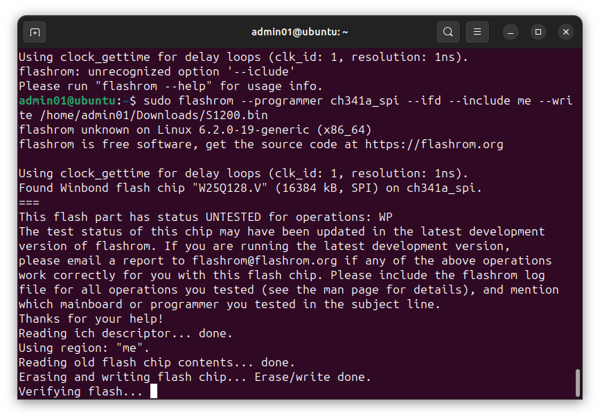
When I do not set set the jumper and try to flash ME region, I get:

Failed to lock/unlock ME Flash.

I also read in some Intel docs, when setting the Force ME update jumper does not work, try to set the Force BMC update jumper.

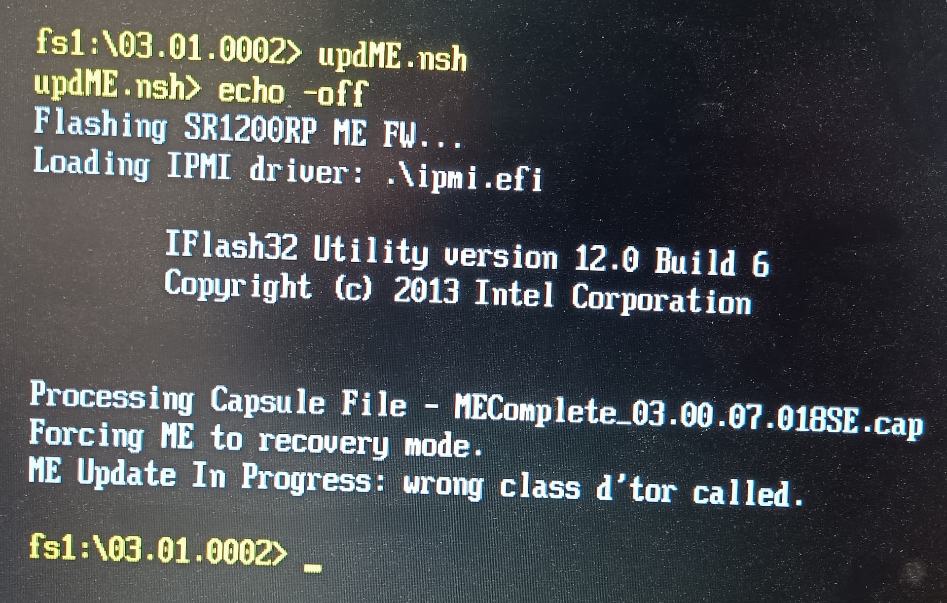
When I set the Force BMC update jumper by itself, or if I set the force BMC update jumper and the Force ME update jumper, the board does boot, but I get this:

wrong class d’tor called

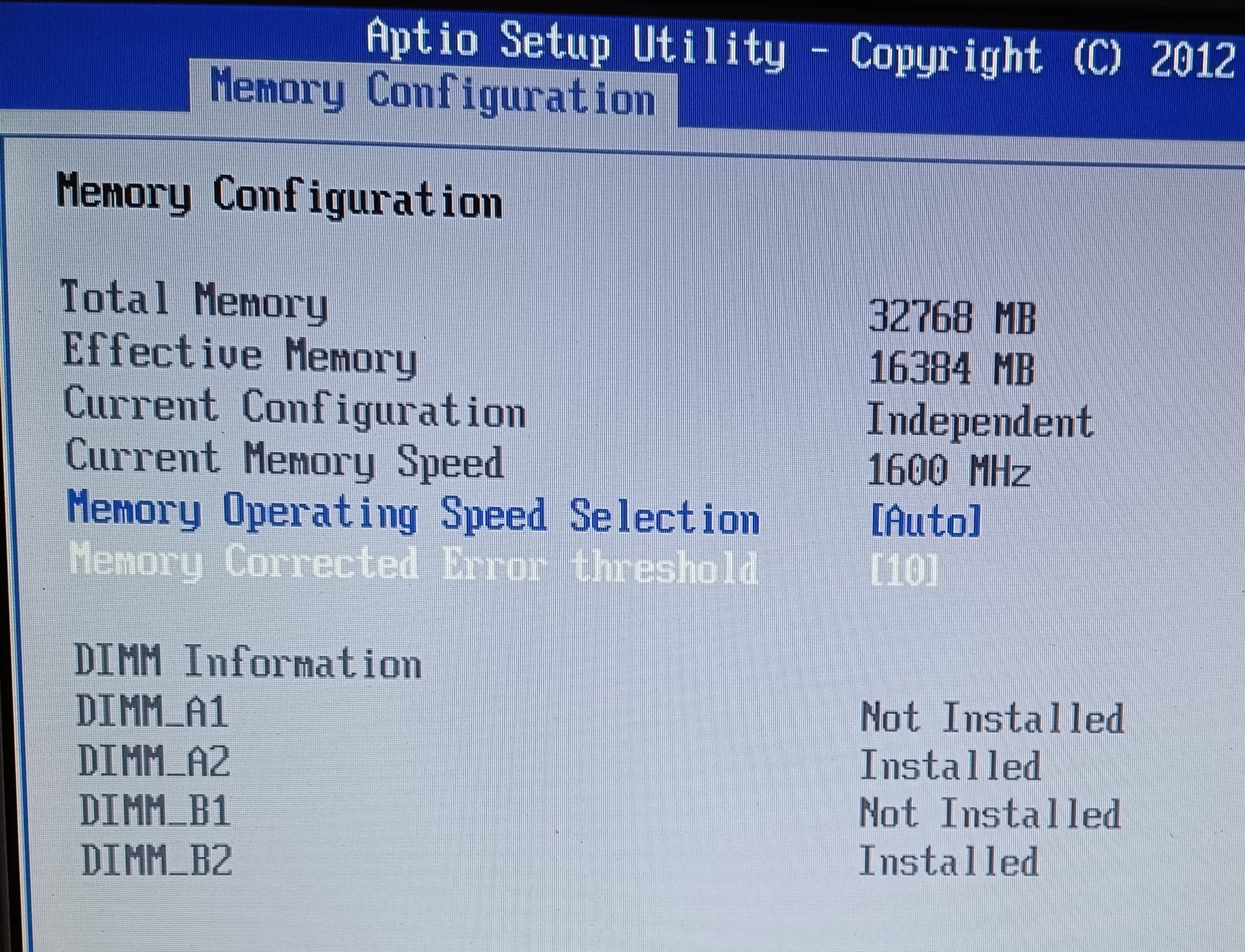
Another thing that I noticed, even though the board recognizes 32 GB memory, it only uses 16 GB now. It only uses 2 out of 4 memory slots but all 4 slots are occupied.

What sort of chip is the one with the sticker saying ‘101S’ ?

And another one with 1.03 on it (U2F1)?

Chip numbers are iedntical to the ones mentionend here:

Only place with a dump I could find:

But that’s paid and I don’t know if there’s really 2 chips, second one may be

You’d need a CH341 programmer and a SOIC clip, I don’t think they used 1.8V chips this early, so possibly no adapter.

Might be possible that the update files don’t have the correct structure simply to be flashed, ME looks good, but unsure for bios region, seems they update single EFI volumes- volume with volume top file is one of the first but should be last.
In any case you’d need parts of your original bios, FD and GbE, meaning you shoud have a 100% good dumps of the existing content before overwriting something.

1 Like

It didn’t even occur to me that I need to know not only where the flash chip is, but what model it is. Do I need to know the model before I get the programmer, or does that not matter?

The manual of the S1200V3RPS does not help. It offers no information on this whatsoever. But I just found a few things in some manuals for other boards.

  • It seems “U2F1” (sticker “1.03”) is the BMC FW flash ROM.
  • “U6B1” (sticker “09S2”) seems to be the BIOS chip, probably also contains ME firmware.
  • On the chip close to it, that looks identical, “U7A2” (sticker 09S1), I was unable to find anything (backup BIOS chip?).
  • As for “U4J1” (sticker 101S), I did not find anything but it is mentioned in the link you gave (U4J1-25Q128.BIN). Maybe this is the real BIOS or backup BIOS?
  • Then there is the other file from the: U2F1-25Q128.BIN. I cannot even find “U2F1” on the board. “25Q128” may refer to any number of different flash chips.

Either way, it seems this is going to be more complicated than I thought. There might be 2 or 3 flash ROM chips on the mainboard. BMC FW, BIOS, and possibly backup BIOS might be on a separate chip.

I don’t know what’s under the stickers.

There is an identical server that works, from which I can get a ROM image, though thanks for the warning about the MAC address and such things.

The BIOS update does not come as one file. It looks this:
BMC_i_0113r7782.bin (10,7 MB)
MEComplete_03.00.07.018.cap (3,81 MB)
MEComplete_03.00.07.018SE.cap (3,81 MB)
R03.01.0002.cap (4,69 MB)
R03.01.0002Rec.cap (4,94 MB)

On top of everything, the NICs seem to have their own flash chip as seen in the manual I posted. So, dealing with 3-5 flash chips?

Normally the chip type (You’re supposed to remove the stickers!)
.

U2F1:

Version number like FRU but too large a chip for only FRU?

09S1 and 09S2 seems network related. Nothing in the update that seems to be related to NIC firmware so far.

Find the chip types, buy a corresponding programmer, most probably a normal ch341 with SOIC 8 clip will do.

Read the chips carefully, you need a 100% valid dumps.

Let’s then have a look into the dumps and into the update files to find out which parts aren’t corresponding to your model!

  • Do you have a link to the wrongly fashed firmware?

  • What firmware version was the server on before flashing with the wrong firmware?

1 Like

I flashed this one (03.04.0006):
Intel® Server Board S1200V3RPL/S1200V3RPO/S1200V3RPM Firmware Update Package for EFI
Literally reads

Important note: Do not use this package on the Intel® Server Board S1200V3RPS or Intel® Server System R1304RPSSFBN.

You’d think there’s a failsafe in place that prevents flashing the BIOS meant for a different system, but no, there isn’t. Anyway, I blame myself really. :slight_smile:

Before that, it had “03.01.0002” (S1200RPS_EFI_BIOS03010002_BMC113_FRUSDR108.zip). It seems Intel pulled all BIOS update downloads for this board, probably a contributing factor in why I flashed the wrong BIOS. I cannot find it on their website but I can provide the files if this helps.

Btw, thanks so much for helping me @lfb6 !!

edit: I will remove all the stickers and take more pics but it’ll be when I have access to the server.

edit2: To be clear: I only read “Do not use this package on the Intel® Server Board S1200V3RPS” after I had already done it.

edit3: This is unrelated but, I can see now, by looking at the server’s manual that the fan was installed incorrectly so that it blocks air flow. :scream:

Wasn’t thinking or guessing at all, tried simply to understand what happened in the firmware.

For example:
The bios region has 5 of 9 efi volumes identical, but volume for PEI and the volume with the DXE drivers are significantly different.

The ME region is present in 2 differently configured forms in the ‘wrong’ bios (MEComplete_03.00.07.024SE.cap and MEComplete_03.00.07.024.cap) and in one form in the correct bios (MEComplete_03.00.07.024SE.cap). Interestingly enough the MEComplete_03.00.07.024SE.cap files have identical ME regions. Wasn’t able to determine when which version get’s flashed from the scripts.
Did you use one of the scripts- startupse.nsh or startup.nsh? If yes: Which of the two scripts?

It’ll be interesting what your dumps will show. You might try to dump the regions with fpt from ME 9 ME- tools package, owned a Asus C222 board where parts could be dumped (but the tool worked just once after a reboot).

1 Like

I used startup.nsh. What is startupse.nsh? What is the difference between
MEComplete…SE.cap and MEComplete…cap? I cannot find an explanation for this.

Different ME configuration, FITc for (Denlow-) SPS is hard to find, so difficult to check. Only difference for the 2 mentioned scripts is flashing different ME.

1 Like

Just wanted to post a quick update: Thanks for the tip to use CSME tools version 9! This worked (Intel ME System Tools v9.5 r6)! I had previously tried different versions and none of them worked.

Remotely, (as I do not have physical access right now), I have been able to get this from the working server:

.\fptw64.exe -I

Intel (R) Flash Programming Tool. Version:  9.5.40.1868
Copyright (c) 2007 - 2014, Intel Corporation. All rights reserved.

Platform: Intel(R) Server Essential
Reading HSFSTS register... Flash Descriptor: Valid

    --- Flash Devices Found ---
    W25Q128BV    ID:0xEF4018    Size: 16384KB (131072Kb)

    --- Flash Image Information --
    Signature: VALID
    Number of Flash Components: 1
        Component 1 - 16384KB (131072Kb)
    Regions:
        Descriptor - Base: 0x000000, Limit: 0x00FFFF
        BIOS       - Base: 0x400000, Limit: 0xFFFFFF
        ME         - Base: 0x030000, Limit: 0x3FFFFF
        GbE        - Base: 0x010000, Limit: 0x01FFFF
        PDR        - Base: 0x020000, Limit: 0x02FFFF
    Master Region Access:
        CPU/BIOS - ID: 0x0000, Read: 0x1B, Write: 0x0B
        ME       - ID: 0x0000, Read: 0x05, Write: 0x04
        GbE      - ID: 0x0118, Read: 0x09, Write: 0x08
 Based on the Host Region FRACC the Host/CPU/BIOS has ( 0x00004B5B ) :
             Read    Write
    Desc  :  Yes     Yes
    Host  :  Yes     Yes
    ME    :   No      No
    GbE   :  Yes     Yes
    PDR   :  Yes      No

Total Accessable SPI Memory: 16384KB, Total Installed SPI Memory : 16384KB

FPT Operation Passed

Further, as you can imagine from the above output, I was unable get a complete dump because read access to the ME region is blocked. I have been able to dump the other regions individually:

BIOS.rom
DESC.rom
GBE.rom
PDR.rom

edit: no idea how to dump BMC ROM but i don’t think that matters. Only the BIOS/ME seems to matter.

dumps.zip (4.4 MB)

    --- Flash Devices Found ---
    W25Q128BV    ID:0xEF4018    Size: 16384KB (131072Kb)

Is the above info enough to tell us what programmer I need to get?

Documentation - Winbond

Now many SPI apps have the W25Q128BV on their database, some apps will work better others fail, all depending on the motherboard, so get on it.

[GUIDE] The Beginners Guide to Using a CH341A SPI Programmer/Flasher (With Pictures!) - BIOS/UEFI Modding / BIOS Modding Guides and Problems - Win-Raid Forum (level1techs.com)

[GUIDE] Flash BIOS with CH341A programmer - BIOS/UEFI Modding / BIOS Modding Guides and Problems - Win-Raid Forum (level1techs.com)

[Guide] Using CH341A-based programmer to flash SPI EEPROM - BIOS/UEFI Modding / BIOS Modding Guides and Problems - Win-Raid Forum (level1techs.com)

Depending on the board, CMOS battery off (some ON), PSU standby off (some ON).

1 Like

A simple CH341 programmer should do, there might of course be difficulties with this specific board, but for this chip it’s completely OK:

https://www.amazon.com/ch341a-programmer/s?k=ch341a+programmer

Since the ME region can be replaced from the update file this should give us a complete bios image.

So far nothing seems to have happened to the bios region, no stuff from the ‘wrong’ update found here…

Volumes in bios region (backup bios does mean that there two sets of bios volumes in this region):

1 = = NVRAM
2 = = empty
3 = 11 = 9 in update (both versions)
4 = = 8 in update (OK version)
5 = = 7 in update (both versions)
6 = = empty
7 = = almost empty
8 = = 6 in update (both versions)
9 = = almost empty
10 = 12 = 4 in update (OK vers)
11= 3 = 9 in update (both versions)
12 = 10 = 4 in update (OK version)
13 = 15 = 3 in update (OK version)
14 = 16 = 2 in update (OK version, 2 minor diffs)
15 = 13 = 3 in update (OK version)
16 = 14 = 2 in update (OK version, 2 minor diffs)


The differences in volume 14 = 16 in bios region to volume 2 in update:

There’s one glitch in NVRAM, the space between last entry and GUID store should be empty, but there’s a non referenced GUID there.

So firste step would be to just replace ME and try. If- against all odds- your dump shows the correct ME for your system, it’ll get a little harder to explain what might’ve happened…

That would be the file, it’s just composed with the parts you dumped pluss ME region from update:
S1200.zip (5.3 MB)

1 Like

Thank you! I ordered the programmer and I should have it in a couple of days. I will see if can make a dump of the flash ROM.

If that works, should I try to flash the ROM image you made? What about MAC addresses? If I write only the ME region, will that overwrite the MAC addresses?

Please do a dump with the probgrammer first and compare it to the parts you dumped with fpt since the this fpt version is originally made for another ME platform. Compare the resulting file in a hex editor with the partial dumps you made, they’re just copied after each one- desc, gbe, pdr, me, bios region.

Mac and other machine specific data- there’s no mac in gbe, just a dummy, but server boards do have the macs often stored in NIC firmware. Otherwise there’s no machine specific data in ME region and the rest of the firmware would be as much ‘original’ as possible.

1 Like

I have been told that the programmer has been delivered and I am making my way to the server now. I will try to make a dump first.
The thing I don’t fully understand yet is: Should the server be unplugged, or on AC but powered off? Or powered on?

Don’t try to write if you can’t/couldn’t read!!

Try without power

I received these parts in the mail.

For the most part, I can’t seem to make a connection between the part that connects to the SPI chip and the chip itself. Mostly, the clip that physically connects to the chip does not stay on and if it does, no connection is made. It looks like, I need to look at more guides.

I have probably tried 50 or 100 times and I was only able to make a connection once per chip.

Here is my setup. I removed the board from the chassis and took it home with me.

The chip that was labelled “1.03” (the chip that is close to the CMOS battery) is either the BMC (no BIOS, ME region?) or I did not get a valid read at all. UEFI Tool reports that there is no ‘top file volume’ in the dump.

The other chip , labelled “101S” seems to be the BIOS/ME chip. When I had a connection to that chip, I tried to make a dump, then tried to flash ME region (using S1200.zip from above), and then tried to read again.

commands I used
to dump:

sudo flashrom --programmer ch341a_spi --read rom.bin

to write ME region:

sudo flashrom --programmer ch341a_spi --ifd --include me --write S1200.bin

What I noticed:

  • Flashing ME region didn’t seem to fix the issues. Though, I believe I could see in the before/after dumps that ME version changed from x.x.x.18 to x.x.x.24.
  • The issue with ME version showing “Read error” in conjunction with only 16 GB of 32 GB RAM being used seems to have fixed itself (before I did anything with the programmer). Perhaps this happens only when the ‘flash ME’ jumper is set?
  • When I did get a connection, I had AC plugged in and flash ME jumper set to enabled. When the power cable was unplugged, I did not get a connection. Then again, I only got a connection once, so who knows.
  • I think I made the mistake of forgetting to remove the battery. I will try again without it.

I will try again today.

dumps.zip

Yes, that puts ME in recovery mode and it doesn’t function as expected.

If your ME was 3.0.7.18 now before flashing then it never got updated when you tried with the ‘wrong’ update. You possibly didn’t do anything to your ME firmware and bios and trying the update was thought to be the culprit even if it did happen long time ago.

So all this boils down to your BMC not working, the rest seems to be OK? Fans spinning might as well be caused by BMC not controlling them. The rest of symptoms seems related to having had the ME jumper set.

The dumps look otherwise fine and are valid- the bios region is identical except for NVRAM, but that’s normal. And yes, positioning the clamp can be a pain but after some time one gets used to the proper way…

No idea regarding BMC firmware- and it’s not at all clear that this is even BMC firmware related, maybe it just died.
How did you manage to downgrade(?) the BMC firmware without BMC working?

1 Like

The BMC firmware never gave me any issues when trying to flash it. That’s why I didn’t suspect it as the problem but I believe you are correct. Perhaps ME is not the issue. After all, BMC is not working (no ping, BMC website offline).

I can update the BMC firmware (or write the same version again) using Intel’s provided tools (startup.nsh, etc.) and I can downgrade it that way too, if the force BMC update jumper is set.

It seems to me that both ME and BMC have the potential to continue to run and function even if a wrong version is flashed until such a time that the system is completely without power.

Yes. possibly it is not related to flashing firmware. I don’t know at this point.

My SOP8 clip just broke :frowning:

Im not surprise at all with that… happened to me long time ago when i did the same and bought a cheap “big pack with possible accessories offer” like yours… money speaks here and its not a product for mean or long term uses.
The market “offers” what it is plain and simple… users tend to ignore and look to their “pockets”… normal, the “Asian” market knows this… The device itself is “reliable”… never had a failure so far but the connection itself, is as you already noticed.

1 Like

Meanwhile, I got another programmer kit and this time, the clip is working well. I practiced a little bit today with a mainboard I have at home and now I can make the connection work usually the second time I try.

But the second kit has the connector clip pins completely crocked.

It seems to me the quality of the flash programmer is good in these kits but the cables and clips are of bad quality. I ended up creating one working kit out of two purchased kits.