Caswell CAR-2051 (SPI Flash) - BIOS admin password

Greetings everyone,

a newcomer on Win-Raid forum, though far from being a stranger … been following forum posts on and off for quite a while.

DISCLAIMER: I do apologize in advance, if I failed to post in appropriate forum section. Also, be merciful if you find any improper use of the term “BIOS” in the given context, or any incorrect references to AMI BIOS platform/family and version.

So here’s the challenge that inspired my post - a couple of months ago I got an Atom C2000 platform networking appliance - Lancom R&S UF300 (a.k.a Gateprotect GPA-300v2), essentially a custom modified Caswell CAR-2051 with CAPB-2051 board and Atom C2558 CPU. Bare metal Caswell CAR-2051 appliances seldom show up on the second hand market, for not being designated for consumer market. There’s absolutely no documentation for this EOL device available on Caswell’s website, nor any downloads for BIOS updates, Intel AVR54 Bug status updates, no drivers, nothing. Try Googling “CAR-2051”, you’ll get something like 3-4 relevant hits at best.

A device was preloaded with Lancom R&S UTM software (expired license), so I opted to install a serial image of pfSense (no VGA on this one, just RJ45 Console port), by taking out SSD and installing pfSense, having SSD hooked to the board in my desktop PC. The pfSense install was successful, works without a hitch on CAR-2051. Still, I wasn’t happy about the fact that I couldn’t access the BIOS settings - the default “TAB” key for serial console BIOS Setup access didn’t work, which meant that serial port console redirection must have been disabled in BIOS. That’s a customized setting, commissioned by Lancom R&S, as the CAR-2051 User Manual implies that it should be “Enabled” by default. Just to be clear - I was getting the console output (running minicom terminal emulator on laptop), but only after OS bootloader would take over the boot process. So I hooked the console cable to the internal COM port header, just to check if port redirection is “Enabled” for “COM1”, and … voila! - got the pre-boot environment on the screen, showing BIOS splash and prompt, and this time the “TAB” key was working … until the BIOS password login window smacked me in the face.

I contacted Lancom, then R&S Cybersecurity, but none of them was keen to help, if I don’t count the officially unavailable CAR-2051 User Manual, subsequently sent by R&S tech guy (“off the record” courtesy). I begged and moaned for either a factory set BIOS Administrator password or the original unmodified BIOS file, but all the pleas were to no avail. As a last resort I decided to contact the “source”; I knew from before that Caswell was not offering B2C level of customer support (as a rule of thumb), but I had nothing to lose. After third attempt I finally heard from them, but their answer was pretty much as expected … “contact Lancom or R&S Cybersecurity, as we only cater for 2B2 businesses …”. Oh well, nothing new under the sun, been there countless times before. I was persistent though, politely of course, and it paid off - a Caswell tech guy sent me the original, unmodified CAR-2051 BIOS .bin file. In retrospect - it was a blessing with a hitch … I was told that the serial port redirection on COM0 was “Enabled” (that’s the front panel RJ45 Console port), but I was also advised that BIOS Administrator password was “Enabled” (can’t fathom why, if it’s “bare metal” BIOS file…), same as in Lancom R&S modified BIOS in my appliance. I didn’t want to sound ungrateful and complain about it, but the thought did cross my mind … “what’s the point of having the serial port redirection on primary COM, if I can’t get into BIOS (?!)”.

While waiting for a batch of empty SPI Flash SOP8 chips (Winbond 25Q64FVSIG) and SOP8-DIP8 adapter to arrive (I have a Batronix BX40 external USB programmer), purchased as it didn’t seem prudent to attempt flashing the original SPI Flash with the file I got from Caswell, risking to brick otherwise perfectly functional device, I’ve been jumping through hoops to remove that BIOS admin password on my own. Here’s the summary of my efforts:

  • Tried all the CMOS reset recipes in existence (removing battery - half an hour, then classic CMOS reset jumper method …), but none of them worked.

  • It did occur to me to try out the cmospwd tool, but to be honest - I was and still am questioning it’s magic. If things were so simple, BIOS-es would be hacked remotely for fun by the bad guys.

  • Installed headless Ubuntu Server on another SSD, which is what I currently use in my CAR-2051 appliance, just to have an access to various BIOS tools that are either loosely supported or not even available for FreeBSD.

  • Ran dmidecode command, which gave me lots of hints about onboard BIOS. It appears to be AMI Aptio platform, BIOS revision 5.6. That would be Aptio V, if I’m not mistaken, ran on CAR-2051 in Legacy mode, but is otherwise UEFI 2.3 compliant. I’d like to note that “ROM Size” reported by dmidecode is 6 MB, while current BIOS (backup made with flashrom) and the one I got from Caswell are both 8 MB.

  • Backing up the existing BIOS with flashroom tool was a real pain; the tool refused to execute even the basic flashrom --programmer internal command (to identify BIOS chip), complaining about incorrect SMBIOS tables and warning me that I may have an unsupported laptop, which required a modified version of command - flashrom --programmer internal:laptop=this_is_not_a_laptop. After running the modified command, BIOS chip was identified (“W25Q64.V”), but I still couldn’t read BIOS and save its content to a file (“Warning: SPI Configuration Lockdown activated.”, followed by “Reading flash… FAILED”). Then I remembered there was an “SPI Flash Descriptor Security Override” jumper header on CAR-2051 board (JP3, open by default). I put a jumper on it, then flashrom finally agreed to read BIOS content and save it to a file, albeit still complaining about “SPI Configuration Lockdown activated”.

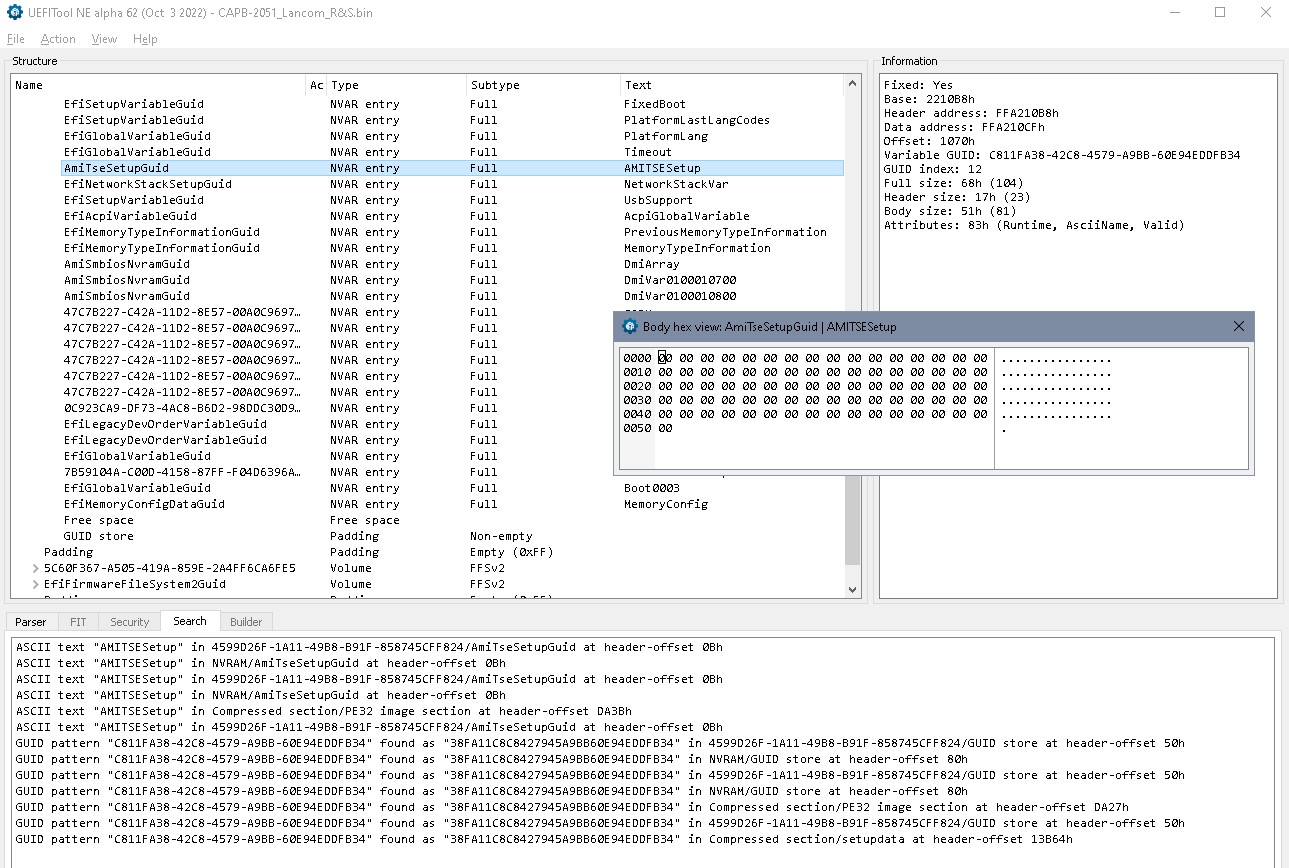
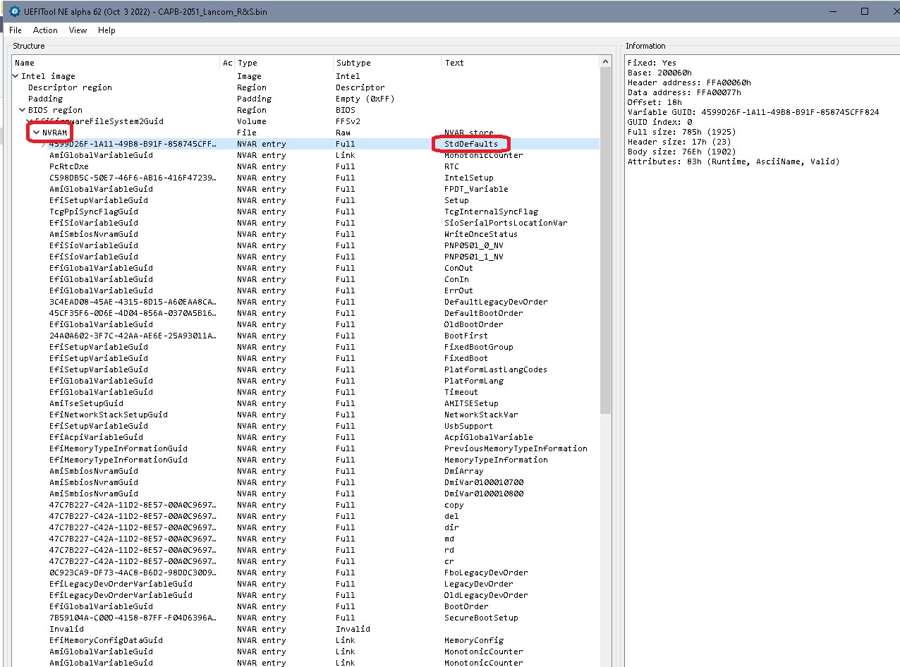
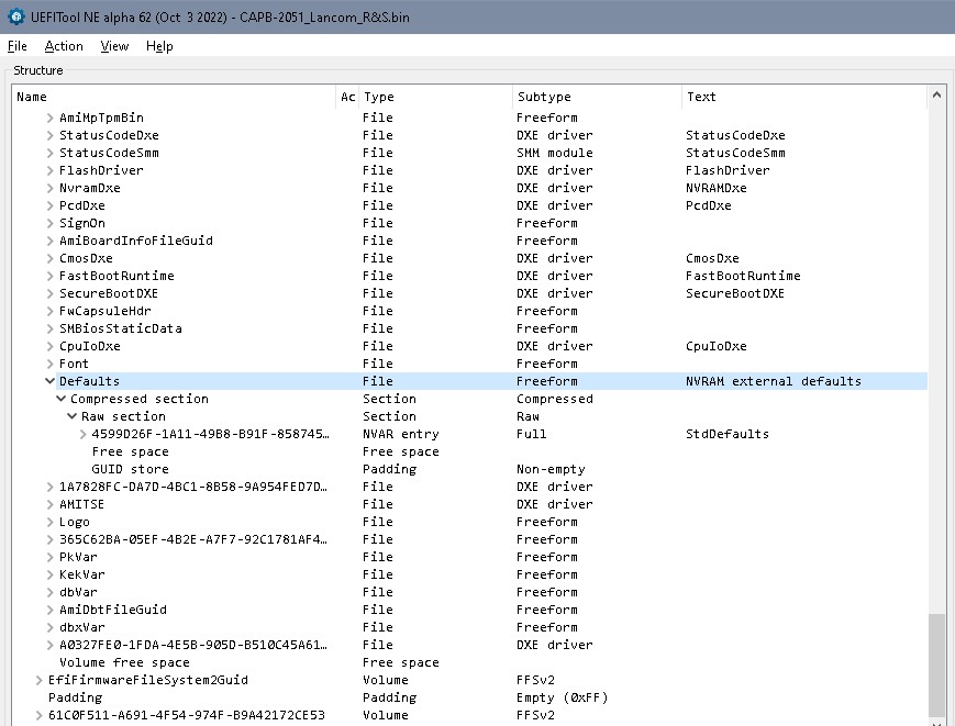
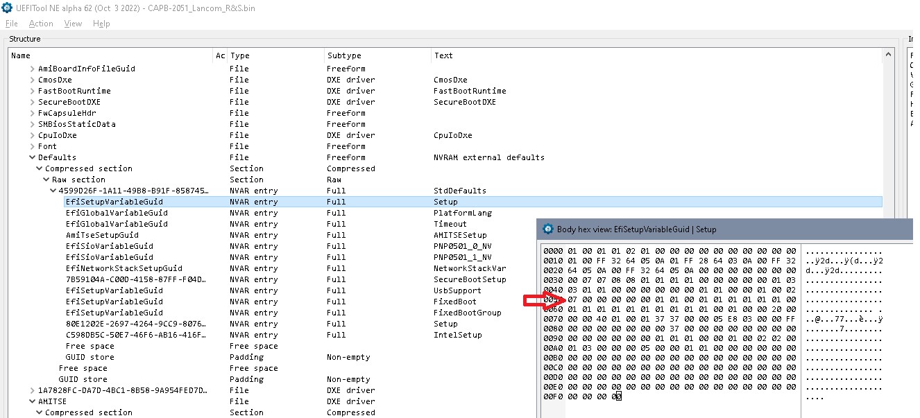
  • I examined two .bin files - the one I retreived from onboard BIOS with flashrom, and the one I got from Caswell - with AMIBCP tool on Win XP 64-bit PC (as I couldn’t find a reliable source for Linux version of AMIBCP). Everything looks fine there - no gibberish text in the Settings menus, all menus displayed as expected (according to printscreens in the CAR-2051 User Manual), all settings - Optimal and Failsafe - set to DEFAULT. I did try to search for the strings, that would give me a hint about the set Administrator password, but I couldn’t find anything. Either password is stored somewhere else (the Caswell guy claims it’s on BIOS, definitely not on TPM module, which I removed…), or I don’t see all the BIOS regions with AMIPCB tool. On the “Setup Configuration” tab there are “Setup”, “Recovery” and “IntelRCSetup” parent folders; the “Setup” folder contains a “Security” subfolder, with settings for “Admisitrator” and “User” passwords (all values set to DEFAULT). That’s it, there’s absolutely nothing related to ME region and SPI Flash Descriptor protection settings.

I haven’t heard from that Caswell tech guy ever since, as if my short lived pro bono unofficial B2C courtesy has expired … in the blink of an eye. The way I see it, even if I do everything right with the AMIBCP tool (all the right settings changed to USER, on all the relevant PARENT and CHILD levels), then flash successfully the empty SPI Flash with an external programmer, I’ll be still hitting the wall for not having the admin BIOS password. I’m hoping to generate some interest on this forum, in case anyone is keen to have a go at “cracking the nut” - finding/extracting the Administrator password from Lancom R&S BIOS .bin file, or offering a fresh approach at disabling it. I uploaded all the relevant files into Caswell CAR-2051 folder in my Dropbox, but I’ll gladly provide additional info, if requested.

Link:

Kind regards,
Bostjan

Open the dumped image in UEFIToolNE, if the password info is stored in the bios it’s almost 100% in NVRAM or a non-empty padding.

Thank you ‘lfb6’,

I see three different tools in the GitHub repo LongSoft (prebuilt packages) - UEFIExtract_NE, UEFIFind_NE and UEFITool_NE. If I get it right, I’m supposed to use … the third one ?

First I’d like to try the Linux 64-bit version, to see how it goes, unless you have a valid argument to have a go at Windows version instead. Will the 32-bit Windows version work OK on the Win XP 64-bit ? I’m not taking this for granted, hence my question.

This guide … Recovering the BIOS password from a Panasonic CF-U1 mk2 (AMI Aptio UEFI) … looks promising. Is there any other tutorial that you would recommend instead ?

Before I forget - beside the two BIOS images - the original Caswell .bin and Lancom R&S (current) version .bin, I also have a nvram dump, which I made with dd command. Looks awfully small in size though (mere 114 bytes), compared to 8MB of those two .bin files.

It’s a steep learning curve, admittedly so, once you cross the threshold of routine SAS HBA flashing and such, and venture into vast and intricate space of today’s BIOS-es scheme of things …

From 2019 onward AMI started to migrate BIOS passwords to TPM module, which did came plugged in the CAR_2051 board in my appliance (Infineon SLB 9655 TT 1.2, currently not plugged in), but luckily my Caswell appliance predates that AMI change.

AMI Announcement

Kind regards,
Bostjan

[UPDATE] None of the Win 32 version worked; tried A62 first, then older 0.28.0. Win XP 64-bit complained about both, reporting not valid 32-bit app (?!).

Tried with Linux A62 on Xubuntu 18.04.6, worked like a charm (no wonder … things have changed since days when Linux was a scary place for novices). I opened the Lancom R&S .bin file, and … have mercy ! It’s like sitting in the cockpit of Space Shuttle, trying to figure out which one among hundreds of buttons to press.

Found another tutorial with XOR-ing magic, with reference to article on GitHub. This XOR-ing wizardry may be easy-peasy task for those in the know, but it’s definitely out of my league. I really wouldn’t mind to be walked through with some “plain-English” step-by-step instructions, as for now I feel kind of “lost in the woods”. Everything I’ve been doing so far was a cakewalk compared to this …

Kind regards,
Bostjan

Well, there’s more ways to store a password…

But your bios setup indeed references AMITSESetup, if you use Universal IFR Extractor on the setup- see attached textfile, search for pass and you find that i references VarStore 0x6 which is “VarStore: VarStoreId: 0x6 [C811FA38-42C8-4579-A9BB-60E94EDDFB34], Size: 0x51, Name: AMITSESetup…”

Unfortunately all occurences I can see in NVRAM or defaults are zeroed.

So somthing is hard coded in one of the modules, or a password flag is set another place with no password stored, or some information in NVRAM is corrupt, or…

Easiest way to start would be emptying NVRAM and see how the system reacts.

Section_PE32_image_Setup_Setup_body IFR.zip (33.7 KB)

I see … had a look at the text file you attached, I won’t pretend I have the slightest clue how to interpret that data (the text and associated HEX values, found with “Admin” as the search string). Is this where the XOR magic would come handy ? The way I see, I can only hope that someone else will chime in …

Flushing the BIOS … would that refer to one of the CMOS reset methods, or do you mean something else ? The only tricks I haven’t tried yet, are the aforementioned cmospwd tool and the slightly odd ball Intel’s approach, described in the article “How to Clear the BIOS User Password and the Administrator Password on Intel Server Systems”. If you know some other hardcore “Swiss Army Knife” tools that are lesser known but effective, please do share …

Kind regards,
Bostjan

The text file is the extracted menu structure of the bios screens with associated storage location og the variables in NVRAM. No passwords hidden there, but only the references to the stores.

You might try your dumped firmware with an empty NVRAM, after flashing maybe several reboots needed.
CAPB-2051_Lancom_R&S_NVRAM.zip (2.5 MB)

Compare the structure in UEFIToolNE to your own dump.

NVRAM isn’t reset when clearing CMOS. By starting with an empty NVRAM one ‘presses’ the system to load the defaults and start from scratch. If a bios password is located somewhere in NVRAM it should disappear that way. But there’s no warranty, of course.

Hello ‘lfb6’,

my compliments for your enduring efforts, to help me with this challenge the best way you possibly can. Allow me to address your latest comments;

“The text file is the extracted menu structure of the bios screens with associated storage location og the variables in NVRAM. No passwords hidden there, but only the references to the stores.”

Got it.

"You might try your dumped firmware with an empty NVRAM, after flashing maybe several reboots needed … [CAPB-2051_Lancom_R&S_NVRAM.zip]

Thank you for doing this for me, as it would take me forever to figure out how to do it right

“Compare the structure in UEFIToolNE to your own dump.”

Compare how ? … perhaps by running one instance of UEFIToolNE to open the “CAPB-2051_Lancom_R&S” dump I made with flashorm, then running another instance of UEFIToolNE to open the file with empty NVRAM that you just sent … then what ? Hmmm, I don’t think this is what you meant … so how do I acquire that extracted menu structure from the .bin file you enclosed (what tool and what commands or GUI menu options) ?

“NVRAM isn’t reset when clearing CMOS. By starting with an empty NVRAM one ‘presses’ the system to load the defaults and start from scratch …”

This is where it gets real confusing for me. Isn’t that precisely what dozens online tutorial teach us, the CMOS reset methods as a remedy for problems that require reverting to factory default settings ? Aren’t “CMOS” and “NVRAM” one and the same thing ?

Here’s a random article, from Dell’s website, with instructions “How to clear the BIOS, CMOS, or NVRAM using a jumper on a desktop computer”. A couple of brief excerpts …

"WARNING: Clearing the CMOS or NVRAM using a jumper resets the passwords in the BIOS. This includes the BIOS user password, admin password, and hard drive password. This does not include any other passwords such as Windows login, online accounts, and so on."

“The Real-Time Clock Reset (RTCRST) jumper helps reset or clear the NVRAM on the computer. The ESCD information that is contained in the NVRAM can be cleared by following the steps that are mentioned below. The NVRAM is cleared when the jumper is set to the closed position and turning on the computer for 10 seconds.”

Granted, that Dell’s article provides a bit obscured hint, that “CMOS” may not equal “NVRAM” … "Summary: This Article explains how to perform a BIOS or CMOS Reset and/or clear the NVRAM on your Dell computer." To claim how this further complicates things for me, would be an uderstatement. Furthermore, if I do acknowledge that CMOS is not the same as NVRAM, then I really cannot fathom how the CMOS (RTCRST) jumper could selectively reset either CMOS or NVRAM, or CMOS and NVRAM, all that by user’s choice …

What am I missing here, be it obvious or not so obvious ? I’ve pretty much come to terms, that I absolutely have to dive into “deeper waters” - read a couple of lengthy .pdf books about BIOS and UEFI, since otherwise there will be fuses blowing in my head. Not only that, I do feel somewhat “guilty”, for wastings people’s time on forums as I didn’t do the proper homework.

" … If a bios password is located somewhere in NVRAM it should disappear that way. But there’s no warranty, of course."

Just a food for your thought … the Caswell CAR-2051 User Manual (I uploaded the whole document to my Dropbox folder “Caswell CAR-2051”) refers to several options regarding default settings:

1.) Aptio Setup Utility > [F3] shortcut key > “Load Optimized Defaults (Yes/No)”;

HINT: “The key allows you restore the user defaults to all the setup options.”

2.) Aptio Setup Utility > “Save and Exit” Menu > “Restore Defaults” > “Save as User Defaults”;

When that Caswell tech sent me a “virgin” CAR-2051 BIOS file, he clearly told me there’s a factory set Administrator BIOS password embedded inside the file (a feature request, as commissioned by Lancom Rohde & Schwarz). If I get it right, that admin BIOS password was set via “Save and Exit” Menu > “Restore Defaults” > “Save as User Defaults”, effectively making that a new “factory default” setting. So whatever stunt I come up with to clear the CMOS/NVRAM, it won’t do any good as it’s a default setting. Am I making any sence here ?

If I get it right, then AMIBCP tool clearly indicated, that none of the CMOS settings were altered and saved by user with [F10] “Save and Exit” - neither in the current Lancom_R&S BIOS settings nor the “virgin” Caswell BIOS settings, as all the settings I examined were set to DEFAULT. If the “User Defaults” as per CAR-2051 User Manual (also referred to as “Optimized Defaults”), and real - the one and only “Factory Default” settings, were a different thing, then I would understand where you were going with this "… If a bios password is located somewhere in NVRAM it should disappear that way … ".

Sorry if I sound “disoriented” here and there, I’m merely trying to draw some logic conclusions. Hopefully the fog in my head will clear any time soon, as I’m not really helpful with this troubleshooting, not as much as I wanted to be …

Kind regards,
Bostjan

'evening,

I just thought I should post a brief follow-up, with some conclusions and deductions I made, after reading a handful of articles and forum posts this evening. I’d like to show you where the bulk of my “problems with study material” stems from, as - first and foremost - my intentions to get to know things better are very sincere, so please bear with me …

The “NVRAM, RTC/NVRAM, CMOS, CMOS-RAM …” scheme of things;

While I could say that I’m getting really well acquainted with the “BIOS” chapter, I’m still banging my head about the terms in the paragraph tile (if and how they’re related), due to mind boggling amount of information, ranging from ambiguous, obscured, misleading, all the way down to incompetent explanations I found on the internet. No wonder I’m so mixed up, as I struggle to locate some known reference pages, where I could educate myself about BIOS and rely on the accuracy. To add insult to injury - a term “NVRAM” is often referred to as “volatile” and “non-volatile” RAM in the same sentence, rarely properly described as, let’s say - “conditional NVRAM” (for the sake or argument), while the terms “NVRAM” and “CMOS” are confusingly defined in (too) many articles, as you just can’t tell if “NVRAM” is referring to non-volatile RAM in general (as type of technology), or to an area on motherboard (SOIC chip, SB chipset, etc), where the BIOS/CMOS settings are stored.

Here’s an example, where the author fails to elaborate (IMHO), what exactly he meant by referring to “NVRAM” …

“It is worth mentioning that the BIOS settings do not have to be stored in volatile CMOS memory. There are plenty of embedded systems that store their settings in NVRAM.”

Source: Where is the BIOS stored ?

Perhaps it’s just me, and maybe the vast majority of members, on SuperUser or similar highly regarded forums, have no problems whatsoever, when things need to be put in the proper context, but … I do. Pretty much the same applies for usage of term “CMOS”, so to be honest - I really shouldn’t feel embarrassed (and frankly I’m not), for not knowing if NVRAM and CMOS are two separate silicon chips.

The “Default, User, Factory Settings …” scheme of things;

I could definitely benefit from mastering the clear distinction (or relationship) between settings that can be viewed with AMIBCP tool (“Optimal” and “Failsafe”), and the settings that can be altered, saved and loaded / restored by the user via AMI Aptio Setup utility, namely:

a.) “User Defaults”, loaded / restored with [F3] “Load Optimized Defaults” > “Yes”, or via “Save Configuration & Exit” > “Restore Defaults” > “Restore User Defaults”;

b.) Custom user settings, stored with [F4] “Save Configuration & Exit” or via “Save & Exit” menu > “Save Changes and Exit” (or “Save Changes and Reset”);

c.) Custom user settings, stored as “User Defaults” via “Save & Exit” menu > “Restore Defaults” > “Save as User Defaults”;

I would dare guessing that “Optimal” in AMIBCP relates to either “User Defaults” or any custom configuration stored with [F4] (all settings stored on CMOS/NVRAM), while “Failsafe” in AMIBCP relates to factory defaults settings (Read-Only, stored on BIOS - EEPROM or SPI Flash, hence not displayed in Aptio Setup Utility), which are loaded by BIOS if it finds the content of CMOS/NVRAM empty or corrupt.

Looking forward …

Kind regards,
Bostjan

The proposed way was meant to exclude one possible location where a password could be stored.

'morning,

thank you for getting back to me, appreciate your explanation. As you can tell from my lengthy follow-ups, I did study quite thoroughly the BIOS and NVRAM/CMOS topics last night (I had a graveyard shift, so plenty time …).

To summarize;

  • As far as CMOS Settings storage is concerned, I’m now confident there can only be one location (one dedicated silicon or integrated part of SoC), where those can be stored. Whether it’s battery backed CMOS SRAM, or a South Bridge, or some dedicated onboard NVRAM Flash (SD, CompactFlash, etc), that’s not really relevant from the settings location point of view. RTC may be a separate unit, though most of the time they reside on the same silicon. I just checked the [Atom C2000 Datashee](file:///home/sebastian_mws/Downloads/atom-c2000-microserver-datasheet.pdf)t and it looks like RTC and CMOS are both on the C2000 SoC.

  • I mentioned already that neither of BIOS .bin images - the current (modified for Lancom R&S) and original Caswell image - show any evidence of user defined admin BIOS password in NVRAM section. This implies that only a factory default BIOS password has been set by Caswell, and that one is not in NVRAM but on BIOS itself. Question that didn’t surface before is this one - where in the BIOS FW structure are the factory default settings stored ?

  • While desperately searching for the “hidden” magic tools, I did find a few very interesting projects, revolving around XOR decrypting tools (here’s one of them, called AMITSEDecrypt). If I just knew how to use them and where to locate that default BIOS password …

What can I say - what started as a mere out of spite crusade of mine, has quickly evolved into exciting learning experience. The initial goal of cracking the BIOS password menace is now merely a cherry on the cake, though I’d really enjoy it, you know … to solve the puzzle and claim the rights for that soul fulfilling sense of self content (shouting …“In your face, both of you - Lancom and Rohde & Schawrz !”).

Kind regards,
Bostjan

Interesting conclusions, but…

NVRAM is right before your eyes, part of the bios region and the defaults are normally part of the NVRAM EFI volume:

Often the defaults are also stored in a module in the volume with DXE drivers, like in your bios:

The Atom seems to have the CMOS with RTC builtin and it has a lockable range. That’s more interesting- so you might possibly find the chipset register, look into the chipset NVRAM store and check if the coresponding bit is set…
But that’s just a theory, maybe the password is hardcoded in the corresponding bios module …

Hello, ‘lfb6’,

after getting more and more desperate, for not finding concise online literature that would “fix my compass”, as in - set me on the right course of understanding the legacy BIOS and its EFI/UEFI successor, along with CMOS/NVRAM role of storing user defined BIOS settings for both, I had finally found an article that offered some new clarity, compared to pages upon pages of useless Google hits that have been cluttering my “fishing net” over the course of last few days (dozens of half-baked articles, with non-explanatory BIOS and UEFI structure diagrams, getting me nowhere…).

This is the article that made all the difference …

“NVRAM device in UEFI-compatible firmware, part one”

Thank God for this piece, it’s truly godsend … now I finally have the clue about what you’ve been telling me the whole time. I’m beginning to understand that grasping the knowledge you already shared, and to follow in real-time the lessons I’m hoping to receive in your sequels, will require a rather profound shift in my mindset, a genuine effort to understand the difference between how things were done in legacy BIOS architecture, and how it’s done nowadays in UEFI (the common basics at least, just enough to be “on the same page” with you …). I’ll get back online as soon as I “connect a few more dots”. Like I said - I wanna be a worthy “student”, so I need to do more homework …

Kind regards,
Bostjan

Hello, ‘lfb6’,

So where was I …

If I get it right, my default, as in - factory settings (would that be “Failsafe” in AMIBCP ?) are stored in NVRAM (NVRAM EFI volume) on my Winbond SPI NOR Flash - a.k.a. - “the BIOS Firmware” chip, along with basic UEFI drivers, while the user defined settings are in CMOS region (configuration, peripherals settings, etc), an integral part of Atom C2000 SoC, same as battery backed RTC for Date & Time.

A couple of comments …

“That’s more interesting - so you might possibly find the chipset register, look into the chipset NVRAM store and check if the corresponding bit is set…”

I’ll be … if I knew how to go about this, as in - where to “find the chipset register” (Atom C2000 Handbook ?) and how to “look into the chipset NVRAM store”

“But that’s just a theory, maybe the password is hardcoded in the corresponding bios module …”

Seems more and more likely to be the case. Locating end decrypting the “hard coded” admin BIOS password would be a real blessing. Would the XOR decryptor come handy here (like XOR Cipher, for example), or any other tool that hasn’t been mentioned in this thread ?


In the meantime I received the long awaited SOP8 200mil to DIP8 adapter and a couple of Winbond 25Q64FVSIG chips, tried to flash one with Batronix BX programmer, but … I encountered an error during “Erase chip” stage (“bulk io error”. The erase phase continues till 99%, then it stops and never completes. I already opened the Tech Support Ticket, might take a while …

Still not throwing in the towel, though I fear I’m approaching the end of the road with my zealous crusade …

Kind regards,
Bostjan

Most of the system settings are in NVRAM = within bios firmware

For most of the bios settings you can find an explanation in the textfile I attached earlier (Section_PE32_image_Setup_Setup_body IFR)

For example:
Gray Out If {19 82}
0x11E89 QuestionId: 0x182 equals value 0x1 {12 06 82 01 01 00}
0x11E8F Password: Administrator Password, VarStoreInfo (VarOffset/VarName): 0x28, VarStore: 0x6, QuestionId: 0x13F, MinSize: 0x3, MaxSize 0x14 {08 91 45 04 46 04 3F 01 06 00 28 00 00 03 00 14 00}
0x11EA0 End {29 02}
0x11EA2 End If {29 02}
0x11EA4 Suppress If {0A 82}
0x11EA6 QuestionId: 0x182 equals value 0x1 {12 86 82 01 01 00}
0x11EAC QuestionId: 0x182 equals value 0x0 {12 06 82 01 00 00}
0x11EB2 Or {16 02}
0x11EB4 End {29 02}
0x11EB6 Password: User Password, VarStoreInfo (VarOffset/VarName): 0x0, VarStore: 0x6, QuestionId: 0x140, MinSize: 0x3, MaxSize 0x14 {08 91 47 04 48 04 40 01 06 00 00 00 00 03 00 14 00}
0x11EC7 End {29 02}
0x11EC9 End If {29 02}

Find VarStore 0x6 listed in the beginning:

VarStore: VarStoreId: 0x6 [C811FA38-42C8-4579-A9BB-60E94EDDFB34], Size: 0x51, Name: AMITSESetup {24 22 38 FA 11 C8 C8 42 79 45 A9 BB 60 E9 4E DD FB 34 06 00 51 00 41 4D 49 54 53 45 53 65 74 75 70 00}

Look into the NVRAM defaults and into the used NVRAM and you find an item either by name or GUID that fits, has body size 51 (but of course it doesn’t give you the password as we already know)

Same is valid for chipset registers / chip set configuration- that’s normally the store ‘setup’ or ‘intelsetup’

Example:
VarStore: VarStoreId: 0x1 [EC87D643-EBA4-4BB5-A1E5-3F3E36B20DA9], Size: 0xF4, Name: Setup Size 0xF4 = 244

For example:
One Of: Bits per second, VarStoreInfo (VarOffset/VarName): 0x50, VarStore: 0x1, QuestionId: 0x25, Size: 1, Min: 0x3, Max 0x7, Step: 0x0 {05 91 4D 02 4E 02 25 00 01 00 50 00 10 10 03 07 00}
One Of Option: 9600, Value (8 bit): 0x3 {09 07 4F 02 00 00 03}
One Of Option: 19200, Value (8 bit): 0x4 {09 07 50 02 00 00 04}
One Of Option: 57600, Value (8 bit): 0x6 {09 07 51 02 00 00 06}
One Of Option: 115200, Value (8 bit): 0x7 (default) {09 07 53 02 10 00 07}

So the value for this setting stored in the defaults is “7”, the default.

Not all values are referenced, not all stores have extractable information within the bios region…

I’d assume the locking for those 2 lockable CMOS region is done by the bios at boot and it’s just one bit somewhere in the NVRAM defaults.

'evening ‘lfb6’,

what an elaborate article, I feel honored … will take some time and then some, before I’ll be able to “digest” the content of your BIOS & UEFI Curriculum, which has amounted quite a bit through our correspondence.

Some good news - after an all day ordeal with installing the software for my Batronix programmer (turned out it requires mono to work properly, a nightmare on its own…), I wiped the mess from my Ubuntu laptop and grudgingly install Win XP version of that software on my “last-resort” PC (for Win* stuff that can never be replaced by GNU/Linux apps, like CorelDraw…). It installed with minor complaints (USB driver), but ultimately it worked just fine and I was able to flash the SPI Flash chip with Caswell version of BIOS image … success ! I quickly swapped the current BIOS chip with freshly flashed one, and … it worked ! … for the first time I was able to see the pre-boot environment on the primary console port. It was a short lived joy though, as pressing the “TAB” key confirmed my fears (and Caswell guy’s disclaimer) … it’s password protected, just like the .bin I dumped from Lancom R&S version of BIOS.

But here’s another (potentially) good news … I may be onto something, with AMI tool called AMICSE. For your convenience I uploaded the User Guide to my Google Drive (Dropbox is getting more and more restrictive for free accounts):

“Aptio AMISCE 5.04: User Guide for Intel Server Board M10JNP2SB”

For the time being I wouldn’t be overly concerned that this guide refers to specific Intel server board, what matters is that the guide revolves around Aptio 5 with references to EUFI version of this tool. Here are the chapters / paragraphs that caught my attention:

  • “Raw import mode” (p.17)
  • “NVRAM Variable Access Unlock” (p.18)
  • “Change User/Admin Password” (p.18)
  • “Examples of password types used with password switches” (p.19)

Admittedly there are warnings that manipulating the variables requires BIOS administrator password, but not all is lost, as then follows this paragraph …

  • “Examples of how to clear and create a new admin/user password” (p.20)

Is it just me or is this actually a promising route ? Granted, there’s a note below …

“Note: The BIOS must be configured to allow clearing and creating passwords. This feature is only allowed in the EFI version of the tool.”

… but that’s something that appears to be doable with UEFI version of AMISCE, with prior intervention in the settings (with AMIBCP tool), to change the permission settings for Administrator password, from “DEFAULT” to “USER”.

Let me know what you think of this, OK ? I already searched for AMISCE tool on the web, but for now all I got is a couple of links to VirusTotal flagged archives (they could be false positives, but I’m not foolish to gamble…). What I’m after is the latest at the time available AMISCE for Aptio V, version 5.03.1115, be it for Linux x64 or Win XP x64, the UEFI version or a bundle that contains it.

Kind regards,
Bostjan

I’m sorry, I’m out of it at this point.

I don’t think you’ll find a tool that will let you remove a password without asking for the password, so it’d be a backdoor like finding the bit for locking the CMOS for reading and writing, changing it in NVRAM and so be able to read the encrypted password in NVRAM and then to decrypt it (if the password id stored in these regions in CMOS/RTC).

Good luck!

Hey lfb6,

nothing to be sorry about, really. I was prepared from the onset, for the slim chances of successful closure of my post (to be marked as SOLVED). The fact that the core of my topic was a rather exotic system board, was not exactly a good incentive for others to join in, I know that. For what it’s worth - you were the only one who even bothered to come forward, as I posted my plea on two other BIOS related forums, where there was zero response (not counting moving my post by admin, from a perfectly legit “BIOS Unlock Request” forum section to General section that no one ever reads).

I can understand there’s only so much time a person can devote in his/her spare time, for “lost cause” riddles like this one, but then again - I have no regrets. At least for me it was a worthwhile journey, topped with my final resolution not to give up entirely, as it would be a shame to bury the whole thing, after so much effort and time was invested, yours and mine. For the time being I’ll set this project aside, but will give it a nudge every now and then.

As for your arguments regarding my false expectations, I’m referring here to my latest discoveries about AMISCE tool potentials;

In all the excitement I made a mistake and misinterpreted the syntax of AMISCE command for erasing the admin BIOS password. What I thought was an actual syntax for specifying the currently set admin password (current_password), turned out to be a verbatim expression for “current password”. In Linux universe the commands in manuals are written in widely known orderly manner (standards, or command line “basic grammar”, if you want), to avoid confusion about what is a command, option, argument, file or directory, and what is a reference to symbolic text (a.k.a. - verbatim, which BTW should be encapsulated by left angle and right angle brackets). Apparently AMI didn’t see it necessary to adhere to any standards whatsoever, but that’s a topic for other places, not here …

Thank you once more, it was a pleasure …

Kind regards,
Bostjan

I am in a similar predicament. Have an extremely useful c2000 atom network appliance and can’t use it. I’ve dumped the BIOS, read everything I can find and am largely where you are. Maybe we can collaborate in this insane process?

Let me know. I’m going to keep forging forward.

Hello lfb6,

I have a few Nokia nuage networking devices.
With the NSG-C I could find the BIOS password through the method of Xoring the content of AMITSESetup with the multiples of 5B93 like in Recovering the BIOS password from a Panasonic CF-U1 mk2 (AMI Aptio UEFI) (github.com).

However, with NSG-E200 (Advantech FWA-1010VC device) and NSG-E (Lanner FW-7525 device), it is not so easy as the AMITSESetup is filled with zeroes as in this post.

I’m going to give a try to flash a modified BIOS with empty NV-RAM. I see in the file you uploaded for the CASWELL device that all the NV-RAM entries are empty but I wonder how you performed this.

With UEFITool I can’t remove NVRAM entries.

Here is my bios: NSG-E202.rom

Many thanks for your help.

Kind regards,
Kevin.