The motherboard supports Serial ATA II hard drives and Intel® Embedded Server RAID Technology II. Now, I want to upgrade my storage with PCIe NVMe controller and NVMe disk. I updated the BIOS with the last version (enclosed) and unsuccessfully tried to plugin the NVMe module through the PCIe controller. I wonder if it is possible to modify the BIOS of the INTEL S1200BTS/c202 chipset motherboard to support NVMe.
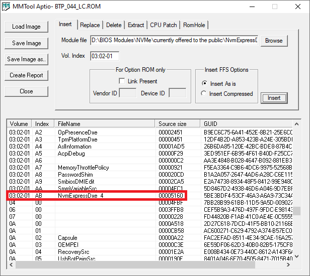
@YuryG : Welcome to the Win-RAID Forum! It is no problem to get the NVMe module inserted into the BIOS file named BTP_044_LC.ROM (see below picture), but I am very unsure, whether you will get the modded Intel BIOS properly merged and flashed.
@YuryG : It is possible to modify an Intel mainboard BIOS, but extremely difficult or even Impossible to get such modified BIOS successfully flashed into the mainboard’s BIOS Chip (due to Intel’s security efforts to prevent it).
Yes I got it flashing a BIOS into S1200BTS. You’d need a 2nd running computer for that. I used my external Programmer TL866II+ via ICSP an SOIC/Clip/clamp and a breadboard, flashrom and other programmer shoulod go too.
Though Lost_N_BIOS warned me not to do it while board is running (PSU on and mainboard switched on).
The problem was, my programmer (most probably also others), could not detect chip ID, when PSU off and when PSU swirched to 1. It also interestingly did not detect CHIP-ID when PSU is 1 and when mainboard is powered via Power-Switch-Button.
So did a trick, with some kind of "egde triggered reset" mentioned here as one possible way to try out: https://www.flashrom.org/ISP
This trick did flashrom method with edge triggered reset mentions did not work entirely, so I changed this method a bit. The trick was putting a paper clip on to the ATX 24-Pin-PSU-connector (from 24-pin connector: conducting GREEN with Black) from the above, while the 24 Pin PSU-connector is plugged in the mainboard-24PIn-ATX-Header (while PSU is OFF !!) (Putting paper clip from above while PC and PSU is switched OFF for better safety. Then when sure paper clip holding steady in PSU connector, (PSU remains OFF) I put SOIC clip/clamp which is actually for 150 and 200 MIL sizes (but works too) via ICSP connected with my programmer onto the big Winbond W25Q64FV or might be SW25Q64BV (same chip ID) big (300 MIL) version. — (MAKE sure that you programmer has OFF-protect and shortcut-circuit protection) and if not and yxou want to risk frying your mobo, make sure, that SOIC clip is always attached correctly and fixing good , and SOCI-clip pin1 (red colored able) turned to corresponding dot mark direction as EEPROM, and (watch and check attached clip and chip also from side and from different directions) and that holding steadily, and all stuff seated, that you don’t move against s.th.
Now powering on S1200BTS. Now the issue was programmer could read Chip ID from W25Q64FV via ISCP oof soldere S1200BTS, but only for ca 3 seconds periods with alternating periods only reading 0x000000 and again the chip ID. Without powering and that trick I always got FFFFFF. This hekped maybe, probably ME firmware blocking sometimes SPI access, in exchanging periods and ME crashig or and rebooting st.h like that, releasing access back to programmer or so.
Gotten a bit further, still the porblem was not long enough time in period.
The next trick was, waiting until next period is beginnin to start recognizing Chip ID again, then at once putting a jumper on the power-pins-switch, and then at once a second jumper to resset-pin, and/or changing the jumper to from power-sw-pin to Reset pin to POWER-SW after that (or I did versa, not 100% certain or 2nd jumper). Tje jumper placing and/or changing to other sort of SW had to be in get-Chip-ID period. – The difficult thing is catching the start of the getting-chip-ID-period, before ME has finished booting, so that you have as much time as possible for placing jumper and changing jumper position. So it might be that you have only ca. 1-2 seconds max of the 3s-getting-chiop-ID-time-frame.
Before starting plcacing jumper , With the minipro software I just click on "read Chip ID" icon, if you can repeat quickly this step, this helps timing the start of getting-chip-ID more precisely. Afaik the get and/Not get Chip-ID period are both alternating in repating same time-frame-periods, which helps a bit more. [Edit] So I think I rather placed the jumper first to reset, which cuases automatic reboot mainboard+ME firmware after ca. every 8 seconds. So I zhink I then jumper from Reset to PWR-SW-pin, and/or used a 2nd jumper to the PWR, while 1st one is on RST-SW. One of the two done within ca. 1-2 seconds within at correct moment where it starts getting-Chip-ID-phase. —
If did not place and replace kumper within e.g. max 1-2 seconds, it couldn’t read chip anymore temporily for this powered on-phase. So I had to repeat, powering off PC, removing jumper from RESET and/or Power-pins, then powering S1200BTS (again via GREEN and black and 24pin conencted from the top of 24 pin), waiting until period where it detects Chip-ID arrives, and doing agaibn with jumper on reset and/or power pins at first as fast as possible where ca 3 seconds gets Chip ID, and within that period at once change jumper it to reset and or power pin.
Now programmer could read chip ID steadily. — With luck managed that somehow, I had to try all that ca 2-3 times, then succesfully got Chip ID steadily, and able to read EEPROM, and erase and write it (Checksum identical). In some occasions programming and/or reading was not 100% reliable, mostly writing so I had to retry wrting a 2nd time. But then data identical.
@YuryG Edit] As far as I understood @Lost_N_BIOS , writing a recovery image with any of the three with programmer is WRONG!! It is just for recovery routine from EFI shell mixing missing code from R0044Rec.cap together with one of the three recovery images.
[Guide] Manual AMI UEFI BIOS Modding (28) Below IS NOT recommended -------------------- ATTENTION: Make sure you arer writing the correct image if BTP_044_LC.ROM was correct one. I’m not sure which is. There are three recovery images , BTP_044_LC.ROM BTP_044_RM.ROM, BTP_044_RM.ROM, and make SURE flashing via ISP/ISCP was error-free (see why possibly so extremly important, see below)
-– But only one of them is suitable for S1200BTS. So be careful. I don’t know which one. So please DO NOT POWER OFF S1200BTS (while board is in mode to get Chip ID stable), until you’re sure that you have written correct recovery image (8192 KiBytes) to EEPROM via ICSP!! ----------------------
I had flashed a wrong one, while programmer could read and write chip steadily. But after repowring S1200BTS, and it didn#t boot (because pciked wrong one), the above trick no longer seemed to work so far, only seemd stuck with the read-Chip-ID-and-not-read-chip-ID-exchanging period. Maybe I didn’t retry it as before, not 100% sure. (But I can rule out an electrical short here).
Writing a recovery image with any of the three with programmer is WRONG!! This couldn’t work anyway with those three files, needed a backup-dump!! @Lost_N_BIOS Sry I didn’t check forum, yes I have made backup dump, at least from the before-state with the modifed R44.cap (updated via EFI shell), where PC seemmed to run fine, but crashed during memtest, and no longer booted, only LED shining. I can post it in the other thread where you asked for it, if worth looking for me and/or you. I had soldered out EEPROM, after I no longer were able to read/program it via ICSP. But my S1200BTS is broken anyways, after soldering EEPROM out, in the meantime, the SOIC-Pads are oxidated and some thin through-connection -copper-wires around the SOIC-Pad area have woved off from the heat with the air gun. I still ahev the baord, maybe I can repair the SOIC-pads it with fresh copper and some kind of epoxide-gum glue.
So as Lost_N_BIOS and Fernando and woulod recommend.
First make backup-dump, via ICSP/ISP (In-circuit-serial-programming/reading), only reading out EEPROM with the above descrobed trick with Green and black and jumper etc, but do NOT flash anything yet.
Then modify this dump with the microcodes you ant to update and maybe other stuff.
Then flash this dump with above trick. Before doing that, maybe I’d ask s.o. if the then modified dump looks valid, so that the board will mostz probably boot.