You should measure the circuit to the SPI when CMOS battery is present.
This is a 1,8v IC if not mistaken…not reading upper posts… the PSU should be 3,3v stand-by power and this always the last thing to try. Theres the risk of damage to the CH341 or IC.
Many Macs and pc laptop boards require PSU on but this is desktop motherboard with 3,3v CMOS and it all depends on the motherboard circuit design.
You should confim this with that user from the thread i previously linked.
He did tried with PSU and no results.
He confirmed the connection established after post #15
Even with a brand new set as you just build, theres still the “tiny” issue of correct contact, it may look correctly connected… very common on this clips.
Do please keep in mind that all my guidance is given by general knowledge and i im not going to confirm it personally all this details, every time a user asks help on a subject… i would not live my personal and professional life if i were to loose time to this forum or any other forum with such technical details to each user/issue, im sure that you know and understand what i mean…
Regards.
I couldn’t read the IC soldered on the motherboard.
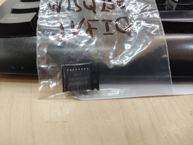
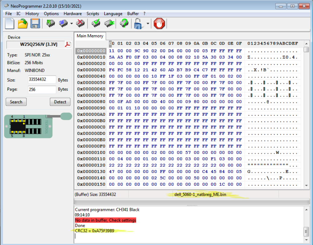
To test I bought 2 chips 25Q256JVFQ (same as on the motherboard) to try to read.
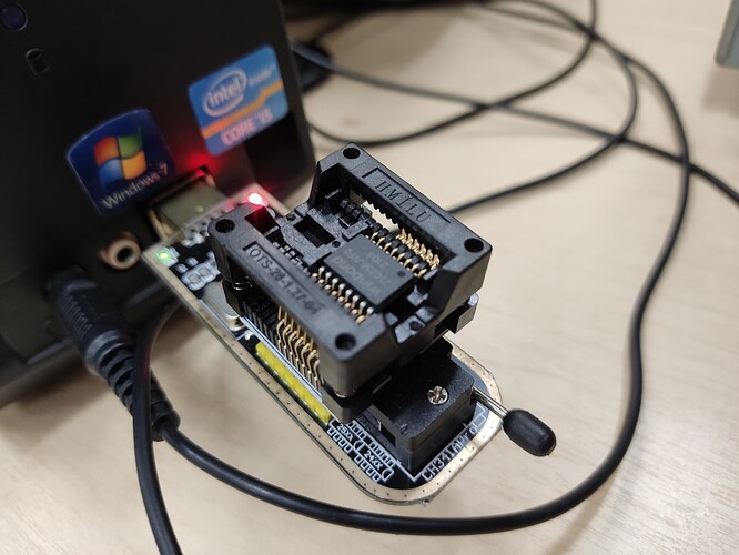
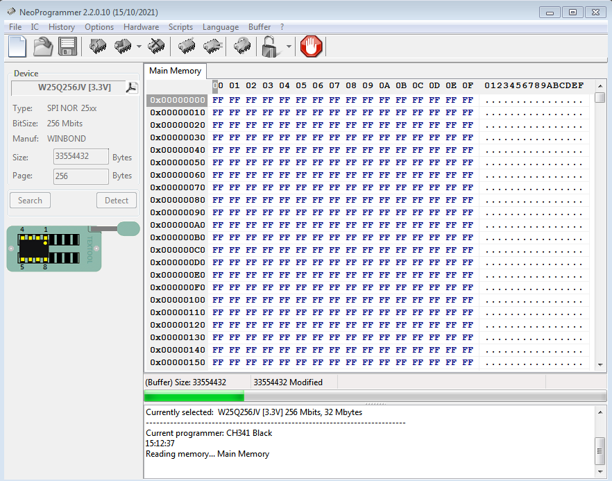
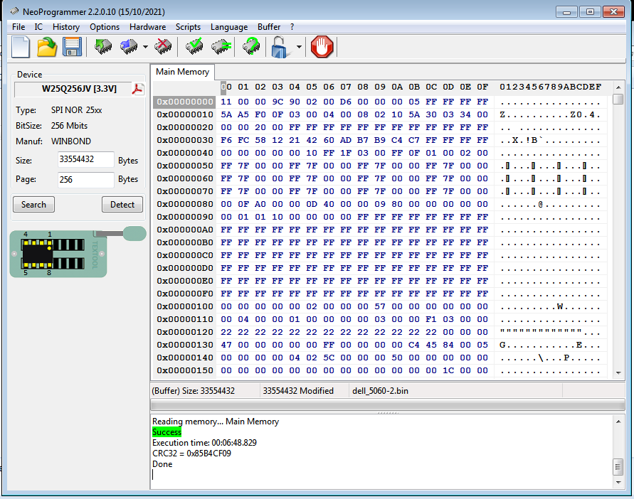
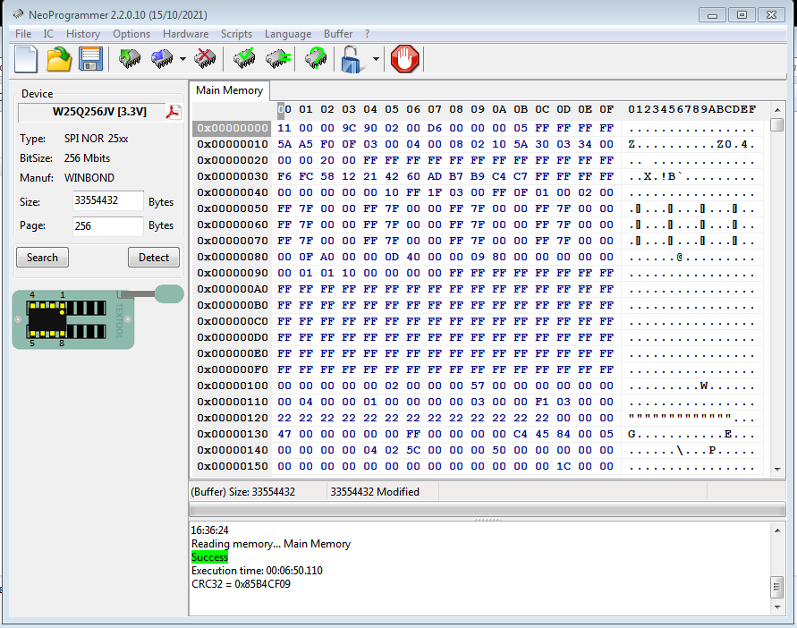
On the first try, the CH341a detected and read the IC normally.
Now I’m going to try to unsolder the IC from the motherboard to try to make the backup.
If it works I would like to have your help to try to record the new one, because it seems to me a very complicated task.
Thanks
Sorry, I forgot to try to upload the compressed file.
Uploaded file
Thank you for being patient in helping. I have no experience performing this procedure.
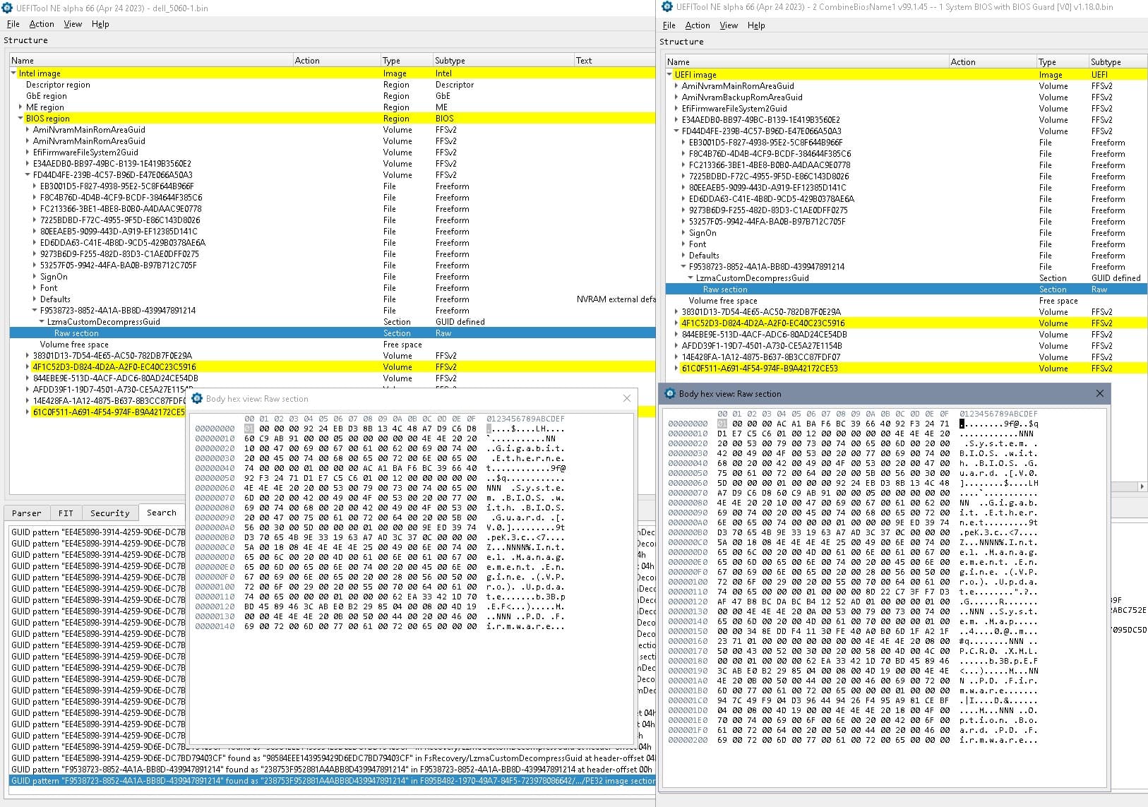
That’s your firmware with a stock bios, DVAR block transfered (0x1081000, size 0x10000), ME clean / freshly initialized according to
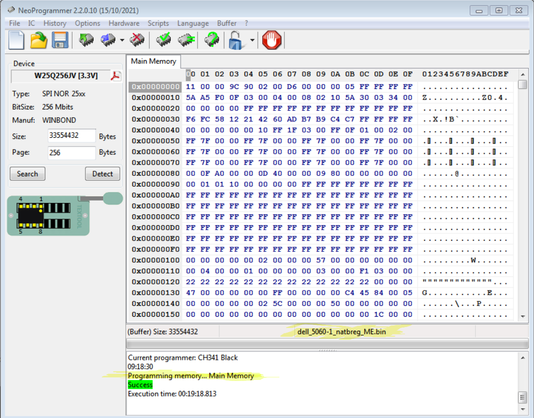
After programming dump the chip again in a separate process, save the dumped content with another name, and compare it to the original file. They should be a 100% identical.
(If this works and in case you should have to work again on the firmware- it’s the folder with “2 CombineBiosName…”)