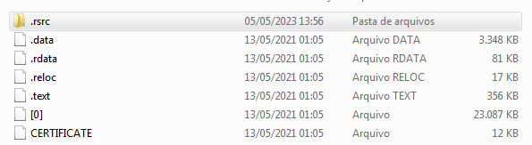
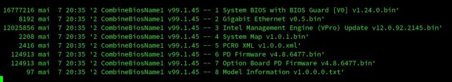
Not only that, Dell doesn’t deliver a complete firmware image but only bios region. So you’re missing FD, GbE and ME and need them from your own firmware…
I had flashed BIOS before, but it was one of those old ones. I simply downloaded it from the company’s website and recorded it. These newer ones are much more complex and I have no knowledge. Could you point me to literature for me to try to understand the structure of SPI Flash? What are regions and what does each one do. For example: what do the FD, GbE and ME regions mean? Thanks so much for helping.
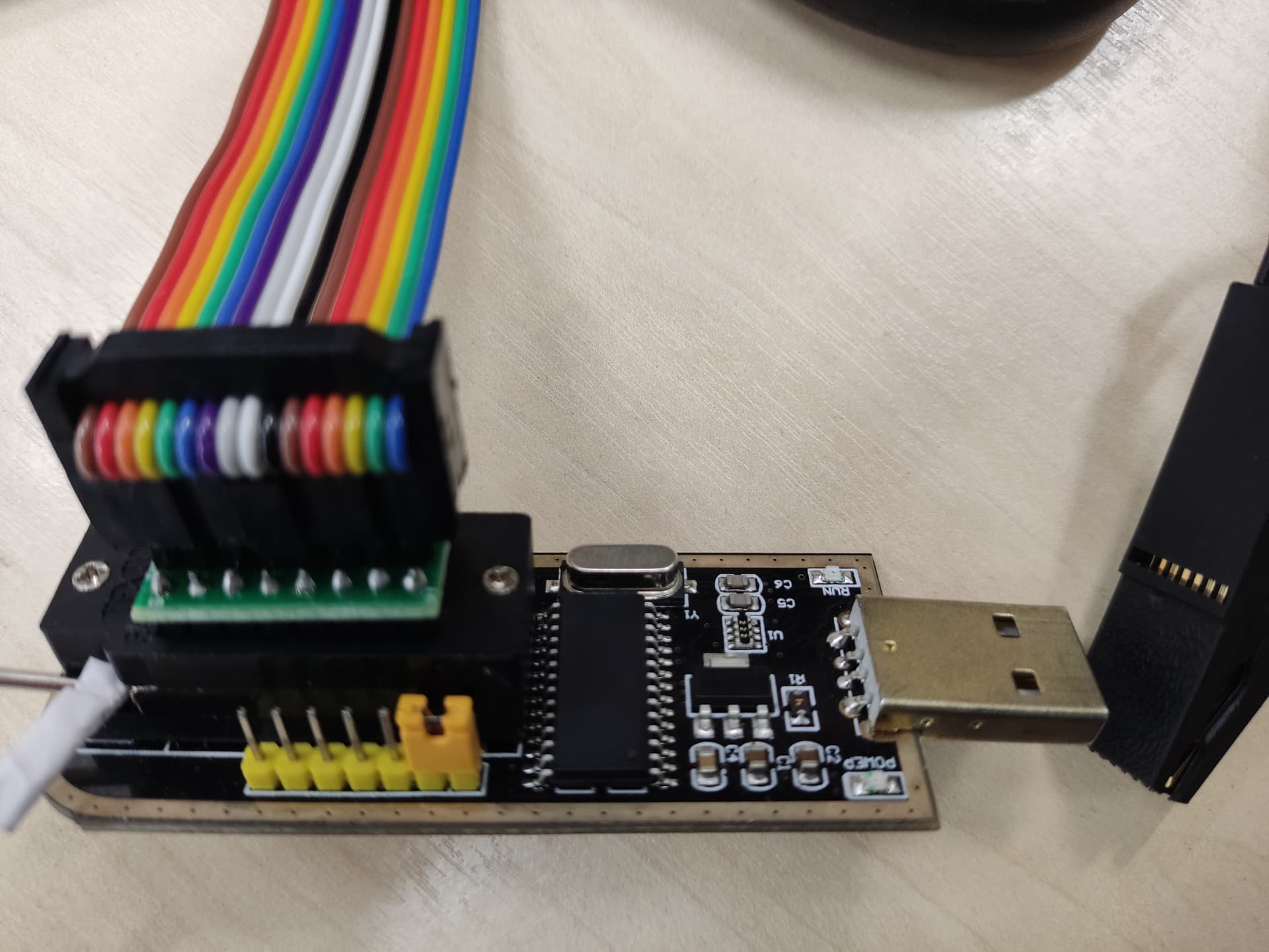
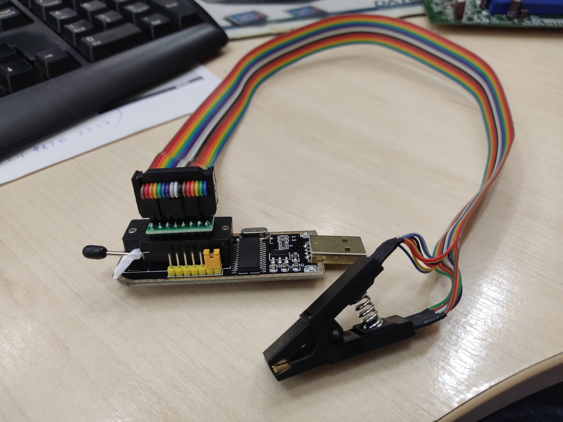
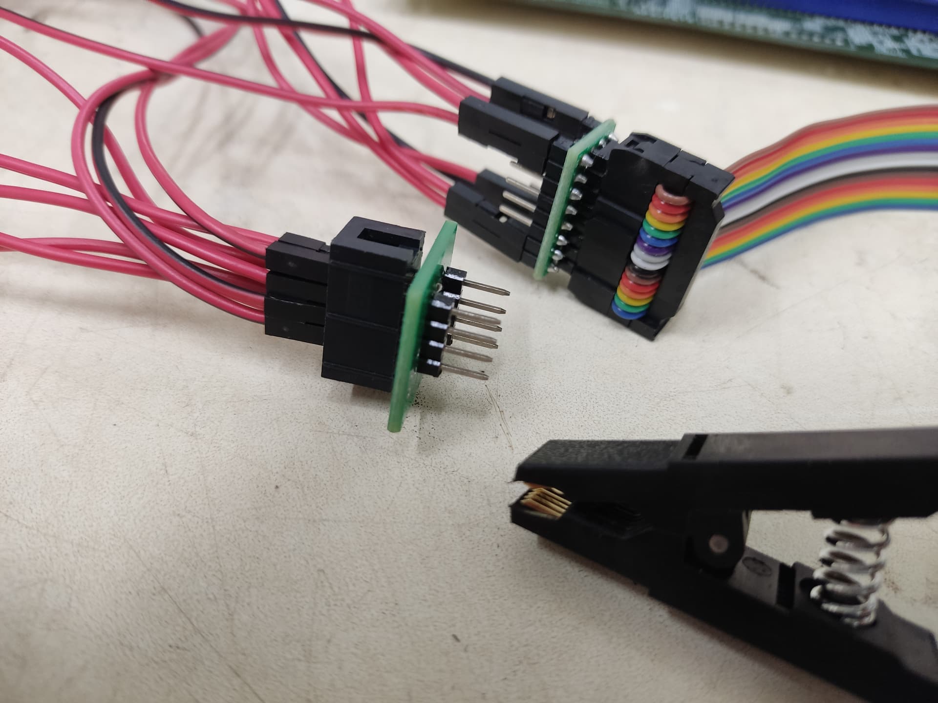
Well in case that no one told you before… these cheap CH341 requires a correct pin contact from the clip that is not always easy to get, besides the view of human eye it may seem ok but its not… several attempts must be made.
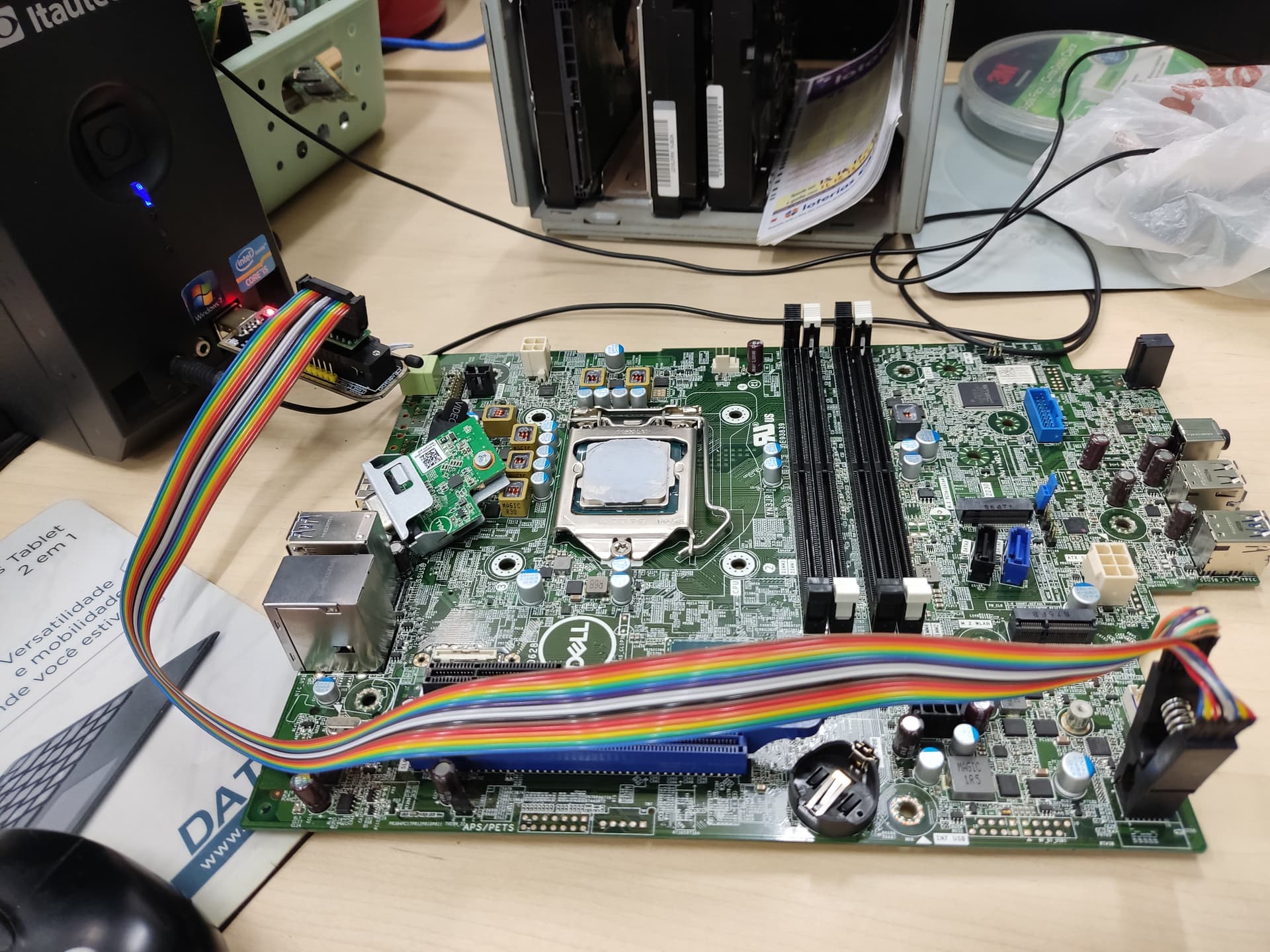
Also there’s motherboard circuits that may require CMOS 3,3v present and/or ATX PSU power standby and depending on SPI required voltage 3v or 1,8 range.
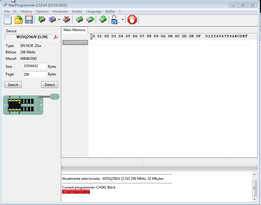
Do not select the SPI model manually, the app when in correct connection should identify the SPI.
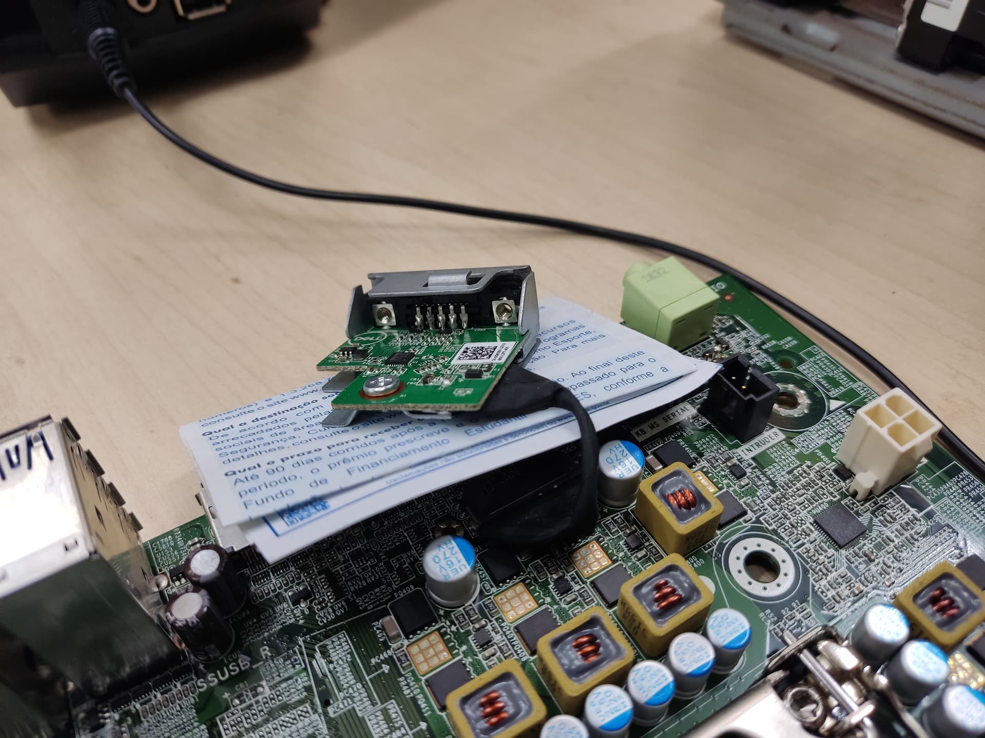
Sidenote…we shouldn’t have pcbs scattered across the motherboard… that may cause connection to circuits… i see that metal from the vga header touching the pcb…
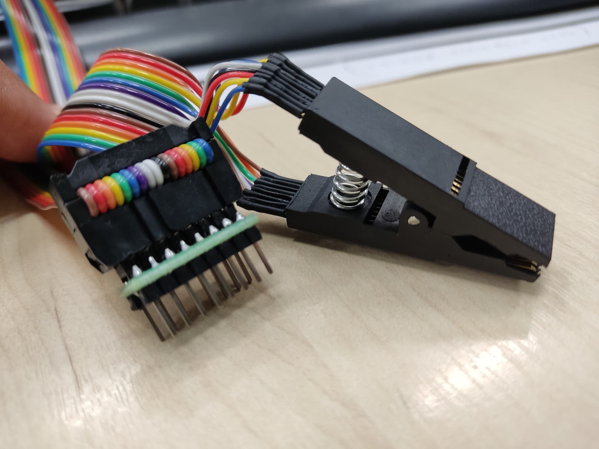
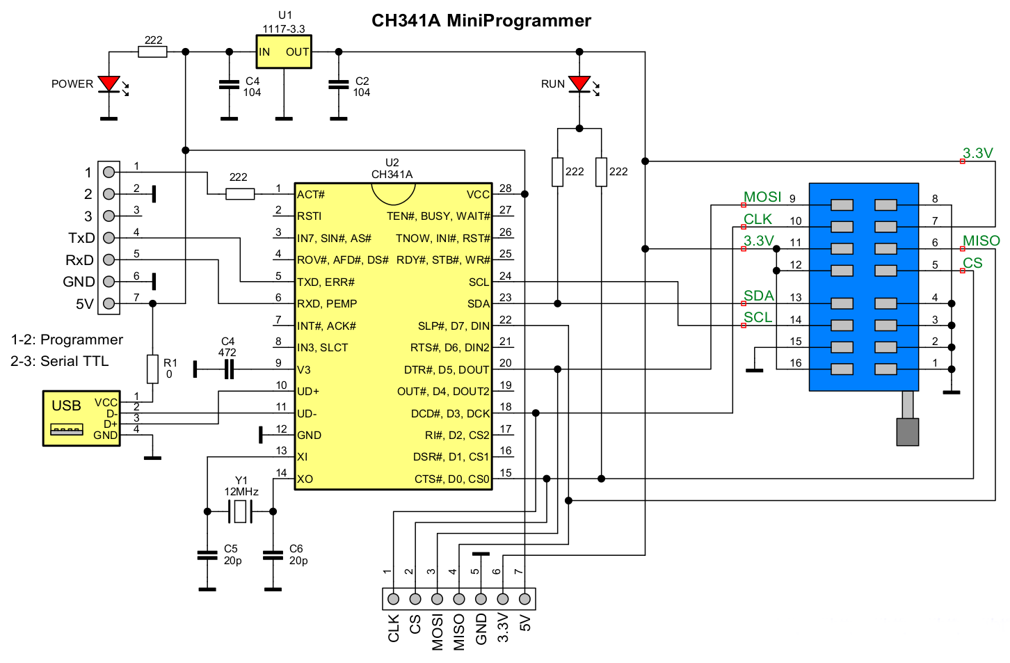
8 pins of all my ch341 sockets is 25type SPI, the other half 24xx type, normally it’s printed on the board.
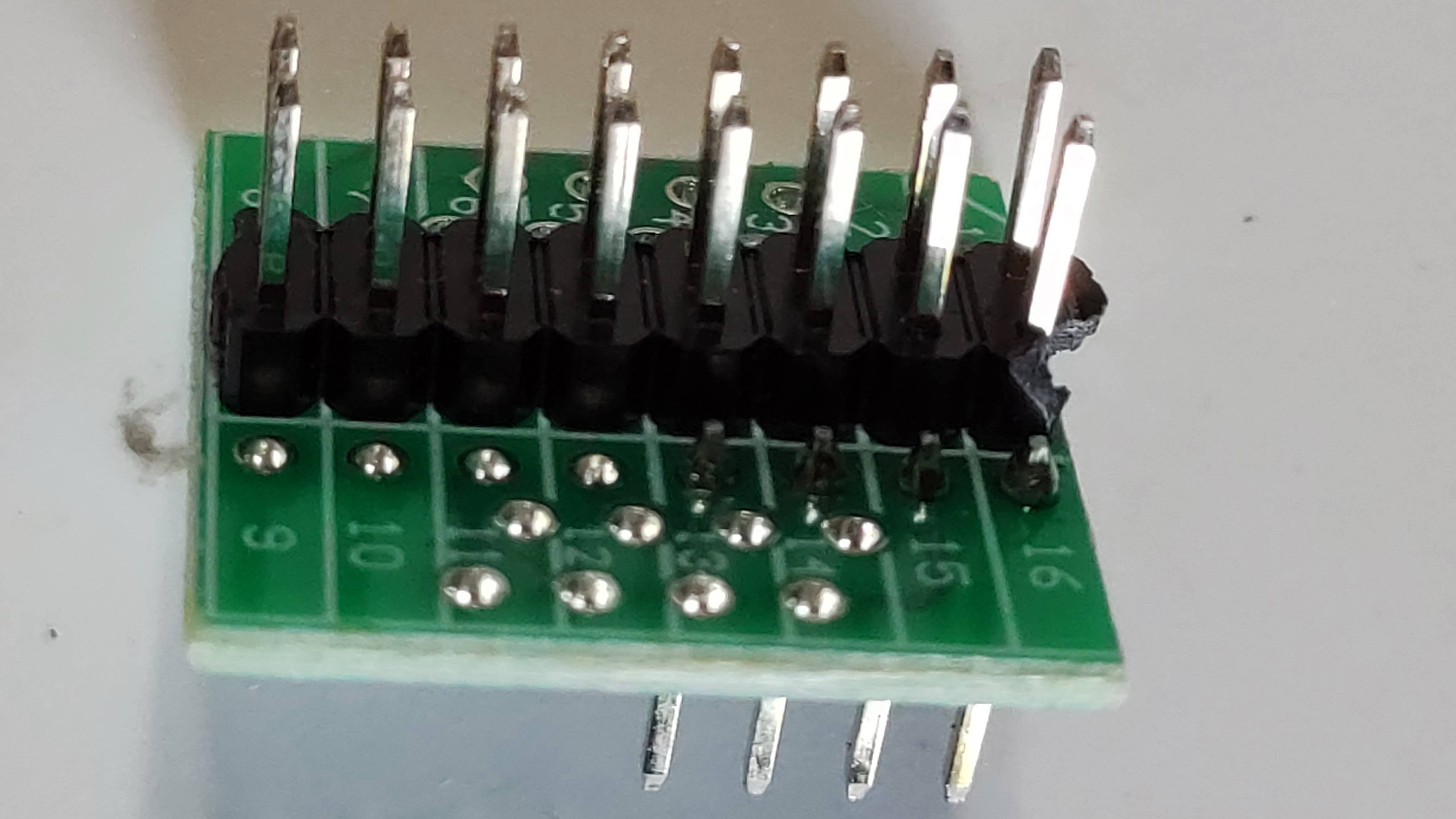
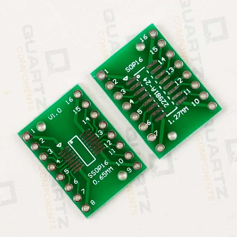
Most SOIC 16 have only 8 pins connected, you’ll have to sort pins/cables yourself!
Optimism normally is considered a positive thing but just putting things together since it looks good without knowing what one’s doing might shorten the process in an unwanted way.
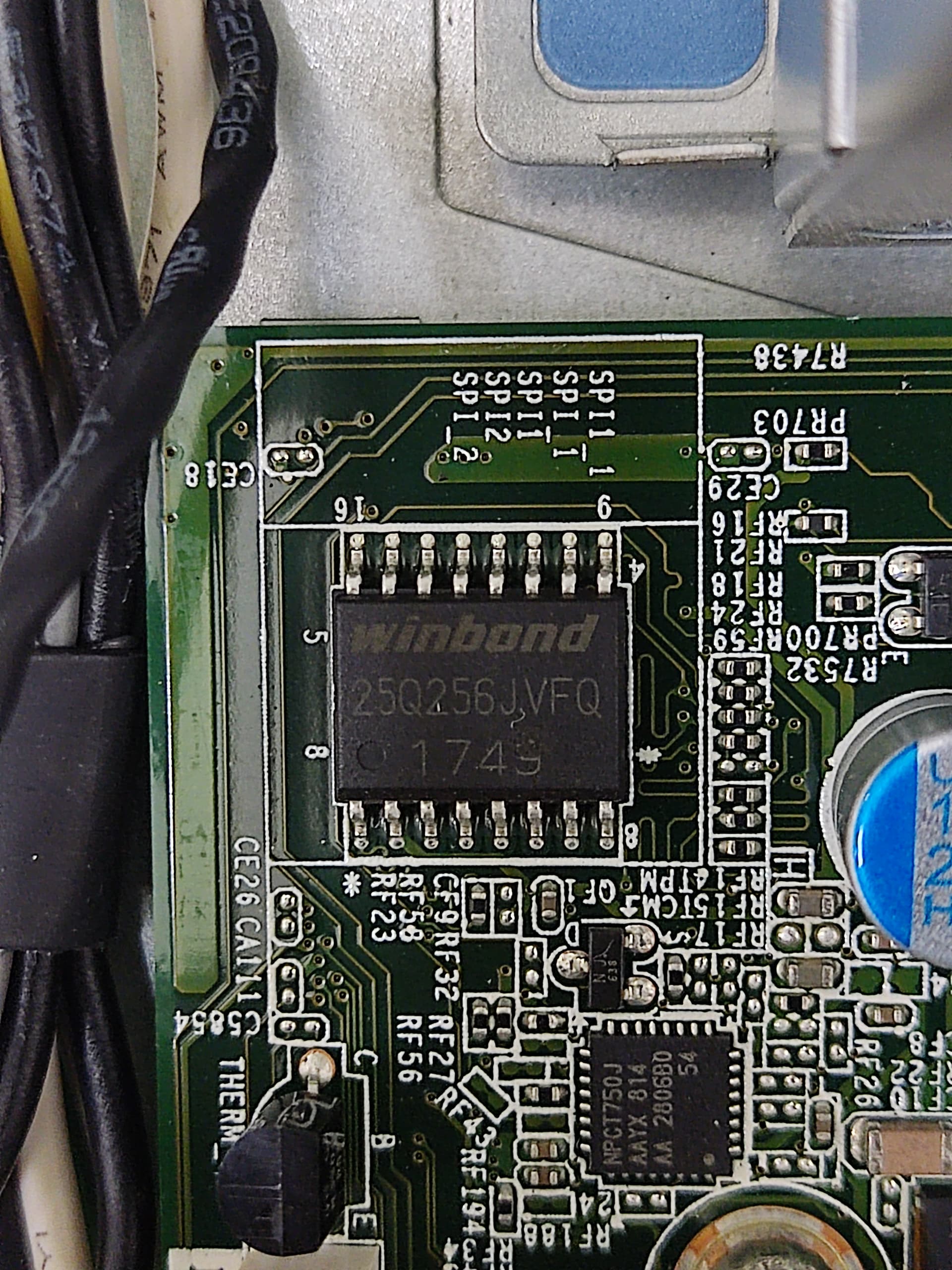
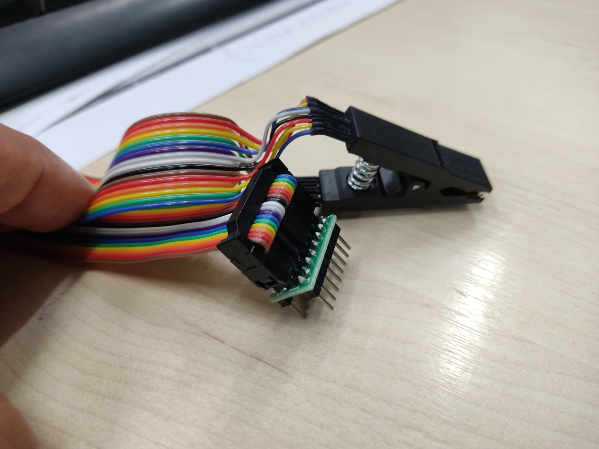
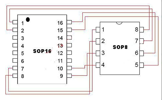
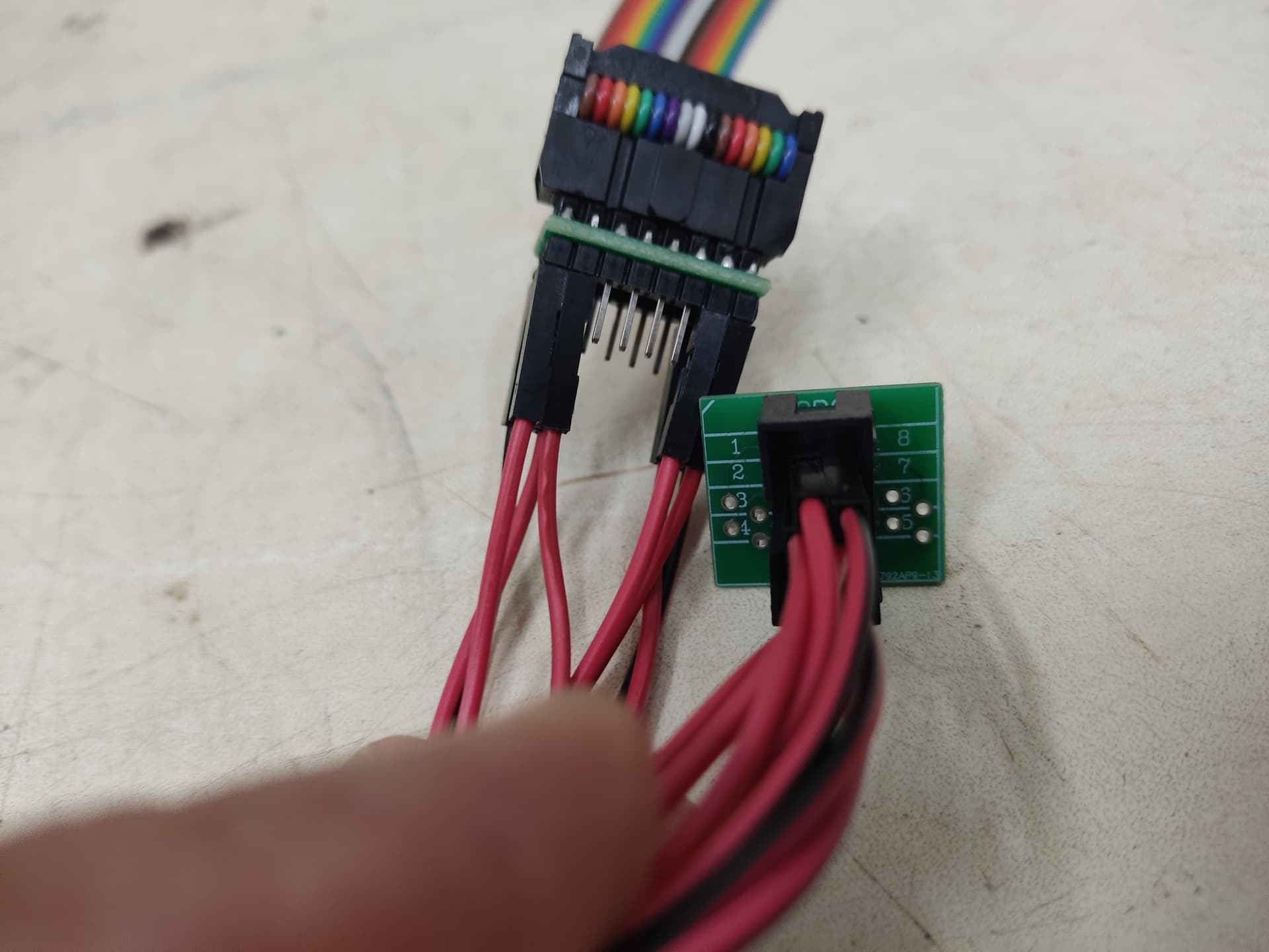
It all depends on the signals/wires assigned from the clip to the header and to the CH341 itself, any complains ask the chinese… now thats a full 16/16pin header, you need the check the Winbond W25Q256JV diagram of the SPI as usually the 8 midlle pins are not used.
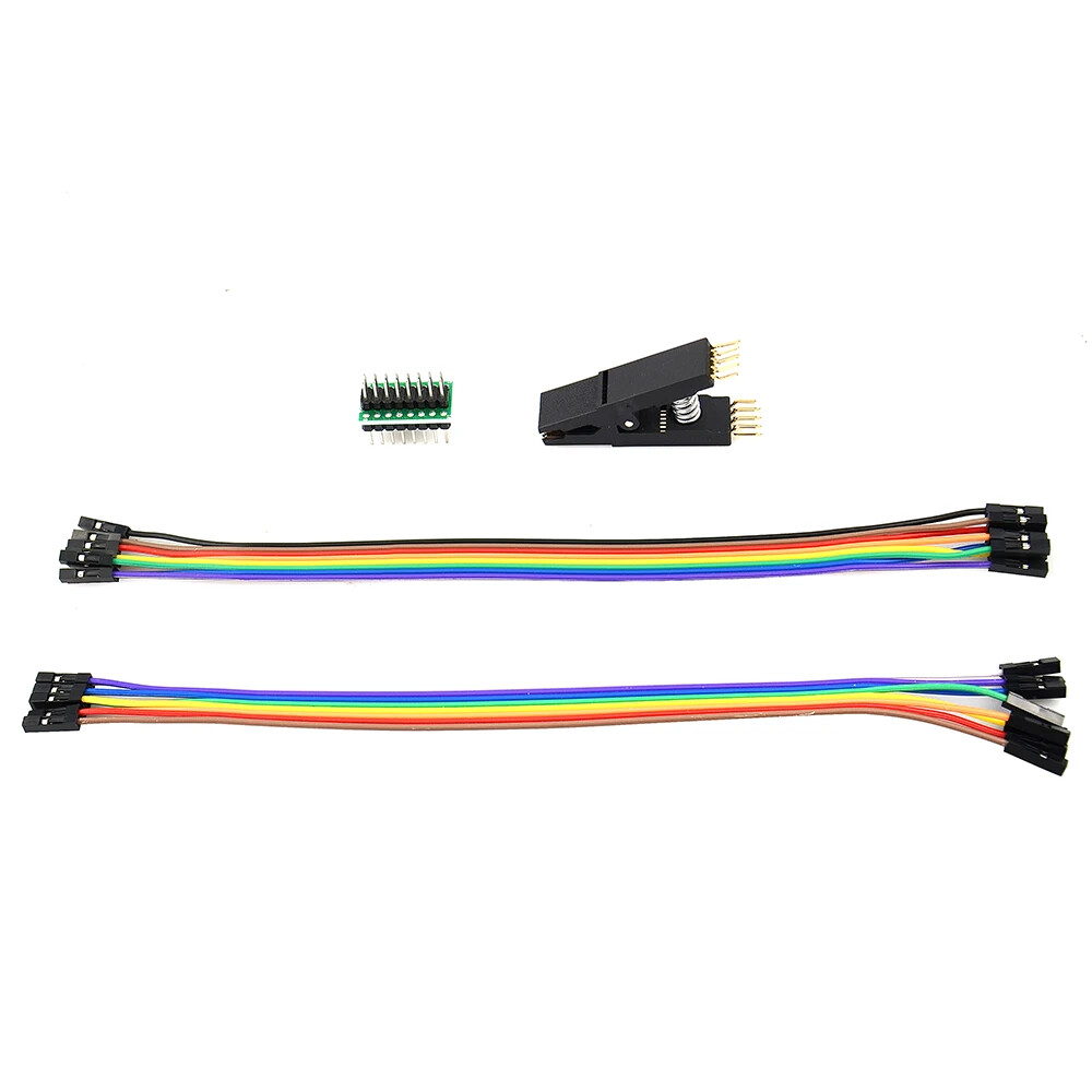
I have 8 to 16 header and Dupont jumper wires…not a full header block that you cant exchange pin/wire assignment… you may have to modify the something in clip (The needles) itself (You cant on the header) but you can also break the solder on the wires doing so…cheap stuff
It all depends on the signals/wires assigned from the clip to the header and to the CH341 itself, any complains ask the chinese… now thats a full 16/16pin header, you need the check the Winbond W25Q256JV diagram of the SPI as usually the 8 midlle pins are not used.
I have 8 to 16 header and Dupont jumper wires…not a full header block that you cant exchange pin/wire assignment… you may have to modify the something in clip (The needles) itself (You cant on the header) but you can also break the solder on the wires doing so…cheap stuff
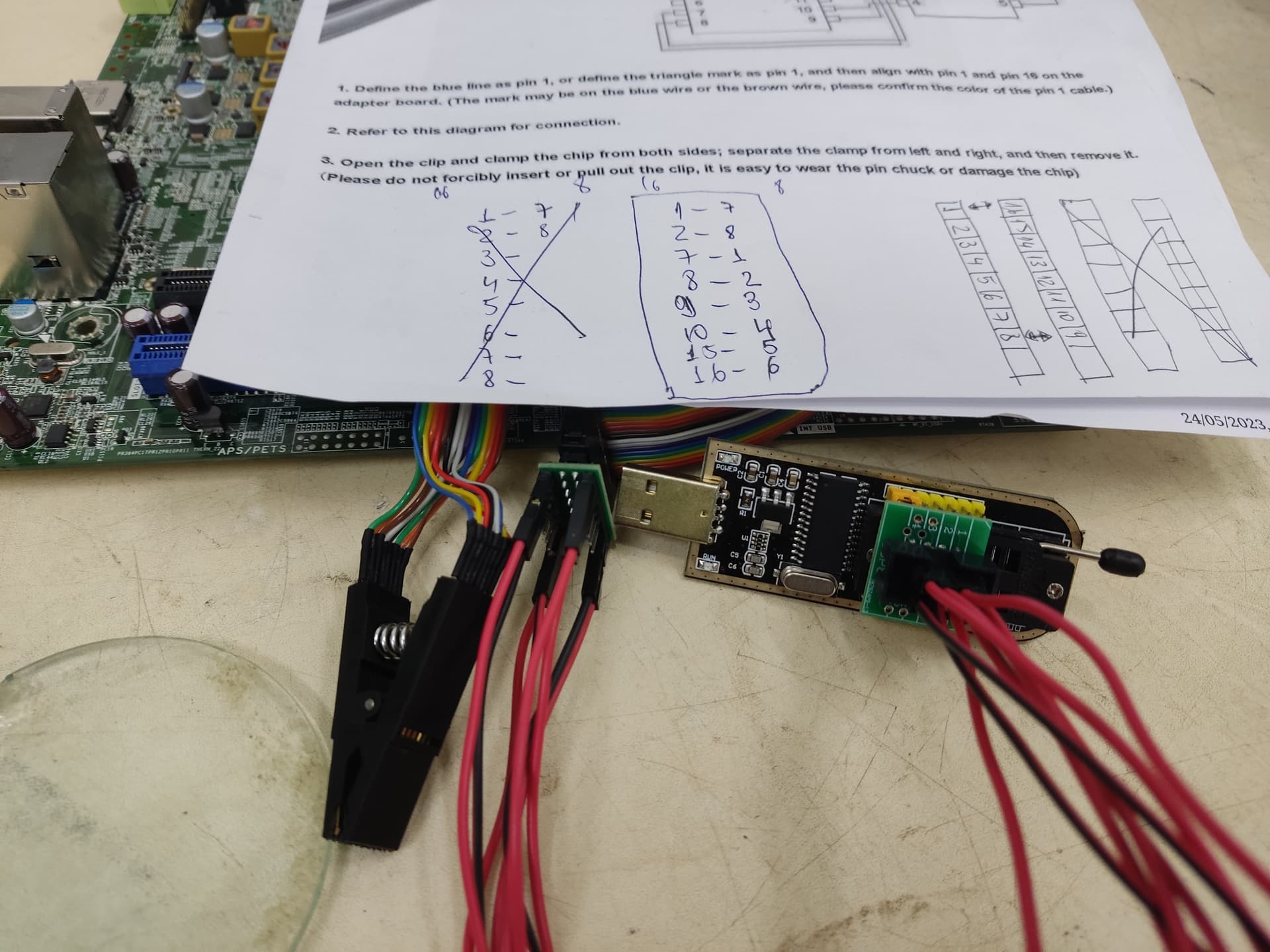
This is not my picture, its an illustration to show you a conversion from 16 to 8pins to plug on CH341, theres several blank pcbs to build one, example
If not using the info and connection as made by that user in the thread i linked before, basically we need something like this, but the model of the SPi IC has something to say, these are not easy ICs to flash and we do not achieve great percentage of success compared to SOIC8…
You better get in some Brazilian forums to communicate better on this details…