I have 2 Dell M4400 laptops. They came with AMT “disabled” from the factory. Yet in HWinfo it says AMT is supported and so is its out of band lan connection.
Started by downloading the latest released bios and attempted editing with phoenix tool 2.66. The bios breaks into the sections nicely but recompiling even an untouched version fails with “HDR checksum error”.
Running demefactory from https://libreboot.org/docs/hcl/gm45_remove_me.html on the dumped rom produces a garbage header file with mostly FFs.
Either way, it seems that the packed bios EXE will only flash HDR files in a GZip from what I’ve read.
Flashrom in linux won’t work. Winphlash won’t either.
I ran MEA on the firmware and this is what I get.
1
2
3
4
5
6
7
8
9
10
11
12
13
File:     Original-M4400A29.hdr

Family:   ME
Version:  4.2.60.1060
Release:  Production
Type:     Update
FD:       Unlocked
SKU:      AMT
Date:     26/06/2012
Platform: Mobile
Latest:   Yes
Since I have 2 and one is rather sacrificial. Ultimately it would be cool to play with AMT on one but secure the other. At minimum do the header mod for a spy-free bios and then load "functioning" ME into the other. Best case scenario I'd like to be able to remove modules from the bios images (ie, me, computrace, TPM?) and inject a slic as well.
There is so much information here that I'm a bit overwhelmed. Any help would be appreciated.
@NSAfarm :
Welcome at Win-RAID Forum!
Since I am not an expert regarding BIOS modding of Dell computers, I am not able to help you myself, but I hope, that you will get support by somebody else.
Tip: After having entered the words "Dell Precision" or "Dell BIOS modding" into the search box, you will get hints to other threads, which may be interesting for you.
Good luck!
Dieter (alias Fernando)
You need to work on your system’s SPI dump and not deal with Dell’s executable or HDR file. If you can dump the full contents of the SPI chip then you can easily do whatever you want, including disabling the ME via ich9deblob or similar.
I’ve been trying to avoid buying an external flasher. Was going to try the Intel AMT/ME tools for the correct version (4). Hopefully I don’t misread that they do some sort of SPI dump. I’m slowly going through the 100s of posts here and on MDL.
Yes, Flash Programming Tool (FPT) v4 which can be found at the ME thread. Or flashrom under Linux if that’s your thing. Try if you can dump with these but if the Flash Descriptor is locked and does not allow read/write access to the ME region, you’ll need an external flasher, soldering and so on.
I tried FPT v4 and it couldn’t load the driver (some dll). I assume its 32bit on a 64bit windows? FPT64 and tools from here: http://forum.notebookreview.com/threads/…bios-mod.788481
say the platform is not supported.
Flashrom really cries about being on a laptop and couldn’t identify the correct chip. I have a log from trying previously: http://pastebin.com/p8t9nzk4
Not sure if that log means its locked down.
edit: maybe something like this would work: http://imgur.com/a/oU4il
at that point I might as well get a programmer, will any of them work without desoldering the whole chip or pulling gnd/vcc off the board?
got it to read:
1
2
3
4
5
6
7
8
9
10
11
12
13
14
15
16
17
18
19
20
21
22
23
24
25
26
27
28
29
30
31
32
33
--------------------------------------------
Flash Programming Tool. Version 4.2.0.1017
Copyright (c) Intel Corporation. 2007-2009

Southbridge: ICH9-M
Reading file "fparts.txt" into memory...
Initializing SPI utilities
Reading HSFSTS register... Flash Descriptor: Valid

	--- Flash Devices Found ---
	MX25L3205A	ID:0xC22016	Size: 4096KB (32768Kb)

Using software sequencing.
Reading region information from flash descriptor.

	--- Flash Image Information --
	Signature: VALID
	Number of Flash Components: 1
		Component 1 - 4096KB (32768Kb)
	Regions:
		Descriptor - Base: 0x000000, Limit: 0x000FFF
		BIOS       - Base: 0x260000, Limit: 0x3FFFFF
		ME         - Base: 0x00B000, Limit: 0x25FFFF
		GbE        - Base: 0x001000, Limit: 0x002FFF
		PDR        - Base: 0x003000, Limit: 0x00AFFF
	Master Region Access:
		CPU/BIOS - ID: 0x0000, Read: 0x1B, Write: 0x1A
		ME       - ID: 0x0000, Read: 0x0D, Write: 0x0C
		GbE      - ID: 0x0218, Read: 0x08, Write: 0x08

Used Space: 4096KB, Actual Space: 4096KB
But flash desc + ME region is definitely locked. :(
Found the schematic:
http://kythuatphancung.vn/download/dell-...schematics.html
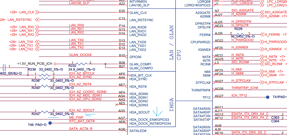
Pin A7 goes to? GND? VCC? It controls Intel HD Audio Dock Enable. Can it be shorted through the dock connector?
EDIT by Fernando: Put the code part into a “spoiler” (to save space)
The ME4 tools are old and may have problems running at newer Windows OS. The DOS version will always work though if you cannot get the former to work. If "FPT -d spi.bin" command shows CPU Access Error or similar then your FD is locked indeed. You have a pre 6-series system so you are not looking for SDA_HDO of the audio chip but rather for GPIO33.
According to that schematic there are 2 ME_FWP. The GPIO33 and GPIOK0. Can’t GPIOs be set low via software?
Making FPT work required taking the exe from the old v4 and adding the chip definitions from a new one. The SPI chip is 16pin according to my searching, most other laptops have SOIC8 varieties.
I tried sprom program from:http://forum.ixbt.com/print/0017/038124.html to set gpio33 but then the computer shuts down. So some manufacturer does it from software.
Sometimes they can but only if the OEM has such tools and got leaked etc. For your Dell system you’ll have to do it manually I guess. I see that GPIO33 is at the Audio chip (IDT 92HD71B7), which pin exactly not sure though.
According to that schematic the pin is not connected to the audio chip from the intel HDA.
From what I see the sprom.exe is supposed to set the gpio and then reboot, instead it shuts down. It is for version 6 of the ME so it never finds the engine. I opened it up in IDA and my chip is supported amazing enough. Maybe someone smarter can change the incorrect power command so it reboots or doesn’t do anything and you can ctrl-alt-delete
I’ve mirrored the schematic too in case it disappears.
Pin 15 of ECE5028 is me_fwp according to page 37. Also connected to R648/649. Does that look right?
SPROM.zip (13.4 KB)
23f96_LA-4051P_.pdf (1.15 MB)
Figured a bunch out. Putting phoenix tool in advanced mode by adding the INI generates the update files now. Upgrades/downgrades can be done using the recovery mode. It involves holding end while plugging power in and modelnumberVVV.hdr will flash regardless of version.
So now I can add slic and change out bios modules at will.
3E_39.ROM - Contains AMT bios interface for provisioning, etc.
3F_33.ROM - Contains computrace code but its rather small.
4B_37.ROM - Intel storage firmware (Intel(R) RAID for SATA - v8.0.0.1039)
I tried wiping the first 2 with 0s and no issues arise. Changing out the raid module:
>Intel MSM RAID ROM v8.9.1.1002 - “unsupported hardware”
>Intel RST RAID ROM v11.2.0.1527 - blinks and blinks, nothing happens
There are other fun strings in there related to ME fw update, overriding the flash descriptor and a menu similar to the computrace menu that lets you chose AMT/Noamt/NoSSL but would require actual cracking to work.
Why don’t the raid FWs work?
There is unlocked flash descriptor inside the hdr file. It must be used during flashing or something. I changed it and it; had no effect, the HDR file contains AMT firmware in the 2nd half.
I obtained an spi bios dump of the E6500 (same motherboard). The flash descriptor is in the same place and has the exact same layout. WTF Gives? It should be fully unlocked with these bits set.
E6500: mega.nz/#!I3BTQIja!KxFxixdH2uzsPBWLj9aXJGWgPqFJFauruZcrB_Rtnh0
In fact, E6400 has the same layout too.
Two things:
1) Do not try to mod the HDR or any custom Dell executable. The best and by far easiest and safest thing to do is to use a programmer (or software dumper like FPT/Flashrom if your FD is unlocked or Dell has a jumper/BIOS option to enable ME Reflash) and get the contents of the SPI chip directly. That way you can work with proper modding tools and proper/known file structures.
2) That dump you have uploaded is either corrupt or incomplete. Maybe that system has two SPI chips and this is the second? Even so, a big part in the begging is filled with zeroes which is not normal, something is wrong.
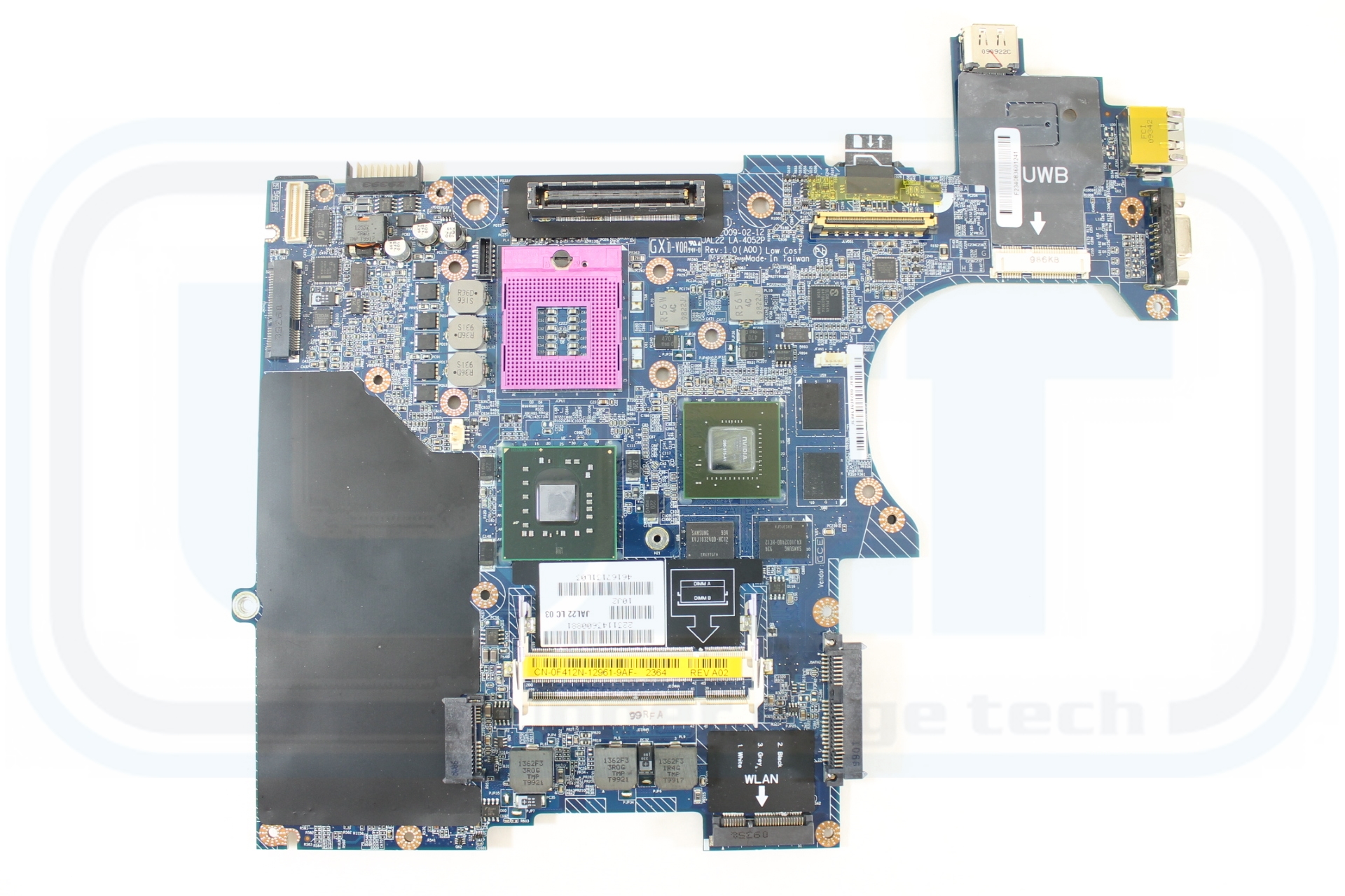
Which programmer though? I read your thread and the ICSP results weren’t stellar using the cheap one. The SOIC16 chip is detected by intel flashing tools but on board pictures I only see SOIC8.
bottom: s3.amazonaws.com/MOBO/MOBO-00405-1.JPG
top: s3.amazonaws.com/MOBO/MOBO-00405-2.JPG
Phoenixtool from MDL now makes the EXE but its easier to flash in recovery mode. It appears I cannot brick this way but neither can I modify the FD or ME region. If IDA matched the strings to where they are called, I could probably enable that flash descriptor override to stay on all the time.
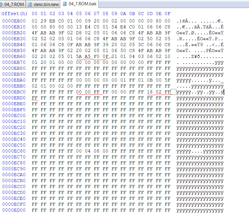
Its in here somewhere:
mega.nz/#!VqRkWZbB!qgY5SpOhCIHUS8xtvCwa2Nz3cWMKCQqYr7F7DJpGYZw
if you search “5A A5 F0 0F” it shows up.
When it comes to FD locks, what the downloadable SPI images or Dell’s hdr files say, does not matter. The locks cannot be overwritten by reflashing from software. The FD is read/write locked as well so you cannot change its access rights by any software means. You would need to first allow read/write access and then alter it. To allow read/write access you must either use the pinmod (GPIO33) or a hardware programmer on the chip itself. That way you can reflash the FD with unlocked read/write access, after which you can use FPT or Flashrom freely. The point is, you cannot unlock the FD by your current method of modding the .hdr because it won’t do you any good (unless the FD is temporarily unlocked as well during that “recovery mode” which I doubt).
As for which programmer you need, I don’t specialize in these things. You should be able to find the SPI chip quickly by FPT or Flashrom (try both) and especially at those board schematics you have found. Don’t trust what FPT says about 8 or 16 pins, those text databases you replaced the old ones with may be for different platform and thus it recognizes the wrong chip. Try flashrom to see what it reports but as I said, your best bet are the board schematics. If you have a SOIC8 chip, then I don’t see why a cheap CH341A programmer + clip wouldn’t be able to read and write the chip. Mind you, you will probably need to desolder and solder back the SPI chip to read and write to it, check that thread for more details.
Its the right series according to flashrom. So it is one of those MX chips. FPT just gives a specific chip both 4 and 8 pin versions are in the text. Fparts.txt is just a listing of flash chips and their parameters.
Its true that it could just be picking the first chip on the list since they all have the same ID.
MX25L3205A, 0xC22016, 0x2000000, 0x1000, 0x20, 64, 0
MX25L3205D, 0xC22016, 0x2000000, 0x1000, 0x20, 64, 0
MX25L3206E, 0xC22016, 0x2000000, 0x1000, 0x20, 64, 0
MX25L3273E, 0xC22016, 0x2000000, 0x1000, 0x20, 64, 0
MX25L3275E, 0xC22016, 0x2000000, 0x1000, 0x20, 64, 0
Its pretty clear to me from reading several similar bios that dell updates the ME region by temporarily jumping to that in-rom flash descriptor and using it while updating. Even if the real table is still locked, the ME region will not be and the table is remapped. I can test by r/w locking the table and trying to flash to see if it fails. Otherwise you could never update the ME firmware.
That’s the rub, I don’t want to disassemble and solder on the good laptop.So a better programmer with more 3.3v makes me want to skip the cheap programmer.
So my programmer came.
Bad news though, the chip needs to be desoldered from the board. In neither ICSP nor regular programming will it read or identify. I tried powering it with the board and that didn’t work either. I know the programmer can do it because I tried on other chips.
It is really MX25L3205D and looks like the other dell dumps.
Dump:
https://mega.nz/#!JmZzkZYT!kxHpIBjOhw7Xi…UDqd7Y-V3eNrDlU
The location is at the top of the board near the right mouse button for the nub. The palmrest and the screen must be removed. But the board can be left inside.
Since it took desoldering to unlock the FD I want to keep it unlocked.
Will manufacturer or crisis bios recovery lock it? Changing Me/AMT fw? Provisioning it once its enabled? Flashing with ME region deleted (00 00 00 00) in the FD?
If the FD is unlocked and a new SPI image is flashed with the FD locked, it will end up locked again. The opposite does not apply of course. Another way to lock it is via Flash Programming Tool (-closemnf or similar). Flashing only the ME region, provisioning it etc won’t change anything at the FD access control. Basically you need to be careful not to flash any SPI image which has the FD locked (ME Analyzer can quickly let you know by the way, or UEFITool) and to make sure there is no FPT parameter which closes manufacturing mode in case you or the OEM uses it for servicing.
For some reason FPT says the bios region is locked even though all locks are FF just like factory mode.
I can backup the SPI image but I can’t flash spi or bios region via FPT. ME flashes ok.
SPI dump crashes v4 Flash Image tool but not v5. So I can make an XML with v5 and load it in v4.
Original image really has ME region of almost all FF.
I tried flashing 4.2.0.1020_AMT_PRD_EXTR.bin and 4.2.10.1023_AMT_PRD_RGN.bin but nothing seems different. I put the option rom back in the bios but still can’t access it.
Added my descriptor which I can flash/dump with FPT still.
DESC.zip (296 Bytes)