Considering the chip it is, should flash descriptors be unlocked prior to either read or write?
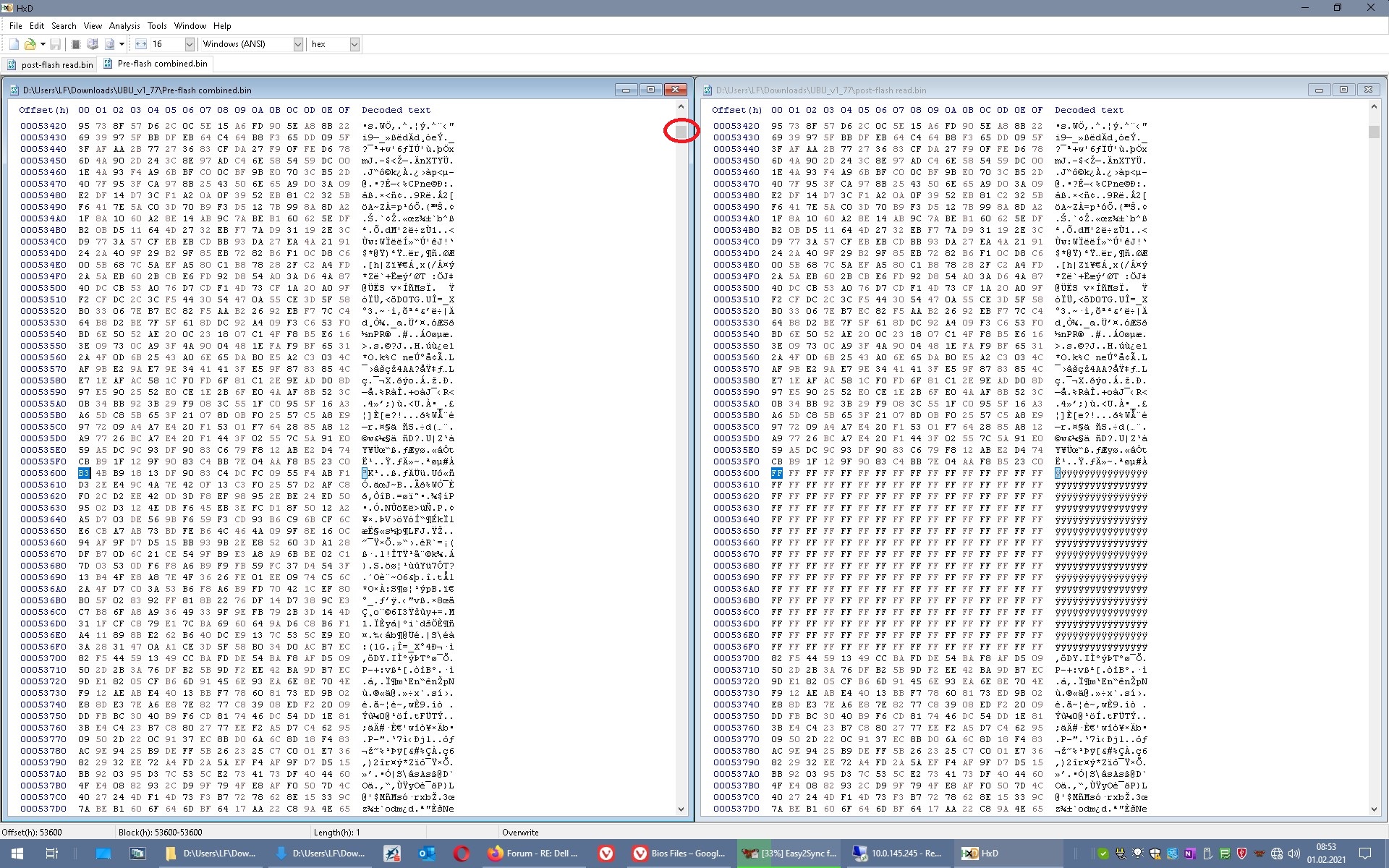
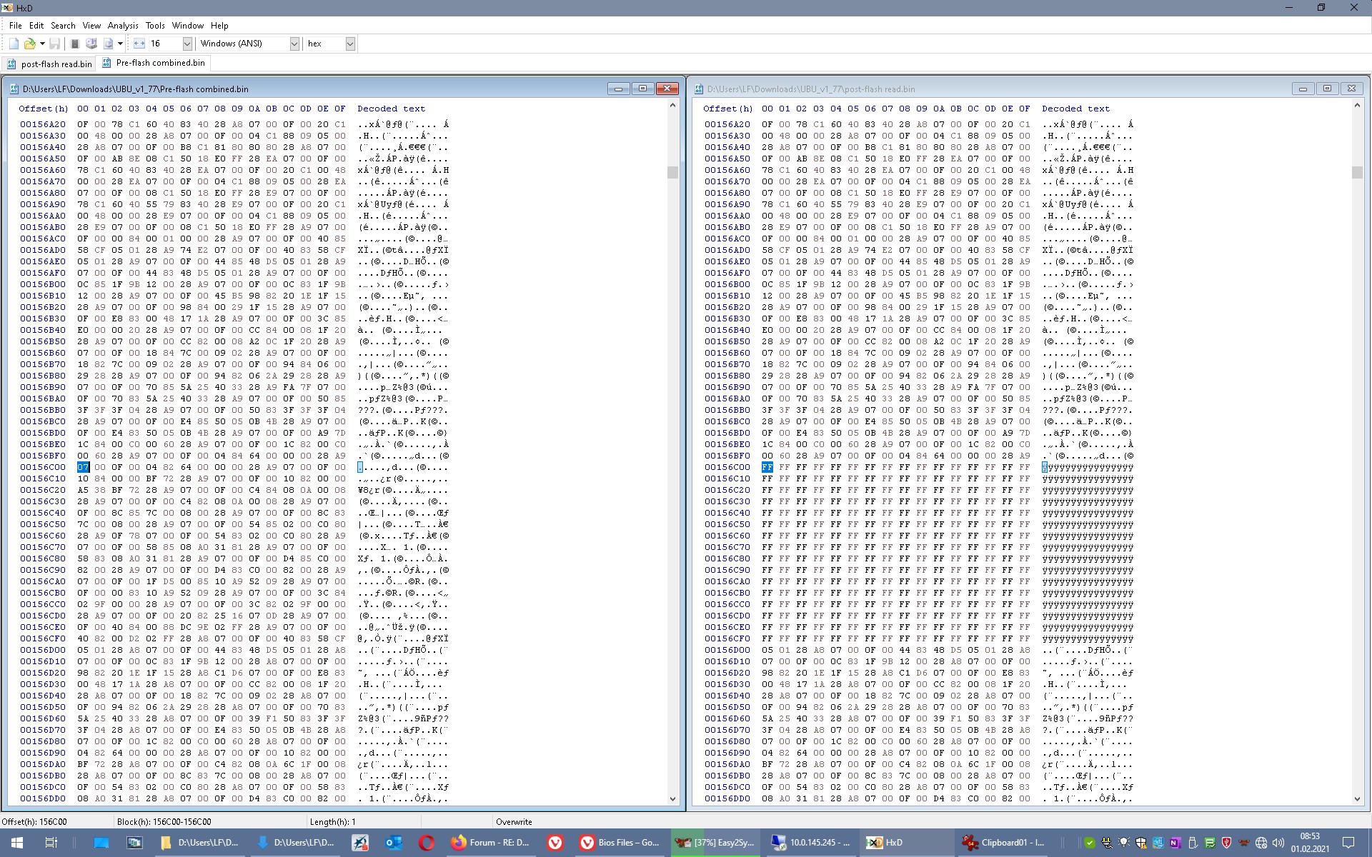
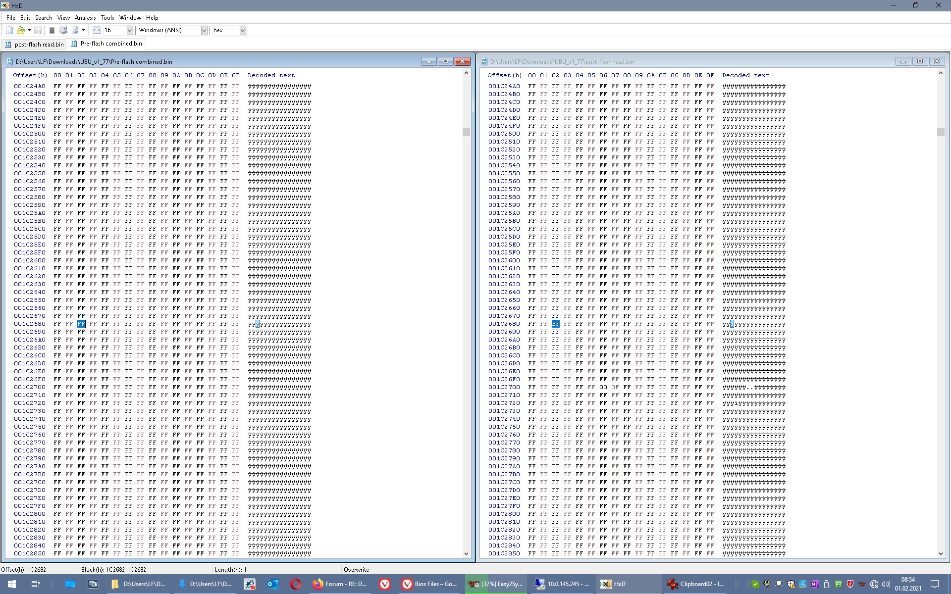
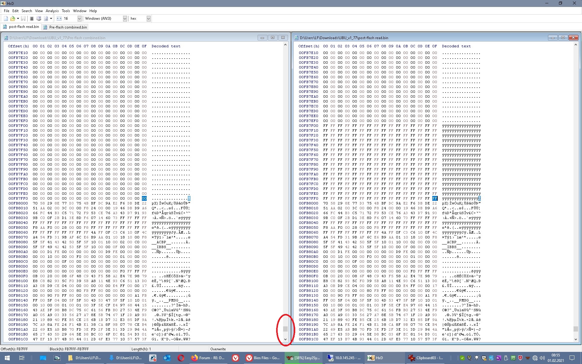
Got files combined, flashed new .bin and compared the read I got from that in HxD. Files are almost identical but at offset 0001C800 down to 0001C8F0 they do not match, in fact the HEX values on the read I got from the chip after programming it just show as FF’s. Have gotten same exact results across multiple reads. Have not tried booting up. However, I don’t have my cmos battery plugged in and I’m wondering if that could be why. What do you think? Attached are the combined file I made from the two you sent me and the file I got from the read after flashing it. Files are labeled pre-flash and post-flash (same link as earlier)
Drive link: https://drive.google.com/drive/folders/1…CmwLimEpHS4pxlZ
edit: sorry making multiple posts, will make sure to edit posts with new information as I get it from now on
Edit: verify also fails, again not sure if battery has anything to do with it or if that’s irrelevant. Tried unlocking flash descriptors in asprogrsmmer but then after erasing, writing, reading and verifying the dump is even worse. I don’t understand, asprogrsmmer 1.41 is supposed to be able to read and write properly on this chip, I’ve even seen evidence in other posts of it working. Not sure if it’s just user error and I’m not properly disabling or enabling flash descriptors or something else
Combined file is OK. Please zip files, this way one has at least a check that the content is unchanged.
That’s a bad read from start to end, see pictures in spoiler. You got complete blocks not written, but also flipped single words.
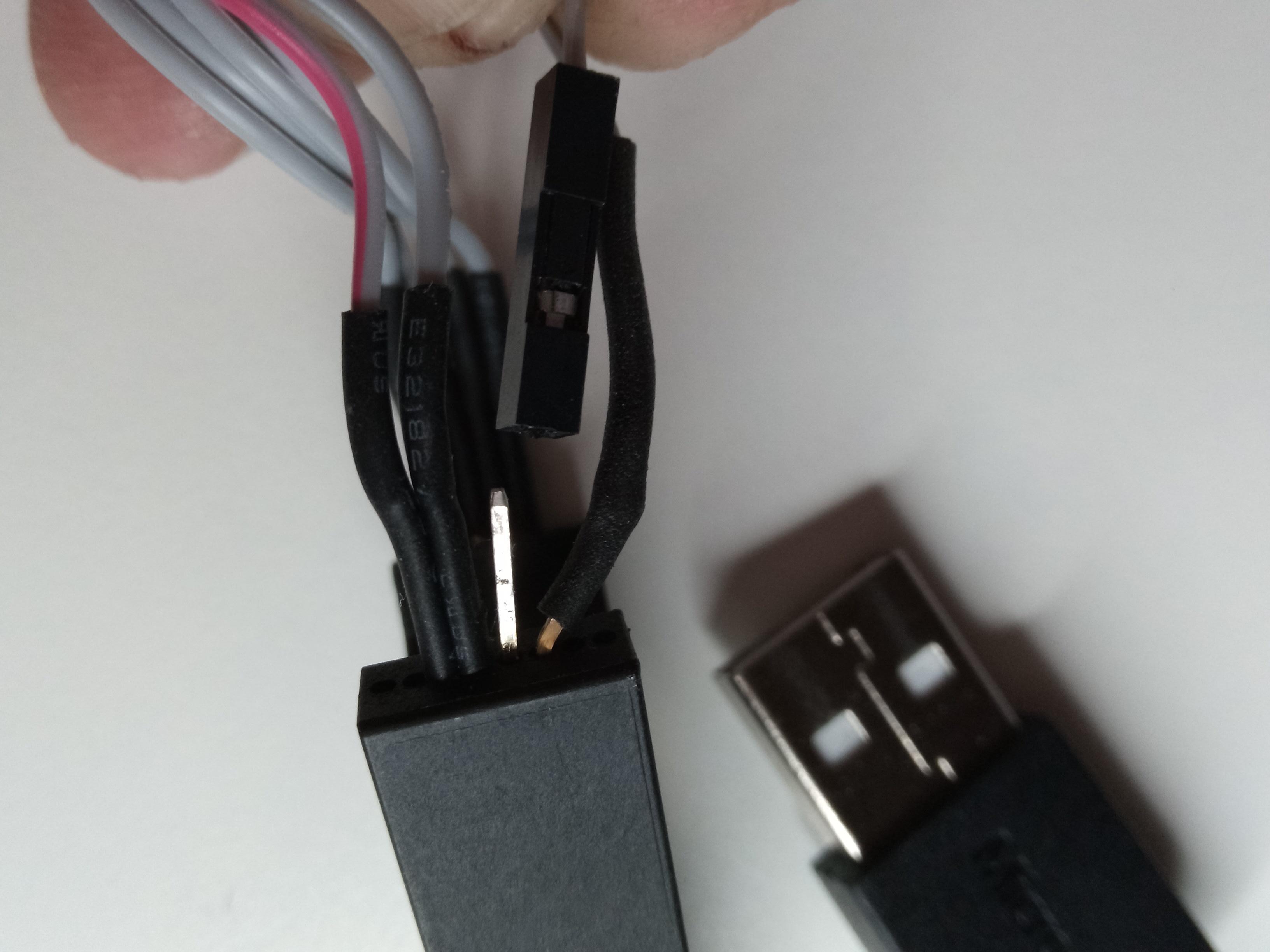
Most often it's the seating of the clip (the connection of the contacts meant, not the orientation!), rarely voltage/ high current drawn, somtime incompatible program (but you said you checked that and it would be more a pattern like 'every n-th block not written'...) Are the LEDs on the CH341 behaving as expected? First on when connected, second on when working?
Try to find other threads with this Dell and use of CH341, see what they did, or if they reported problems?
Flash descriptor is without meaning when flashing with programmer. It's quite useless to fine- tune things in the image before we know how to flash it securely.
EDIT You use Asprogrammer 1.41, right?
Good idea, will zip from now on. Yeah using asprogrsmmer 1.41, some posts said colobri works. I can’t help but think I’m overlooking something simple. Like you said, it could possibly be a bad connection. I’m using a Pomona clip, really good as far as test clips go and I’ve tried re-clipping a few times with same results. The ch341a came with one of the cheaper test clips which I didn’t use since I had one already. When I ordered the clip I made sure to get 2 just in case(Pomona’s). I’ll try using the other clip and replacing all of the jumper cables connected to it.
Edit: yeah, light is on verifying connection (bright not dim) and activity light turns on when in use. Do you think it could be a driver error? I know this is grasping at straws and without you having it in front of you it’s hard to say for sure. Also for context, I have main battery and cmos battery disconnected, so maybe a voltage issue? I just didn’t want to fry the chip but now I’m worried the bios is simply perma-bricked
Edit: oh, sorry I overlooked your response on voltage. If it were the wrong voltage would we be getting different results than what we’re seeing?
Edit: default ch341a software sees it as being W25Q128BV, however writing on chip shows FV. I assume this is just an error as it doesn’t recognize it but maybe I should try it as that model instead
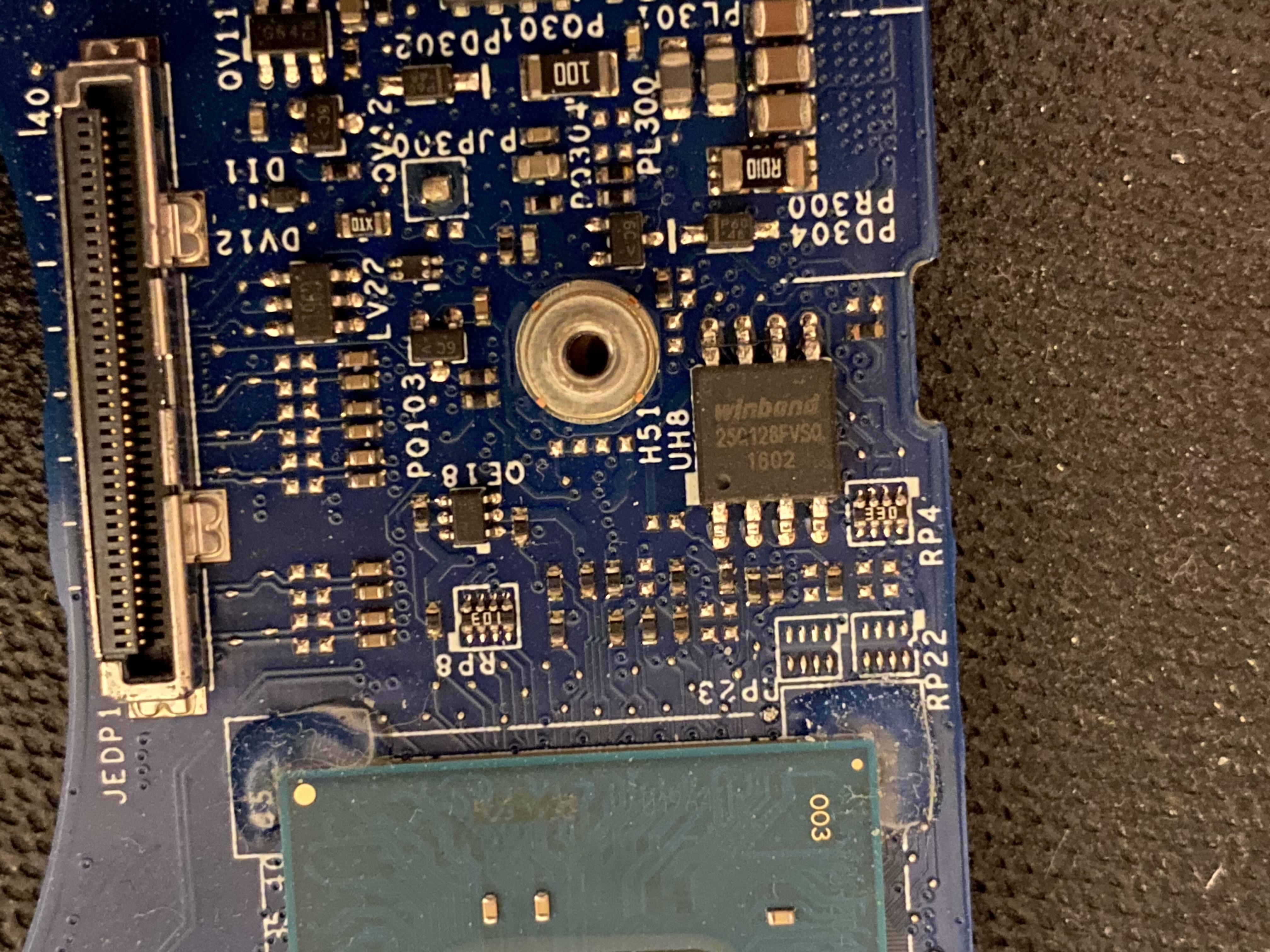
Can you make a sharp picture of the chip on the board in high resolution?
Otherwise I’d stay with ASprogrammer 1.41 and selected the correct chip (FV) from the list.
I can’t think of a driver error.
To get a fix on this: Just try to read the chip and get two or three reads that are identical. If you got two, three consecutive a 100% identical reads by ASprogrammer 1.41 try 1.18 version CH341A- if this read still is identical, too, you should have a good connected clip and try writing with ASprogrammer again.
Do it manually: Erase, Blank check (one down in “=”), Write, Verify, Read again, save to new file
Yeah, here’s a pic I took a couple of days ago. Am not with the laptop right now but will give that a go
Voltage- not wrong voltage, it’s a 3V chip, but voltage drop since there are other chips on the 3V line that normally would feed the SPI. Those chips may draw too much current from the programmer, so that the voltage could drop below ~2.7V. But the CH341 will in hard cases normally shut down, disappear from programming software (“not connected”) and LED 1 will be off.
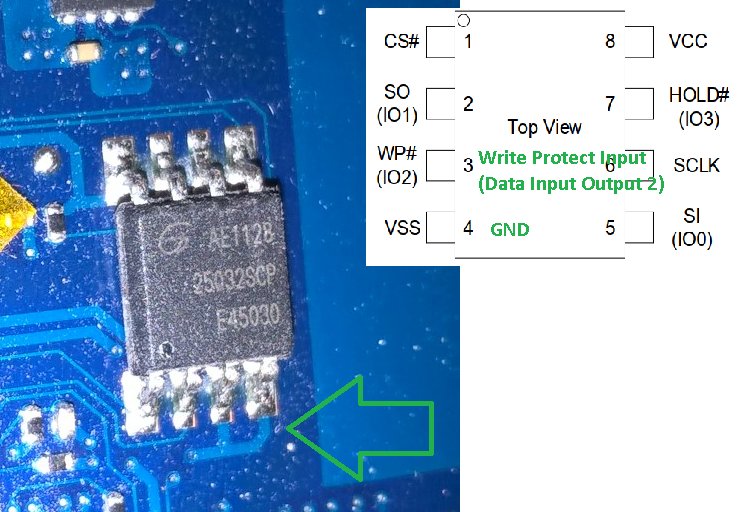
But you might check the 3V on pin 8 if you have a multimeter…
https://www.winbond.com/resource-files/w…32016%20kms.pdf
Ok, I just realized I’m an idiot. Remember how I said the activity light is on when in use, bright not dim? That is true, but only while the programmer software is actively reading/writing. HOWEVER, when I first hook the clip up to the chip, at first the activity light is on, then dims and strobes a little bit before finally shutting off. Windows then gives the usb disconnected sound which I didn’t realize before because I had my speakers muted. I think it may be a voltage issue, considering what you said about it shutting down, however the power light on the programmer stays solid red the whole time. Does that sound like I need to supply power to the motherboard to you? I spent almost 45 minutes making sure the clip was properly seated and got the same results every time. If I do need to supply power to the motherboard, should the main battery be enough or should I plug it in too or is there anyway to know for sure without just trying?
Connect chip, check 3V line with multimeter- does the voltage drop?
And you possibly don’t need all pins, I could cut out pins 3, 4 and 7 without anything happening on a 25Q128FV, might be worth trying if this will help already?
[GUIDE] The Beginners Guide to Using a CH341A SPI Programmer/Flasher (With Pictures!) (4)
From [GUIDE] The Beginners Guide to Using a CH341A SPI Programmer/Flasher (With Pictures!) (3)
Other recommendations/ reports are to put in CMOS battery (actually I never removed it) or/ and have the battery connected and/ or having even the machine switched on. These measures makes shortings more dangerous, so I'd recommend to put first the clip on and then adding a power source!
Some people added a capacitor to the 3V line to stabilize the voltage...
Hmm, still no luck. I have clipped and reclipped so, so many times. With the battery connected, battery and power supply connected, only power supply connected, no dice. In fact, when I add any power at all, the run light is totally off and ch341a software cannot even detect the chip. At this point I am going to try ordering a couple of new chips and dip8 programmer so I can do this with no interference, then solder it to the board. It’s the only thing I can think of working at this point. Lost_n_bios didn’t seem to think I bricked the chip beyond flashing, but I’m starting to think I must have. That or there’s just too much interference with the clip/not a solid enough connection
I have a question about unlocking the flash descriptors though, if flashing the bios image back onto the bios chip, will they automatically re-lock because the image says they should be locked, or will I have to re-lock if I’ve ever unlocked them at any point, regardless of whether or not I flashed an image where the descriptors are supposed to be locked?
Will them being unlocked make intel boot guard angry and force the computer to turn off after 30 minutes?
In asprogrsmmer, when I select the drop-down next to unprotected, what should I edit the values to in order to make sure the proper ones are locked again?
If I desolder the chips and connect it to the adapter, would I need a 3.3v adapter? Does this chip even require one? I’m so confused as to when one of those adapters are and are not needed.
Lastly, does the software know how to properly unlock the flash descriptors based on the chip chosen or do I need to manually edit Sreg to stay on the safe side like when locking them
Another option would be a bad CH341, those are very cheap items, I have now about 3 different programmers, most do work, but one decided first after som tries to work properly, so I would never trust them too much… Maybe all your trouble is a defective CH341?
Flash descriptor will not be changed if you don’t flash a bios including a new descriptor, or would use fpt(w(64)) --CLOSEMNF, what should reset FD to default values. But I’m not sure if it will be done if ME was no longer in maunfacturing mode already. FD will most often not be overwritten by a stock bios update, many of these bios update files do have unlocked FD.
Boot Guard should not be influenced by that, but Bootguard would anyway mean that there are restrictions for flashing/ changing the bios region. So unlocking FD would give you access to ME, FD, GbE(?).
No idea what correct values are for locking a chip again. If there’s a lock that can be programmed so easily, and the chipset itself knows how to open (and lock?) it again…
I never used a 3V adapter, you’d need a SOIC adapter. Option would be 3V mod described often, never did that.
nice!
thanks!
useful info!