If you’re worried about flashing your motherboard with an SPI Programmer, then this is the guide for you. Each step is explained in detail, with pictures. We’ll go over everything, from buying your Programmer to flashing your chip with Flashrom.
As per usual, this is a tutorial on the internet. Do anything you see here at your own risk. I am not responsible if anything goes wrong.
This tutorial couldn’t have been possible without:
Fernando, for the Win-Raid Forum,
ProIIIu3Hb, for their PIII Discord server,
dsanke, for being a BIOS modding god,
Droidbot and ylp1194045441, for helping me with the guide,
CodeRush for their original tutorial, and
deftdawg, for their original tutorial.
Part Zero: Equipment Required
1. CH341A SPI Programmer with SOIC8 Test Clip
2. Linux computer with Flashrom installed OR a Live USB with Linux
Part One: Buying
This is the easiest part of the guide ![]() (but that doesn’t mean the rest is hard!)
(but that doesn’t mean the rest is hard!)
All you have to do is buy a kit like this:
https://www.ebay.com/itm/EEPROM-BIOS-USB…er/192742554355
It has everything you need, from the Programmer itself, a 1.8v adapter (for AMD AM4 motherboards - more on that later), the SOIC8 Test Clip, and a bunch of other parts you might find useful later.
Part Two: Linux
If you are trying to flash your board with an SPI, there’s a good chance you already know the basics of Linux. Even if you don’t, though, I’ll still go over it.
Since the Windows tool has severe issues with some chips and doesn’t have an auto-verification system, your best bet is to do the flash from a Linux computer. If you don’t have one, you can use the instructions in the following paragraphs to set up a Live USB with Linux (a Live USB is one which contains an OS you can boot from and use as a normal computer). If you do have a Linux system already, you can skip to the next part of the guide.
First, download a Linux ISO. A distribution like Linux Mint XFCE is what I would recommend for a newcomer. You can grab the latest version (19.1) from here:
https://linuxmint.com/edition.php?id=265
Then, download the Universal USB Installer tool from here:
https://www.pendrivelinux.com/universal-…-easy-as-1-2-3/
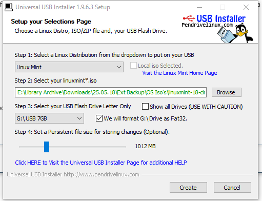
Next, plug in a USB of at least 8GB and load your ISO into UUI. Make sure you select the right drive, ISO image, and Distribution. Remember to check the box to format the drive, and select about 1GB of persistence space. When you are done, it should look like this:
Once your USB has been created, you are ready for the next section.
Part Three: The Flash
Before we do anything, we need to install a cool piece of software called Flashrom. It will allow us to program our BIOS chip with minimal issues. Fire up your Linux computer or your Live USB, connect your CH341A, open up the Terminal from the menu, and run the following command:
sudo apt-get install flashrom
Next, you need to figure out if your BIOS chip is socketed, or soldered. If you have a very cheap motherboard, a laptop, a graphics card, or a 200-series motherboard or newer, you will most likely have a soldered BIOS chip.
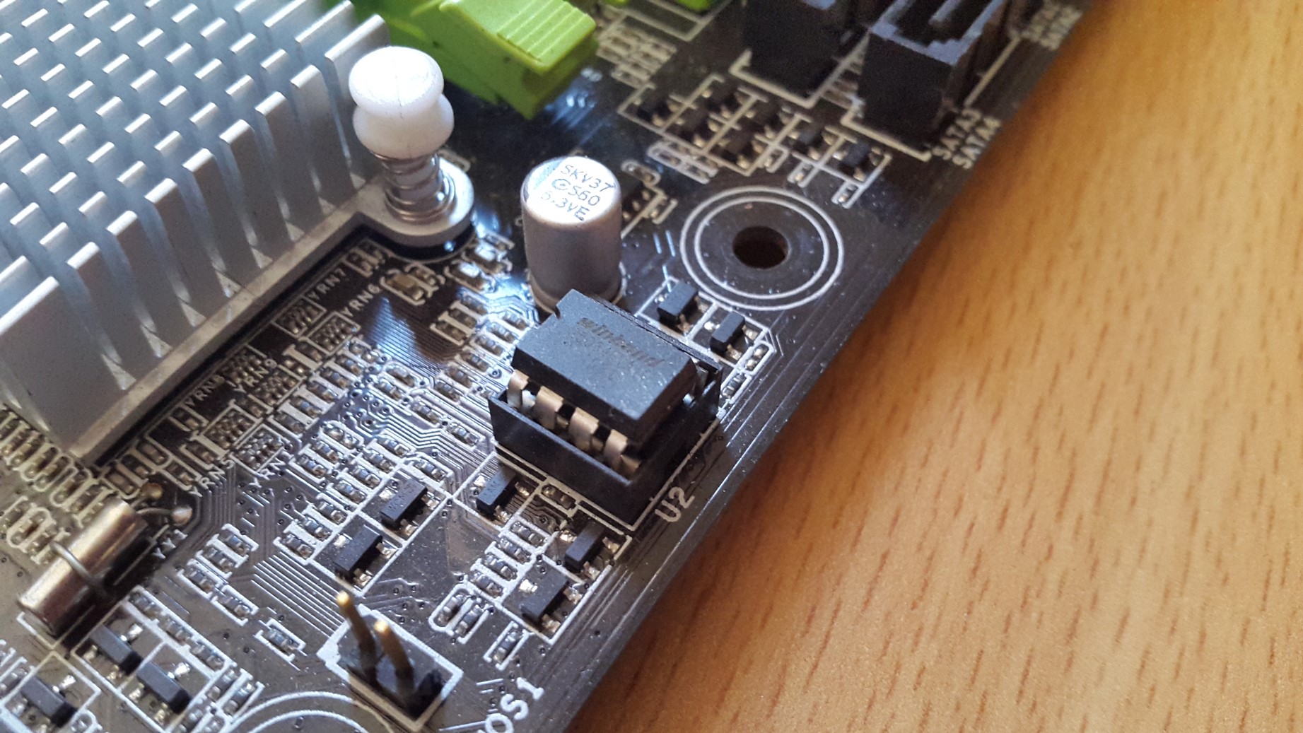
This is what a socketed chip looks like:
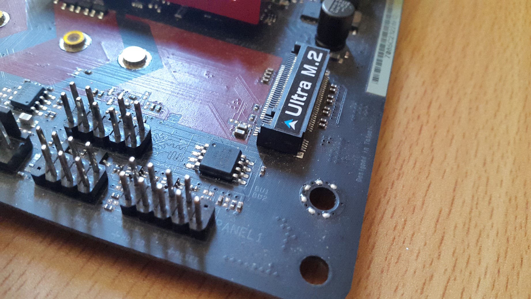
This is what a soldered chip looks like:
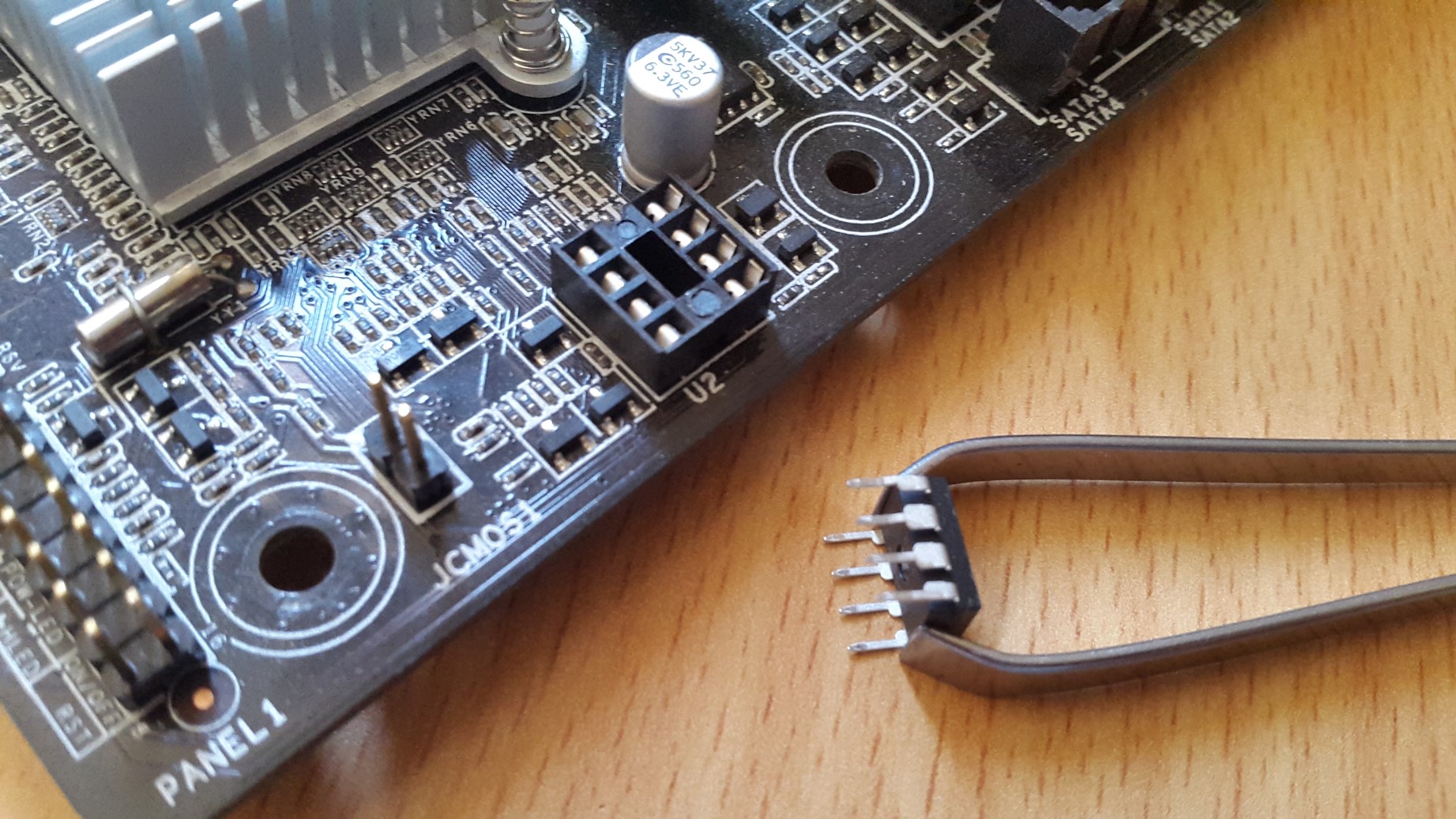
If your motherboard’s BIOS chip is socketed, you’re in luck! You can get away with using the CH341A on its own. You need to remove the chip first, like so (tweezers work):
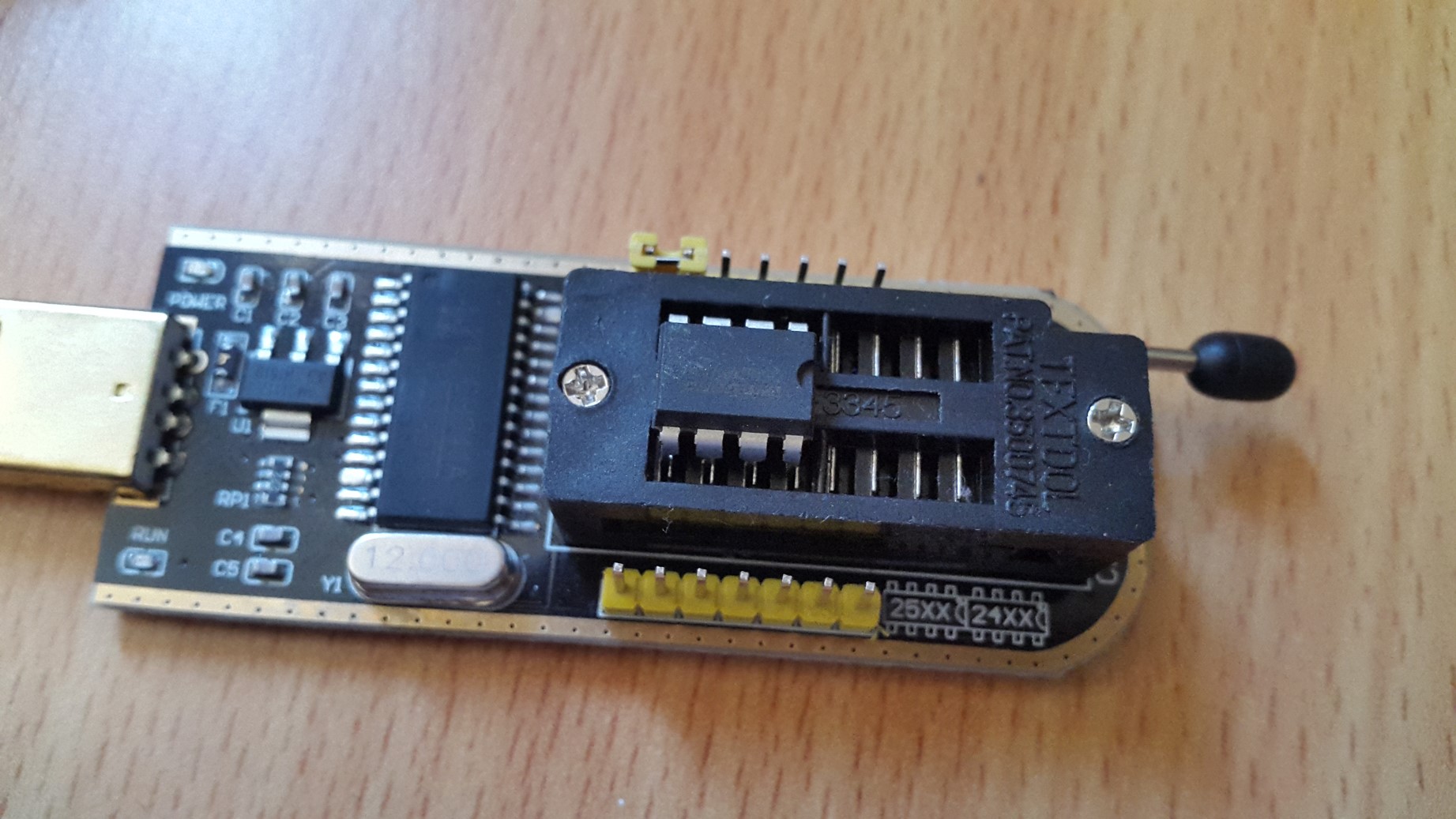
Then you need to install it in the Programmer, making sure the notch faces the same way as indicated in the white diagram in the bottom right corner:
If you have a soldered BIOS chip, the process is a little different. Instead of installing your BIOS chip into the programmer, you need to attach the plug end of the SOIC8 clip onto the small green part of your kit with the yellow pins sticking out. You need to make sure the red wire is corresponding to the pin numbered ‘1’. Then, you need to insert that assembly into the the CH341A. For this, the white dot in the small diagram should match the ‘1’ pin. When you are done, your now clip-ified Programmer should look like this:
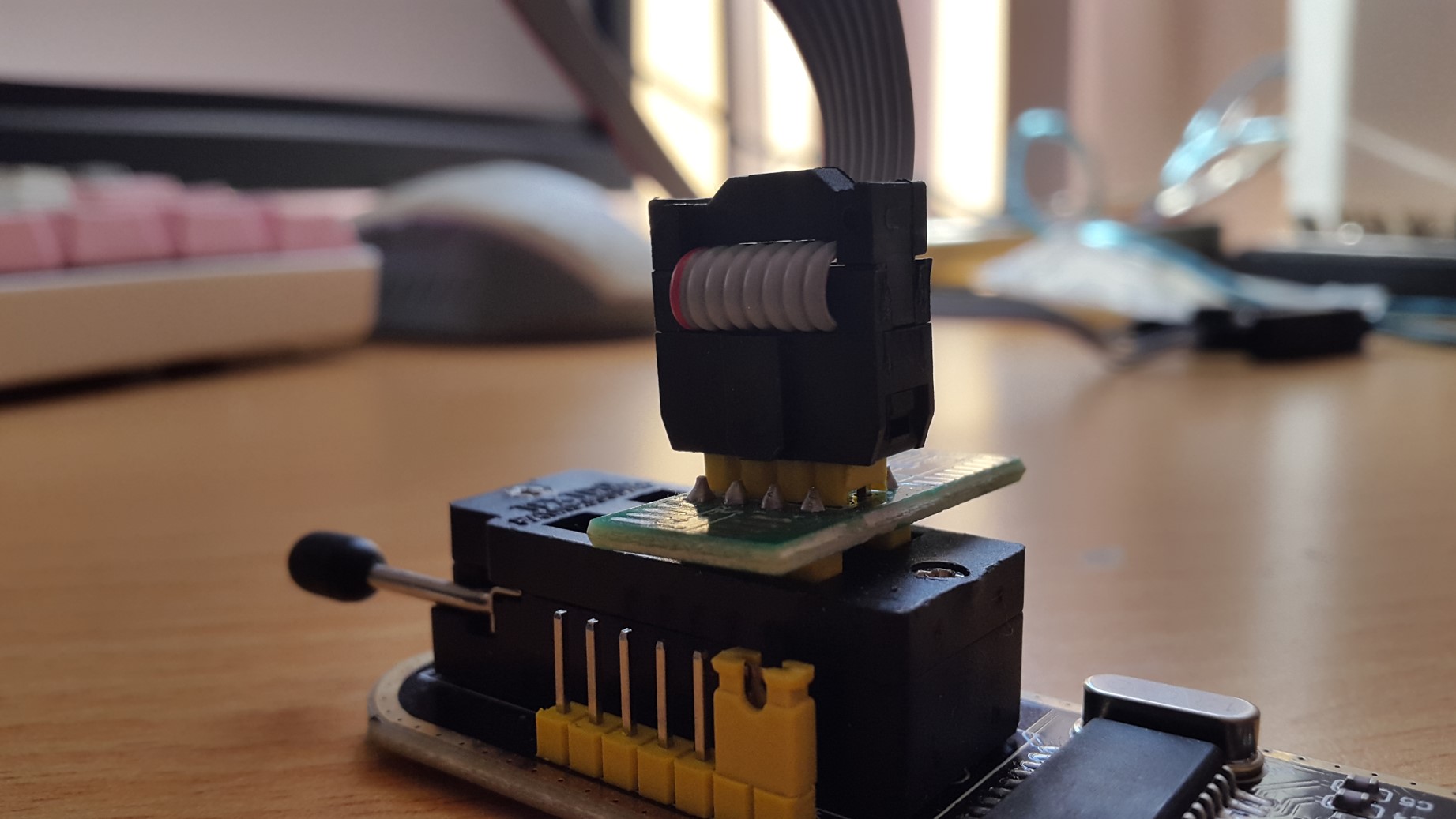
Note: If you are flashing an AMD motherboard, you need to put the 1.8V adapter into the SPI, and then put the clip assembly onto that.
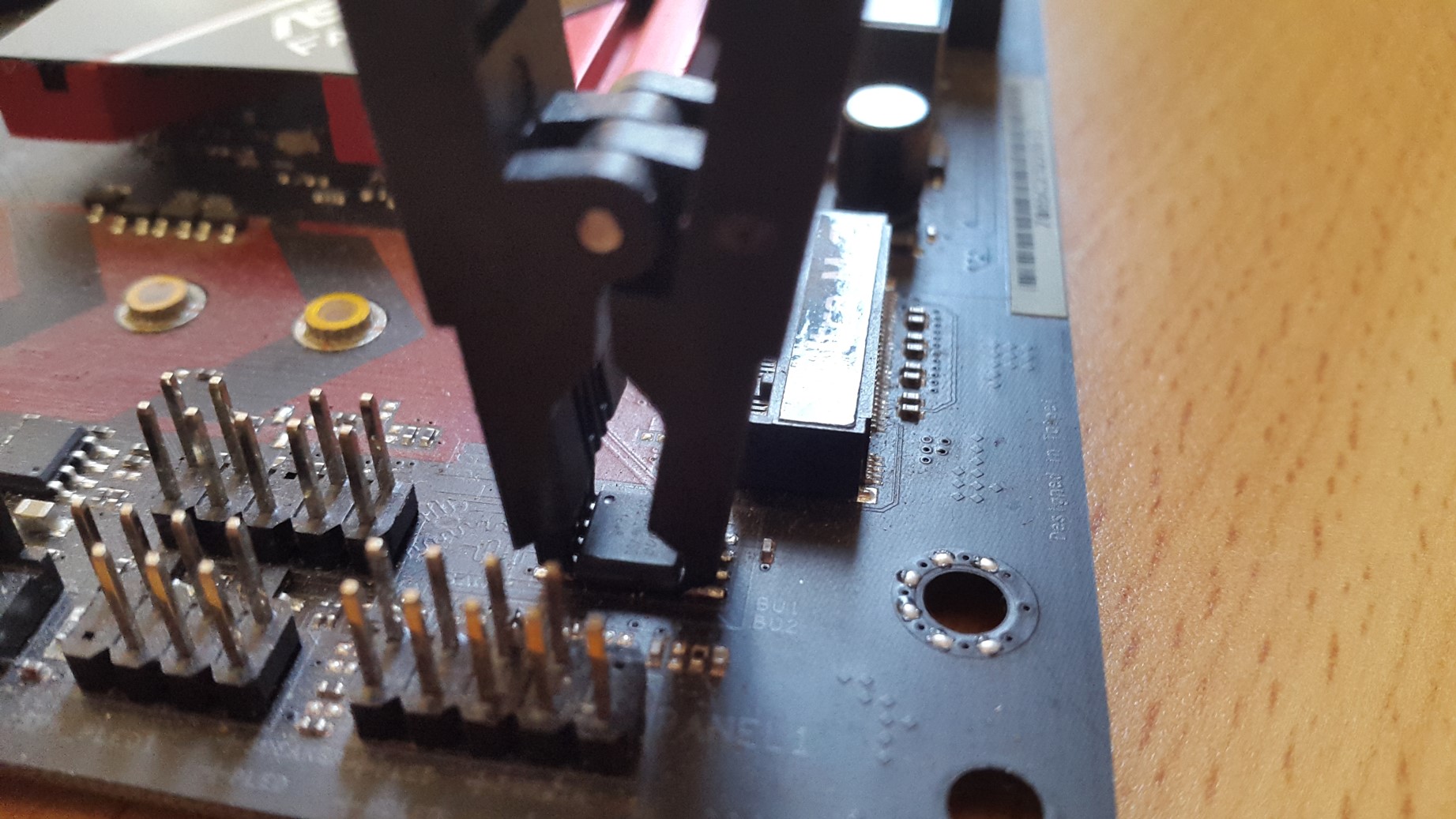
You must now attach the SOIC8 clip to the BIOS chip, like in this picture:
Now, we are ready to flash. Execute the following command in the terminal:
sudo flashrom --programmer ch341a_spi -r backup.bin
This will back up your original BIOS, in the event of a failure. If you are using a SOIC8 clip and get an error, don't worry, this is normal. The clip is very hard to mount correctly, so just take it off and try again, until the command succeeds.
When the backup finishes, we can flash our new BIOS. Run this command, making sure to insert your new BIOS' correct name:
sudo flashrom --programmer ch341a_spi -w <new bios name>
If you have done everything correctly, your new BIOS should be loaded onto your BIOS chip!
If it didn't work, or you need further clarification, feel free to contact me by replying to this thread.
Edit by Fernando: Thread title shortened


