Then your BIOS does not have the 4 modules at the expected locations.
I also have an unsupported Z170 BIOS (it is pre-Kabylake) and was trying to find the relevant 4 modules as they are labelled in a later BIOS (with Kabylake support):
A8499E65-A6F6-48B0-96DB-45C266030D83 = SiInitPreMem 1.0
299D6F8B-2EC9-4E40-9EC6-DDAA7EBF5FD9 = SiInit 1.0
EEEE611D-F78F-4FB9-B868-55907F169280 = PlatformInitPreMem 1.0
59ADD62D-A1C0-44C5-A90F-A1168770468C = PlatformInit 1.0
@Mov_AX_0xDEAD
Here is an example of a BIOS for my motherboard with only Skylake microcode that cannot be patched using Patcher1.3:
GA-Z170-HD3-DDR3 (F6b)
It contains the 4 modules at different locations - can the patcher be easily modified to search for the modules in such a BIOS?
- patcher works only with kaby-bioses, gigabyte marks these versons as F20
- guid numbers don’t matter much, on all kaby-bioses from major vendors they are same
provide link to bios
provide link to bios
Here is an unmodded Bios file.
W650KK1 Bios
tested by me , this version can be patched by patcher 1.3
Do you really mean to replace vBIOS of Z370 Bios (not Z170 one)? If so, how are the steps?
- extract vBIOS of Z170 Bios and upgrade to 1054
- copy modded vBIOS to Z370 Bios
- decomp modded Z370 Bios
- copy bios region.bin to stock (?) Z170 Bios (or to Z170 Bios with vBIOS 1054 ?)
- MC Upgrade
Or maybe I understood totally wrong. Can you give some details on the process?
My goal is to run 8700K on Asrock Z170 and I want to avoid a lot of try and error.
z170’s me config + z370’s bios region + z170’s vbios 1054
no need to modify microcode
@dsanke
All Gigabyte Z370 seem to use 128 Mbit flash and Gigabyte Z170 use 64 Mbit flash for BIOS.
I found a BIOSTAR Z370 Motherboard with 64 Mbit flash (Z370GT6), would a different brand bios.rgn work?
I assume you flash via SPI programmer?
tested by me , this version can be patched by patcher 1.3
confirm, patcher works fine (ver1.4) with this bios
i recommand you change flash chip to 128mb.
All works good on Gigabyte H110M-S2PV-CF
https://valid.x86.fr/vayw5j
Thanks to All!
Asus Z170M-E D3 working good…
Thanks for your sharing.
Complete noob here, but wondering about extra power pins. I’ve seen the tape things that swap pins for LGA 771 to work on 775. They have holes to let all the other pins through, with traces to connect the two pins that were swapped.
Could you make something like that to get the power from the original pins in the socket to the extra pins on the i5-8400? It’s a low power chip, so the current draw should not be an issue for the power coming from the board. The problem would be trying to force the current for six cores through the wrong pins on the chip.
Would you need to have separate traces for every pin, or could all the 12v be wired together, and all the GND wired on one line as well? That would spread the current draw across the socket pins to avoid burnout on that side.
That is not needed. Article with measurements will be out in like 48h tops.
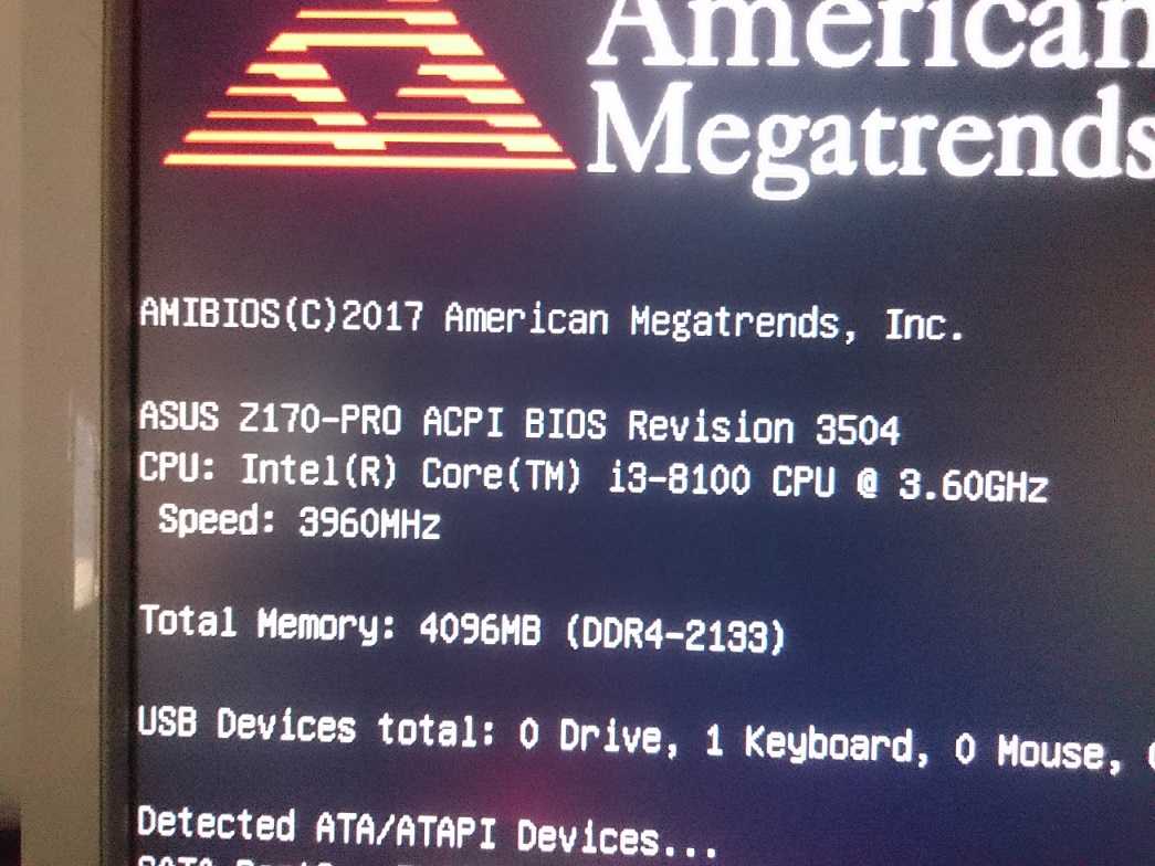
What? I don’t understand, i3-8100 CAN overclock? Screenshot or validation please.
Here screen from Littlehill

BCLK overclock for Non-K Coffee Lake sounds great. On screen bclk=110MHz. Can it be higher? Or this is a top speed?
Does it need special nonK-OC bios?
That is not needed. Article with measurements will be out in like 48h tops.
Where would the article be when it comes out?
Thanks!
Guys, i think the best sweetspot for this mod is also for use with an i5 8400
someone here was tested any motherboard for work with the i5?
I believe here. http://madlittle.com/coffee-lake-mod/
I’ve been trying to wait patiently ![]()