Hi all,
I am trying to read my bios using a raspberry pi and flashrom, but flashrom is unable to identify the chip and will not proceed. The flashrom output is here: https://pastebin.com/a1iQn3bz
I think my chip should be supported, but I don’t see an exact match. The chip has the Gigadevice logo and these id numbers:
BH1632
25LB64CS16
PII039
I think this is probably part of the Gigadevice GD25LQ64 family of chips which flashrom does support, but since the numbers are slightly different I’m not sure. Another possibility is since this is a 1.8v chip and I am using a logic level converter there may be some bad solder joint or some other physical problem. Can it be determined from the flashrom output if it is actually communicating with the chip at all?
Hi!
I found something: "GD25LQ64C and GD25LB64C have the same ID and settings"
And I found even more: GD25LQ64 and GD225LQ64B officially supported since version 0.9.9, 2016-03-13
I can’t seem to find any information about GD25LQ64C support, so I think it isn’t supported yet. You could try to force the chip ID:
flashrom -f -c GD25LQ64(B) <do some stuff>
flashrom man page
PS: I am not responsible for any damage to your hardware, software, yourself and persons/animals near you!
EDIT: first make sure that the chip is wired correctly. It seems you don't get ANY response from the chip (everythig is 0xFF).
Cool. Thanks for the info. If I use the force option for flashrom, am I still in danger of damaging the chip if I only read?
About the 0xff, yes, I saw that and it made me wonder. Is that the default code for "no response from chip" or is there actually a signal getting passed? Since I have never used a logic converter before I am not sure if it is passing/translating the electrical signal properly.
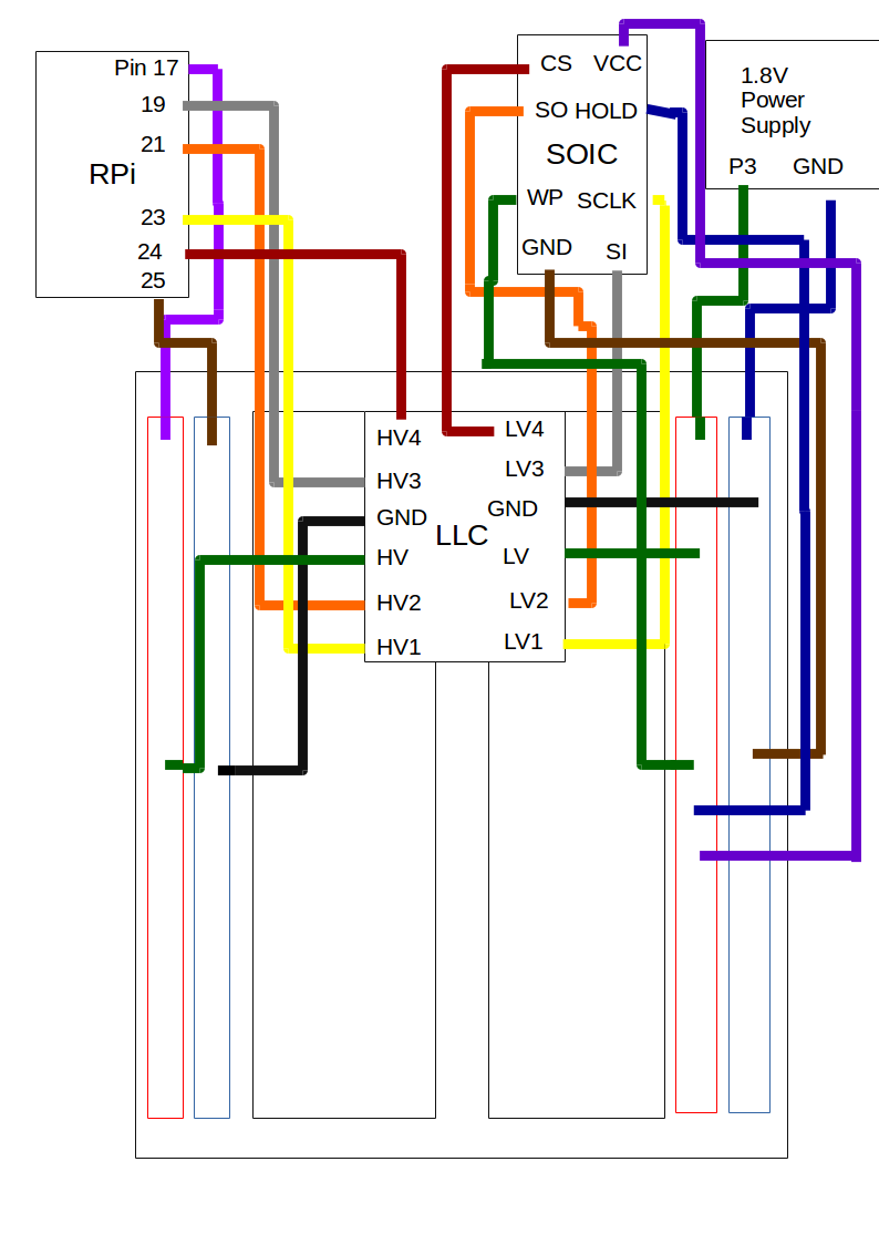
I also was wondering if I wired everything correctly. Have a look. I hope it makes sense. The raspberry pi is connected to the high voltage side and the soic clip is connected to the low voltage side. The logic converter is mounted on a breadboard and the 1.8v power supply is connected to the power rails on the low voltage side.
For anyone else having the same problem, Pacman helped me solve it by putting a 10nf capacitor between power and ground immediately before the chip.