Hi guys,
I am new here.
…and I think now I really messed up big time…
I have a Gigabyte Q87M-D2H. I bought it second hand some two or so years ago. Now I wanted to set up the AMT, and when I pressed ctrl+P I only got a “fw status recovery error”. The CPU is also AMT capable (an i5 4590)
A little background: I do have an Intel DQ67SW and I have used AMT before with that. This other machine is at my parents’ house and until now I haven’t checked the status of AMT.
So when I realized what’s up, and after having googled I came across this thread. I did what I had to according to the descriptions in the OP, and I went through the “D3. ME 7 - 10 & TXE 1 - 2” part, step by step. I even could find the exact same ME fw in the repository, and I know it was a 5MB one.
I dumped the bios and the ME fw was not it that, so I dumped the ME fw separately with the Intel tool.
After that I could complete all steps, I did all the checks, I didn’t get any error messages.
I padded the newly generated file to the size of the original file. I even remember there was a 0x33000 difference.
I did check it afterwards too, all was fine.
I flashed it back with the Intel tool. At the end I got a green text saying the the operation was successful.
After that I did a greset, the pc rebooted, and… died.
No sign of any life. “Please check signal cable” Neither from the nvidia gpu nor from the integrated gpu.
No startup beep.
I tried to reset the cmos but no joy.
What my guess is that I overwrote the bios area with the ME contents but I am not sure. My guess would be that the Intel tool knows what area/part to flash.
So… any ideas how could I fix it?
I do have the bios dump, the original me dump, and an original bios file.
Many many thanks in advance!
You haven’t given any specifics on what tools you used, with what parameters exactly, what files were flashed etc. If the system’s firmware was bricked, you’ll need a hardware programmer to fix it.
Uh, it seems my post from the morning was somehow lost…
Anyhow, here is what I did (some won’t be too accurate as at the very end the pc reset itself, and all the output was gone).
So I wanted to set up remote management, and I realized that the board gave that “fw status recovery error”.
The motherboard is a Gigabyte Q87M-D2H. I bought it second hand some two or so years ago. The CPU is also AMT capable (an i5 4590)
I tried to reset the CMOS, I also tried to reflash the CMOS but none helped. I finally have stumbled upon this thread, and so I followed the steps.
First I have found out that I needed the “D3. ME 7 - 10 & TXE 1 - 2” part as HWinfo told me that the board had 9.1, Build 3002, Hot Fix 42, and also it was a Regular SKU, 5MB firmware. Manufacturing mode active, ME Current operation Mode “Normal” and ME Current Working State “Recovery”.
I could pick this very same ME fw from the repository I had downloaded. I also downloaded the appropriate system tools and all other tools and files as per the instructions.
After this I tried to extract the firmware. I wanted to do a bios dump with fptw64 as I am on a 64 bit Win 10.
I got this:
Intel (R) Firmware Update Utility Version: 11.8.65.3590
Copyright (C) 2007 - 2019, Intel Corporation. All rights reserved.
Error 8753: Restore Point Image Failure.
Error 8828: Restore point operation failed.
I went and checked with memanuf and it immediately reset my pc…
Right after reboot, for the second time, it said something about communication being okay (green text). So I assumed that that part of the fw was okay.
Then I read that I should use the 32 bit version to dump the bios so I can extract the ME firmware. (In this thread from this site - sorry, I am not allowed to post links, so this is the thread: BIOS Modding » BIOS Modding Guides and Problems » [Help] How to dump bios to file)
FPTw.exe -bios -d biosreg.bin
I succeeded but there was no ME fw in the BIOS file. I also downloaded the latest BIOS from Gigabyte and there wasn’t ME fw in that either.
So from here on I went the “ME fw only” way.
I could successfully dump the ME fw by issuing
FPTw.exe -me -d me.bin
(I am writing all this off the top my head but as you will see later all these commands and operations were successful)
I did check the dumped ME fw with ME analyzer and it said the same about it as HWinfo. It said i was an extracted one. I think (but I am not 100% sure) it also DID NOT say it was locked. Date, version all were valid and in agreement with Wininfo.
Then I followed steps 5 with fitc. I browsed and opened the dumped ME fw file.
I made all the changes (I didn’t need to do too much, some were already set to the values in the description).
I am not sure (again; sorry) but as I recall I only had to turn off the Anti theft protection, otherwise the values were as described.
I saved the xml.
I opened the other file, opened the saved config file and built the image. It did complete successfully.
I compared the two xml files wth notepad++. And only the inputfile and the state and the anti-theft technology were different (the reason I remember that the anti-theft settings were okay is that I do remember that the these two were only differing, and no other diffs were reported by np++) I do have the two xml files of course.
I have all the files in fact, of course! ![]() (but on a dfferent pc)
(but on a dfferent pc)
I did not open the two files side by side but I think it was okay after having compared the two xml files.
Since I worked with an engine region only, I did a padding with HxD Hex Editor (the new image was 0x33000 smaller than the original one), so I added 0x33000 0xFF’s to the end.
After that I checked the fw again with ME Analyzer and it also reported that the file has harmless padding at the end. The sizes of the original dumped and the newly generated FW files were the same, I checked them in Windows.
After this I could successfully flash the ME fw… and this is where I am a bit uncertain.
I remember I issued the command:
fptw.exe -f me.bin (since it wasn’t a full bios, it was just the MW firmware)
I got lots of output (programming/erasing/verifying various parts of the flash)
And at the end I got a green text saying that everything was fine.
After that I issued the gsreset command.
The pc immediately restarted (as if the power went away for a second) - and since then… nothing.
I have all the files I used, so if it helps (not to me likely anymore - but to someone later), I can upload them somewhere.
I would be curious what went wrong. I suspect that with the flash command I overwrote the bios area. But: how?
Since then I did yet another thing, that made things even worse…
After the above procedure the cooler spun up. No beep, no nothing but the coolers showed some sign of life.
…so I did a “clear cmos”. I was hoping that maybe it would help. Well, since then the coolers do not spin up at all… ![]() But I guess I have to reflash the bios somehow either way.
But I guess I have to reflash the bios somehow either way.
The motherboard has no dual bios but it does have a blue dot on the (I think second, but definitely not the first) contact of the bios chip. So I hope it is marked because shorting pins and plugging in a usb drive with a bios can revive the motherboard. I have to check somehow.
So… that is the story.
I do have a question though. Since there is no ME FW in the downloadable bios, how can I have a working AMT on that board? let’s assume I can reprogram the bios (I likely will have access to a flash programmer after Easter). But then how can I reflash the ME in a way that the bios survives AND I will have a working AMT…?
Thank you not just for your answers but also for the great and detailed guides and for the enormous effort it took to put together all these infos, collect the files, and making all these available! I really do appreciate it!
Take care!
@bushycell
You say you used FPT but then show a log from FWUpdate and not only that, it’s v11 which has nothing to do with your platform. Even strangely, the FWUpdate command used for that log must have been “-save” which has nothing to do with this problem. Anyway, the command “fptw -f me.bin” using a ME region only caused a brick. You flashed the entire SPI chip with the ME firmware only. FPT must have given a warning saying that the target flash area is larger than the input flash image or similar. The correct command would have been “fptw -me -f me.bin”.
You need to download the latest full (8MB) SPI/BIOS image from Gigabyte and re-flash the 8MB SPI chip using a hardware programmer.
First, thank you for you comments!
Let’s clear up things a little ![]()
As I have mentioned before, I did NOT take any notes. Unfortunately.
So I did a copy-paste of the fwupdate command from a webpage, where the version may be different, but the error message was what I got too.
I did say that I was working with the tools and the version of those from the “D3. ME 7 - 10 & TXE 1 - 2” section. So I downloaded and used those!
Yes, I mentioned fwupdate because at first I had thought I need to use that (based on quick googling), and I got that error message. That made me to look closer, and read more. As a very first step I wanted to dump the bios and/pr the ME fw. And yes, just as you say, it does not have anything to do with the problem. It was just part of what I did.
After these errors I arrived to this forum and your guide.
After that I went through the whole procedure - without any further error.
…except the very last step…
As you mention the very last command… well, I am not sure… but since the command when I could finally dump the ME fw did contain the -me switch I tend to think (! again, I am not sure) that I used that too. I mean it looks very familiar to me.
I am certain that the flash tool did not give me any warnings or error messages.
But on the other hand what eventually happened does contradict this, so I very likely made a typing mistake here…
Right now I am trying to find someone with a hardware programmer. I could buy one but I haven’t needed any in the last 25 or so years, so I think (I hope! ![]() ) that I won’t either for the rest of my life.
) that I won’t either for the rest of my life.
I’ll get back here just for the sake of the archives once I could fix things.
Your help is much appreciated, thank you!
Dear all,
I hopefully get a CH341a tomorrow.
I just have discovered that since I overwrote the BIOS/EFI AND did not dump the original contents with the GBE switch I likely lost the MAC of the GbE controller.
My questions are (maybe to @plutomaniac ?)
- I made a dump with fptw. UEFITOOL does not complain when I open it, so it should be a valid image. On the other hand it is smaller (around 3MB) than the downloadable image (8MB). Is there any hope that the needed info is in it?
- I do have photos of stickers from the motherboard with the MAC and the serial. Could that help? I have found a tool that flashes/changes the MAC for an Intel controller (the eeupdate tool - since I am new, no links are allowed, but you likely now it anyways ![]() ) . Should I use that, or do would you recommend putting it into the image? In this I case I may ask for help!
) . Should I use that, or do would you recommend putting it into the image? In this I case I may ask for help! ![]()
- since I’ll get an SPI programmer I may be able to dump the current state of the chip. Do you think there is a chance that the above info may be found in that dump?
Thank you for your help!
The MAC is found in the GbE Region of the SPI/BIOS chip, specifically at its first 6 bytes. UEFITool can show you the MAC of the GbE Region on the right panel. Once the programmer arrives, you’ll make a full SPI chip dump (8MB) and not BIOS region only (3MB). You can then load that into UEFITool to see if the MAC of the GbE Region has been preserved. If it has, you can take the latest official Gigabyte SPI/BIOS image and replace the 6 bytes at offset 0x1000 - 0x1006 with the ones from your dump. Then flash with the programmer the modified official SPI/BIOS and you should have a healthy/clean firmware with MAC info retained.
Uh, that sounds very good, thank you!
I just have checked the factory bios and it has 500000h padding at the beginning. Is that the place where the ME fw will go? Because this board has a 5MB AMT fw, so 5MB + 3MB equals the bios size. Interesting is that the factory download does not contain the ME fw.
I am asking out of pure curiosity ![]()
This (5MB padding) does also mean that I will have to put (insert, that is, overwrite the 0xFF values with) the MAC values in that empty region?
Oh, and one more question, provided I will not find the MAC in the dump: in what order should I input the MAC values? In the order I read them, from left to right one by one?
I am somewhat familiar with computers but haven’t done anything like that before ![]()
Really thank you for your patience and help!
The stock Gigabyte SPI/BIOS image can be found at their website and file “Q87MD2H.F8” is a full/proper 8MB SPI image with Flash Descriptor, GbE, ME and BIOS Regions. Provided that the current SPI chip dump via the programmer (FD+GbE+ME+BIOS = 8MB) has a populated MAC address at the GbE Region, you can simply “Extract as is…” the GbE Region and “Replace as is…” at the stock SPI/BIOS image from Gigabyte’s website (Q87MD2H.F8) using UEFITool (non-NE). Basically transfer the GbE region from your dump to the clean one and flash the modded stock image back without messing with a hex editor manually (however easy it might be).
Thank you for your answer!
Yes, I did download the stock bios, even before I had began to mess with the ME fw. Mostly, because the description mentions bios, and not only the ME fw. It is described somewhere towards the end that if you work with the ME only then…
And well, it did turn out that that BIOS does not contain the ME image. I have no idea where the ME might hide but it is not in the bios. (see also the attached screenshots)
If you take a look at the bios, as I said, there is a 5MB padding, filled with 0xFF values. Even UEFITOOL lists this.
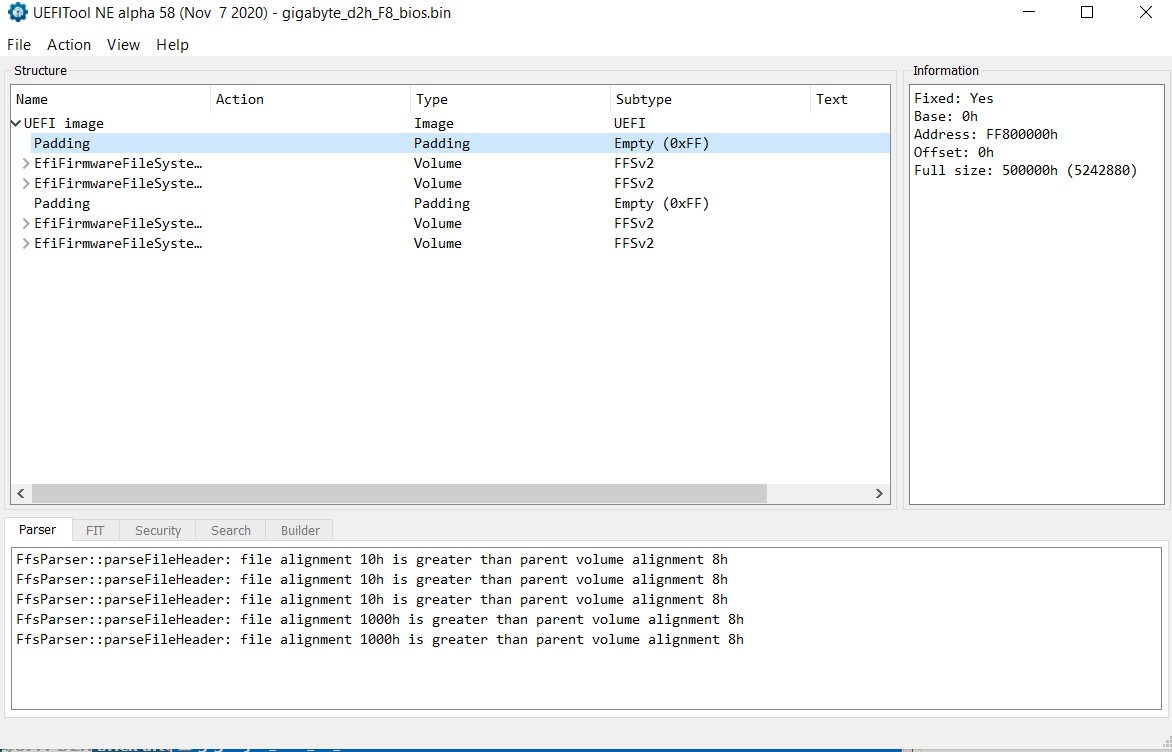
Also, ME Analyzer reports that there is no ME fw in the BIOS file.
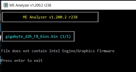
On the other hand I could successfully extract the ME fw and I do have the original one and - as I indicated in my original post - I could successfully generate a "clean" version.
This is basically the source of my confusion.
The term “BIOS” is used broadly/conveniently/wrongly nowadays but as long as everyone knows what it actually is, it is ok. Modern SPI (“BIOS”) chips don’t hold BIOS firmware only anymore. Intel ones follow the Flash Descriptor structure which consists of regions (FD, ME, BIOS, GbE etc) and thus BIOS (or UEFI as it is actually called nowadays) is only one region, not the whole.
Your image consists of the BIOS region only, that’s why it lacks the rest of them (FD, ME, GbE etc). Since whatever image you were using also had equivalent padding (5MB) where the rest of the regions are supposed to be, it is likely that it was dumped from some SPI chip which has read/write protections in place for the non-BIOS regions and thus the end result consists of the BIOS only without the rest actually being there (placeholder data). Usually that’s the work of AMI AFU as Intel FPT shows an access error and does not fill the dump with placeholder padding.
Anyway, just use the official stock Gigabyte “BIOS” (actually full SPI chip image) from their website with the programmer after you sort out the GbE MAC issue first, as explained above.
Many thanks for the clarification. I do know that BIOS is NOT UEFI and that the image may contain other parts.
Meanwhile I downloaded the original “bios” from Gigabyte and there I have all the regions. Strange as I did download it once and that image contains different data. If you look at the screenshots you can see the filename.
Whatever… this is okay now.
Now I can see the “bad” MAC at 01000h in the stock image.
I did get the flasher today but I can’t get it to work. It is very likely a contact issue as the flasher is recognized, and both leds light up. I could only get it to recognize the chip once, but even then it lost contact very shortly after that. I tried it on 3 motherboards. So I first have to sort out this issue.
I’ll get back here for sure!
Thank you very much - again! ![]()