Why do u need the original dump… u have kept ur original data as u said before, so if already have introduced in the flashed bios the original data, u star working with current bios and a new dump.
EDIT: Hey m8…forget the old data and chill out (U have already backed up with FD44 didnt u?), take this as if u bought an used board and u have to repair it. So u do now have a flashed bios and a working system, so make a new dump ans start from here…
wots ur stress about it? Didnt u recover yesterday with the CH341 and with an stock extracted UEFItool Intel image and with the inserted original data (UUID, SN etc…), if im not seeing this correctly plz explain in wot point u r now.
fpt -greset or a total shutdown for a cold boot, board power as to be drain out. If state still persists wait for Plutomaniac opinion, this is field, i only have some general knowledge.
There’s something that’s obscure to me: I esxtracted a configured ME Region from CAP file, checked and it’s Configured; unlocked descriptor and downgraded with extracted ME Region, -greset, system reboots, dump the ME Region, checked and it’s Initialized.
This drives me crazy.
OEM public key hash, how do I clean the me firmware? Intel’s latest 11th generation chipset, the tool I use is flash image tool_ V15, according to your post, I didn’t find the SMIP option! I can’t do the next step, please give me some advice.
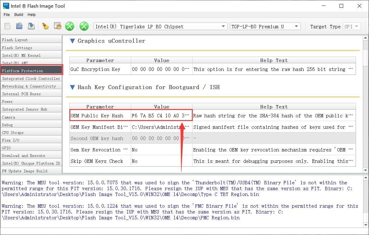
Hi xps 9500 10 gen fit 14
As above no smip in fit also no smip in me analizer how to clen me ???
Please help me point out my problem. How can I solve it without SMIP option!
I’m trying to clean my ME region, and I have a couple of questions, please…
1) the outimage.bin results in Extracted and not Region, is this correct?
2) as the ME region extracted from the CAP file is already Configured, I could flash just that one to have a cleaned region, right?
@ plutomaniac
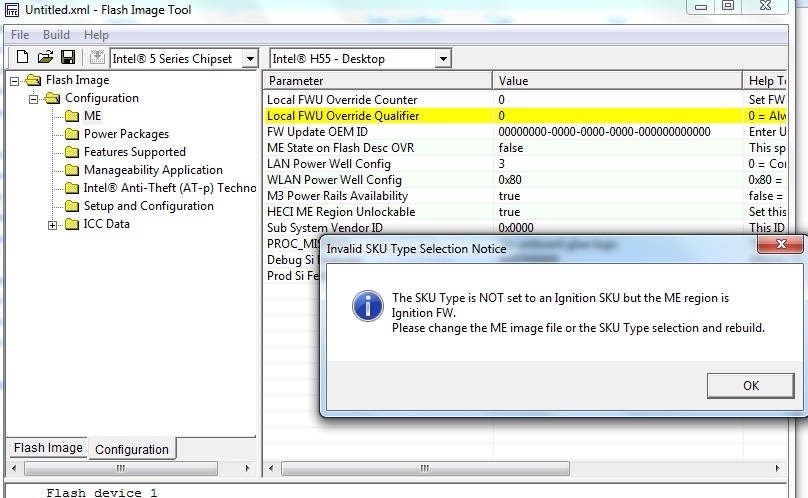
when try to clean me of old version 6 showing wrong sku selection.
even i use same me reposiatory or simply build image without change me its showing same error.
uploading my working backup with reposiatory
please check.
thankyou
backup.rar (792 KB)
Hello sir, I have a question for you. I’ve tried your tutorial. But it was still no display on my laptop. I have tried to replace ME Region so many time. And the result was still same. But when I replace file BIOS Region. It work. So this is my question. What is the different between ME Region and BIOS Region sir?
FIT 12 and 14 refuse to work on a ME region extracted with UEFIToolNE.
Tried extracted ME region from Dell 7080 MFF Enable Intel AMT and out of curiousity extracted ME Regions from a Q370 dump (M920q- ME12) and the stock bios of an Asus Q470 board (link)
Either it’s “Error 237: Failed to load input file. Invalid input file type.” or “Error 9: Failed to decompose Image.” (when removing padding over a certain point).
From the extracted complete bios the ME Sub Partition.bin can be opened in FIT, but it seems to be a constructed file, not part of the original CSE Region. The extracted CSE region.bin is identical to a otherwise extracted ME Region and can’t be opened in FIT.
How can one work on a ME region for ME12 and ME 14? Did I miss something?
That’s normal/expected, as explained here. For CSME >= 12, you need to work on the entire SPI image.
Thanks! But the thread you mentioned was regarding updating ME, not cleaning, and that part is fully understandable.
But regarding ‘getting the configuration’ for cleaning I can’t see the difference in opening a complete ME14- firmware image and a ME14 CSME region compared to ME 11?
OK it might be information added or moved into FD, or- since there were settings stored in FD ealrier, too- they changed the standard behaviour from “assuming default values” to "rejecting the CSME region without information stored in FD"
So for working on a CSME region => ME12 only for cleaning one could use:
- An extracted CSME region and the dumped FD, filling the rest of the firmware with FF, keeping starting addresses or
- An extracted CSME region and any FD fitting for the chipset, filling the rest of the firmware with FF, keeping starting addresses. Settings in FD wouldn’t get touched when flashing back just the cleaned ME so those settings wouldn’t matter or
- An extracted CSME region and any FD fitting containing the right addresses, everything else after 0x7F being FFed (see spoiler), filling the rest of the firmware with FF, keeping starting addresses. Settings in FD wouldn’t get touched when flashing back just the cleaned ME, so those settings wouldn’t matter.
Warning: Could not set "USB3 Port 8 Connector Type Select" to: 0x0000000F, reverting to previous/default value: Type A
Warning: Could not set "USB3 Port 7 Connector Type Select" to: 0x0000000F, reverting to previous/default value: Type A
Warning: Could not set "USB3 Port 6 Connector Type Select" to: 0x0000000F, reverting to previous/default value: Type C
Warning: Could not set "USB3 Port 5 Connector Type Select" to: 0x0000000F, reverting to previous/default value: Type A
Warning: Could not set "USB3 Port 4 Connector Type Select" to: 0x0000000F, reverting to previous/default value: Type A
Warning: Could not set "USB3 Port 3 Connector Type Select" to: 0x0000000F, reverting to previous/default value: Type A
Warning: Could not set "USB3 Port 2 Connector Type Select" to: 0x0000000F, reverting to previous/default value: Type A
Warning: Could not set "USB3 Port 1 Connector Type Select" to: 0x0000000F, reverting to previous/default value: Type A
Warning: Could not set "USB2 Port 6 Connector Type Select" to: 0x0000000F, reverting to previous/default value: Type A
Warning: Could not set "USB2 Port 5 Connector Type Select" to: 0x0000000F, reverting to previous/default value: Type A
Warning: Could not set "USB2 Port 4 Connector Type Select" to: 0x0000000F, reverting to previous/default value: Type A
Warning: Could not set "USB2 Port 3 Connector Type Select" to: 0x0000000F, reverting to previous/default value: Type A
Warning: Could not set "USB2 Port 2 Connector Type Select" to: 0x0000000F, reverting to previous/default value: Type A
Warning: Could not set "USB2 Port 1 Connector Type Select" to: 0x0000000F, reverting to previous/default value: Type A
Warning: Could not set "USB3 Port 10 Connector Type Select" to: 0x0000000F, reverting to previous/default value: Express Card / M.2 S2
Warning: Could not set "USB3 Port 9 Connector Type Select" to: 0x0000000F, reverting to previous/default value: Express Card / M.2 S2
Warning: Could not set "USB2 Port 14 Connector Type Select" to: 0x0000000F, reverting to previous/default value: Express Card / M.2 S2
Warning: Could not set "USB2 Port 13 Connector Type Select" to: 0x0000000F, reverting to previous/default value: Type A
Warning: Could not set "USB2 Port 12 Connector Type Select" to: 0x0000000F, reverting to previous/default value: Type A
Warning: Could not set "USB2 Port 11 Connector Type Select" to: 0x0000000F, reverting to previous/default value: Type A
Warning: Could not set "USB2 Port 10 Connector Type Select" to: 0x0000000F, reverting to previous/default value: Type A
Warning: Could not set "USB2 Port 9 Connector Type Select" to: 0x0000000F, reverting to previous/default value: Type C
Warning: Could not set "USB2 Port 8 Connector Type Select" to: 0x0000000F, reverting to previous/default value: Type A
Warning: Could not set "USB2 Port 7 Connector Type Select" to: 0x0000000F, reverting to previous/default value: Type C
Warning: Could not set "Top Swap Block Size" to: 0x00000007, reverting to previous/default value: 128KB
Warning: Could not set "Intel(R) Precise Touch and Stylus Controller 2 Maximum Frequency" to: 0x00000007, reverting to previous/default value: 24 MHz
Warning: Could not set "TPM Clock Frequency" to: 0x00000007, reverting to previous/default value: 17MHz
Warning: Could not set "Intel(R) Precise Touch and Stylus Controller 1 Maximum Frequency" to: 0x00000007, reverting to previous/default value: 30 MHz
Warning: Could not set "eSPI / EC Slave Device Bus Frequency" to: 0x00000007, reverting to previous/default value: 60MHz
Warning: Could not set "DMI Lane Width" to: 0x00000007, reverting to previous/default value: DMI x4
Warning: Could not set "Intel(R) RST for PCIe-C3 Select x2 or x4" to: 0x00000003, reverting to previous/default value: x4
Warning: Could not set "Intel(R) RST for PCIe-C2 Select x2 or x4" to: 0x00000003, reverting to previous/default value: x4
Warning: Could not set "Intel(R) RST for PCIe-C1 Select x2 or x4" to: 0x00000003, reverting to previous/default value: x4
Warning: Could not set "GbE \ PCIe Port Select 5" to: 0x0000000F, reverting to previous/default value: PCIe
Warning: Could not set "SATA / PCIe Combo Port 5" to: 0x0000000F, reverting to previous/default value: SATA
Warning: Could not set "SATA / PCIe Combo Port 4" to: 0x0000000F, reverting to previous/default value: SATA
Warning: Could not set "SATA / PCIe Combo Port 3" to: 0x0000000F, reverting to previous/default value: SATA
Warning: Could not set "SATA / PCIe Combo Port 2" to: 0x0000000F, reverting to previous/default value: PCIe
Warning: Could not set "SATA / PCIe Combo Port 1" to: 0x0000000F, reverting to previous/default value: PCIe
Warning: Could not set "SATA / PCIe Combo Port 0" to: 0x0000000F, reverting to previous/default value: PCIe
Warning: Could not set "GbE \ PCIe Port Select 9" to: 0x0000000F, reverting to previous/default value: PCIe
Warning: Could not set "SATA / PCIe Combo Port 9" to: 0x0000000F, reverting to previous/default value: PCIe
Warning: Could not set "SATA / PCIe Combo Port 8" to: 0x0000000F, reverting to previous/default value: PCIe
Warning: Could not set "SATA / PCIe Combo Port 7" to: 0x0000000F, reverting to previous/default value: PCIe
Warning: Could not set "SATA / PCIe Combo Port 6" to: 0x0000000F, reverting to previous/default value: GPIO Polarity PCIe
Warning: Could not set "PHY Connection" to: 0x00000007, reverting to previous/default value: PHY on SMLink0
Warning: Could not set "Number of Active Cores" to: 0x0000000F, reverting to previous/default value: All Cores Active
Warning: Could not set "Number of Active Cores" to: 0x0000000F, reverting to previous/default value: All Cores Active
Warning: Could not set "Intel(R) ME Boot Stall Enabled" to: 0x000000FF, reverting to previous/default value: No Boot Stall
[Edit]It seems that in most cases one needs a complete/ valid FD for opening the ME region in Fit for cleaning. Taking an FD from a board with same ME / chipset seems to work after adapting the addresses.
Flash Image Tool (FIT) accepts Engine firmware images in Flash Partition Table ($FPT) format only, which is how the firmware are structured initially and how they were stored in the Engine region of the SPI/BIOS chip up until CSME 11. Starting from CSME 12, the initial $FPT formatted firmware is inputted into FIT, configured and then stored in CSE Layout Table (LT) format in the Engine region of the SPI/BIOS chip, not $FPT. Bottom line is this: you cannot use an (e.g. UEFITool) extracted “Engine” (CSE LT) SPI/BIOS chip region image at FIT for cleaning anymore. You’ll need to have and load the full SPI/BIOS image (FD+CSME+BIOS).
As I could not find anyone confirming they had done it I will report here.
I successfully upgraded my ASRock J4205-ITX that is Apollo Lake Goldmont atom SoC.
ASRock is using full bios update images so there is no need for SPI dump, but just to be safe I used an external programmer to dump the unmodified bios for backup. But it was not needed.
This SoC is still actively supported by Intel in their NUC6 series low power computers. I used MEAnalyzer and saw that although the NUC6 series is running the latest TXE it is not using the latest APL Power Management Controller firmware. Even more interesting is that Intel has quietly moved to newer PMC firmwares over the years on the NUC6 even though they publish quite a detailed bios change log. The most recent 3.1.x TXE that is "clean" is 3.1.75.2351_B_PRD_RGN.bin, so a bit older than NUC6 3.1.86.2538. And just as a precaution 3.1.75 is the last TXE 3 on ARB version 3:
TXE version ARB VCN
3.1.75.2351 3 69
3.1.80.2400 4 71
3.1.86.2538 5 82
Some documentation suggests that once ARB version number is updated in the chip it is impossible to revert to previous version even if you have a valid SPI image dump.
So that is why I chose APL_0.1.0.0_B_2019-02-04_PRD.bin for the PMC to match latest NUC6 bios and 3.1.75.2351_B_PRD_RGN.bin for TXE. And of course the latest microcode can be used when creating this new bios image. Although for a simple microcode update operation the complex FIT process is not needed, one can use a hex editor replacing the included microcode with a new one and no other checksum etc fixing is needed for this bios image. ASRock uses no verification on this bios so flashing the modified image from the bios setup was straightforward.
In the end the versions updated:
TXE 3.1.50.2222 > 3.1.75.2351
PMC 2016-08-10 > 2019-02-04
MC 2E > 46
True, but it started to apply from CSME 12 and newer firmware. It was optional at first but became obligatory afterwards (CSME 13 maybe, don’t remember). For CSME 11 and CSTXE 3-4, neither TCB nor ARB SVN are enforced through the HW/Chipset/Fuses so you can go back to older values with external means (programmer etc).
CSTXE 3-4 used IFWI 2.0 which includes the microcodes within a $CPD partition, just like CSTXE code & data. The $CPD header does have a Checksum-8, but it covers the offset & sizes only, not the data (microcode) afterwards. However, if the new microcode is smaller or larger, the equivalent $CPD Entry fields will need to be adjusted, which will require calculating the Checksum-8 again. I assume it worked in your case because the new microcode was of the exact same size, but it’s not always like that. You can check these things via MEA unpacking (-unp86 -bug86) for CSTXE.
Could someone help me clean my ME region DATA to return to full corporate AMT from Small Business Tech? My Lenovo X1 Yoga 2nd generation (skylake i7 7600u) went from full corporate to Small Business Technology CSME 11.8 after switching wlan adapters.Here is the ME region dump. Sorry for posting in multiple threads. Is it enough to reset the FW Capabilities value perhaps?
MEInfoWinVerbose.txt (8.7 KB)
I want folow your instructions but have some diferences:
After put Bios dump in v7.1.13.1088 FITC the size of Me region.bin in Decomp folder is 812Kb and in ME 7 Repository r30 file size is 7.1.13.1088_1.5MB_PRD_RGN.bin
Do i should just rename right file reposytory nad paste it?
Also dont have these options:
"Boot Guard Profile 0 - No_FVME". Also, go to "Flash Image > ME Region > Configuration > Integrated Clock Controller" and make sure that "Default Lock Enables Mask" is not set to "Unknown". If it is set to "Unknown", change it to the default value of "0:Default".
Is it better to update the bios before the dump clean or afterwards, does it matter ?
Before using same version on current bios, as the update bios can have also an upgrade for the ME.
Usually a bios upgrade on top of a corrupted ME FW image doesnt solve anything so better to do it in current bios version and later upgrade.
alright thanks @MeatWar
gonna do it tomorrow and report back
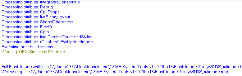
I was able to dump the bios chip and cleaned it following the tutorial.
Before I flash it I would like to double check, fit returned 2 warnings during build.
Especially the PPT will be disabled permanently in HW is worrying (hardware fuse?). Currently it does support TPM 2.0 via CPU
Is it safe to flash this ?
I also attached the me analyzer output for both.
Thanks in advance and a nice weekend.
edit: double checked everything and flased the cleaned version
everything works like a charm (the pc rebooted 3 times first, took about 90 seconds to boot up)
me analyzer cleaned.txt.txt (10.1 KB)
me analyzer.txt.txt (10.1 KB)