Finally got the CH341A recognized. Seems like Windows 11 likes 2.5 PAR driver. Anyhow was using the wrong size soc connector I think. At least its recognized except Windows will disconnect the device if it has a bad a connection. Hope I didn’t fry my CH341A device. Wish it was boxed in plastic or in a case to protect it. Will have to look for the right size connector and try again. Thanks.
Is it the common design with a black PCB? Is the red LED on when you plug it in?
Does it appear in Device Manager? I used some version of NeoProgrammer and installed the driver that came with it. It worked like a charm.
Where are you getting this information from? I can check the version numbers for you if you want? But I’m on Windows 10. As I have only used NeoProgrammer, and I had good experience with the setup, I can only recommend that.
Depending on batch or version, these SOC adapters are sometimes labeled, and sometimes not. Mine are not labeled, except for one I think. So it depends on what you get in the package. Check before you connect. Do you plan to use it out-of-circuit? With chip off the board?
I know what you mean. I used mine for in-circuit programming, and I had the programmer lay on top of the PCB of the tablet that I wanted to read the chip from. What I did is I put a small plastic zip bag between the tablet PCB and programmer PCB for isolation. I would suggest you do the same.
Also, the programmer weighs almost nothing. So I had the USB cable looped through the loop of my hot air station (it was off) and to the side of my keyboard to avoid pulling or sliding the USB cable and the programmer moving around.
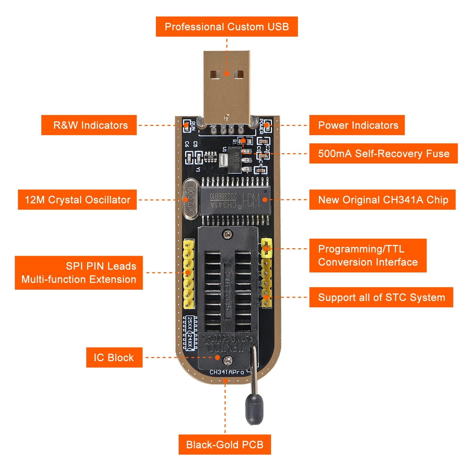
Yes. It is the common design with black pcb and the LED is red when I plug it in to the usb port. Light goes out when the test clip is in use. Also the bridge board that plugs in to the grid is blue.
Since PAR ver 2.5 it does appear in device manager now but fades out in device manager when connected to a test chip. Think was because was using wrong size test clip.
I wasn’t using Neo Programmer but just found a copy on my hard drive coincidentally so will try it out.
Was planning to use it with chip connected to board on an HP Prodesk SFF 600 (talking about it on other thread). Tried to connect yesterday but failed. Thank god it still works. For testing I have an old spare Winbond chip but that chip is bigger than the one on the HP.
I also am curious weather or not I can reflash an old Pioneer Bluray drive. to a previous version using the programmer. Think that one has a 16 pin bios chip. Will have to take it apart and see.
I also own a flash Cat Usb programmer but that one requires pin to pin direct connection which I once did but I am sure there is an adapter somewhere I am not aware of that allows direct soc clip connections. Anyhow when not lazy I use an old antistatic bag but lately just winging it…
Thanks
Never out on mine… the power indicator stays on (RED)
and the operations R/W led when in use (AMBAR),
also when there’s a bad connection/wrong pins assignment, the 2 leds will go both RED.
Colors will differ from vendors, can be both red or red/green/ambar.
One thing to consider here is to only connect the programmer to USB/power after making the appropriate connection to the chip (disconnect in reverse order). Especially if you’re trying to connect a SOIC8 test clip directly to a chip on board for in-circuit programming. You want to make sure you make a good connection and correct connection, before you put the power on.
Also, I didn’t find any explicitly stated instruction in this guide and in other guides on this site saying that you need to have the laptop/tablet powered off. But it is implied, and common sense dictates that it should be powered off.
However, on other sites, some people are saying that the current delivery from the CH341A programmer may not be enough to power both the BIOS chip and the rest of the board, and that you should have the board externally powered.
I would not recommend it! I would power the board off before connecting the programmer for in-circuit programming. That’s what I did, but although with a low-powered Windows 10 tablet, and it worked immediately. Also, take the CMOS battery out (CR2032) if there is one (there was none in my tablet), before you connect the programmer.
So my recommendation:
- Power the board off.
- Take the CMOS battery out.
- Disconnect main battery if it’s a laptop/tablet (or disconnect power cord if it’s a desktop).
- Connect the SOIC8 test clip to chip.
- Connect the programmer to USB port on the computer.
I don’t know if this is the reason you’re having issues. But this is what I did, and the reasoning I used. This was in fact the very first time I ever did something like this, and it worked like a charm. I think CH341A is a very good choice for a hobbyist and DIY repair guy like myself.
By “grid”, you mean the black ZIF socket on the programmer? And by “bridge” I assume you mean the different adapters. They are usually blueish in color, more like cyan. I used one of those adapters for 1.8V because that’s what my chip was using. You have to make sure you get the pins correctly. There are two compartments in the ZIF socket on the programmer, one for SPI and one for I2C (you can see from the bottom of the programmer).
Is this a loose test chip or is it soldered on to a test board? Do you have another USB cable you can try? Is the cable very long? Do you have anything else connected to that USB port like a USB hub? The cable could be bad, or if it’s very long and you have other devices connected via USB hub, you could be having a voltage drop (however small). Make sure you have nothing else connected to that USB port to ensure you get maximum power out of it.
I checked the version number for you. I used NeoProgrammer 2.2.0.8.
I got it from a site called Khan Dish Network:
https://khandishnetwork.com/download/neoprogrammer-software-2021-v2-2-0-8-22-06-2021/
I don’t have it connected right now, so I can’t check it in Device Manager, but here’s the driver version info. It’s version 2.2.2009.06.
[Version]
Signature = "$Chicago$"
Class     = WCH
ClassGuid = {77989ADF-06DB-4025-92E8-40D902C03B0A}
Provider  = %WinChipHead%
DriverVer = 06/05/2009, 2.2.2009.06
CatalogFile.NT = CH341WDM.CAT
I don’t know what SER and PAR drivers are, but this is what I used. I hope it helps.
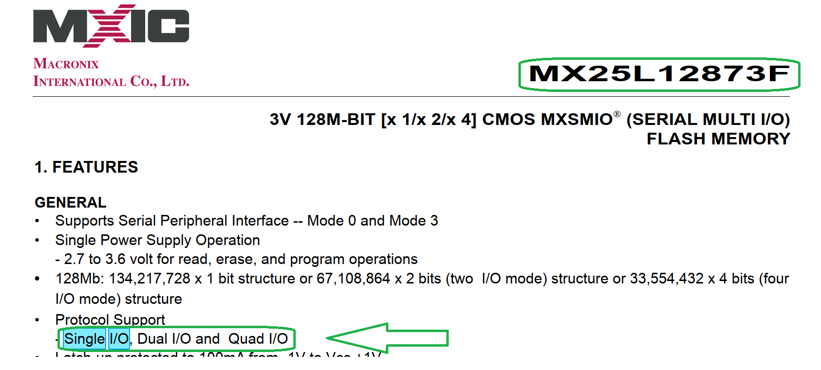
So last night tried to make a connection to the MX25L12873F Matronix flash chip with a test clip and tried AS Programmer, Neo Programmer, and CH341A Programmer software and all three failed to get a proper read off of the MX25L12873F. I did not attempt to flash it until I figure out the issue. Read the technical document and according to the PDF it is a 3.3v chip. I google searched the MX25L12873F and there are multiple threads about bad reads and people not having luck flashing it. Some suggested it might be write or read protected. Even with the chip desoldered they had the same problem. Right now my best guess in my case is a poor connection maybe I need to use a test clip one size bigger. Wil try that theory out tonight but as others have also had same issue not sure that is the problem. I also will try my FlashcatUsb programmer and see if that works but before I do wonder if anyone out there has successfully flashed the MX25L12873F and how you did it? Thanks
According to Chatgpt the MX25L12873F is not compatible with the Ch341A!
Chatgpt:
Your CH341A programmer is likely failing because it does not support Quad I/O mode, which is always enabled on the MX25L12873F. Try one of the workarounds or a different programmer that supports Quad SPI.
Macronix Serial Multi I/O (MXSMIO™) Flash provides not only Single I/O, but also Multi-I/O interfaces. MX66xxx35 or MX25xxx33/35/39/73/75 series offering Dual I/O or Quad I/O operations which double or quadruple the read performance of systems for high-end consumer applications.
Datasheet
I’d rely on datasheets instead of blindly trusting unreliable sources and spreading wrong information.
There are in addition several reports of this chip type being read and written without problems. That excludes normally a systematic problem with the chip type and reduces the possible causes to board design or operator error.
I’ve been “picking” with some users that come here to this forums with such “results”…
and there is your answer from lfb6…
We cant and shouldn’t rely on these “Primitive” technologies and “fill” their owners greed…
and we are talking of delicated programming operations, man maid and manned…
Let those things tell you some hotels, shops or partys near you… that’s its.
I keep askting them how to get rich before i died… the only anwser is, first make them “rich”…
Cant you guys understand that all this “thing” does is to collect published offical and non official, tons of BS etc… around the web and interpreted as the 'Thing" wants, giving you
Call me whatever you guys want…i dont mind, but please keep this forum alive with real persons with all the mistakes humans do.
Thank you.
1 Like
There is no need to “pick” on anyone. I find that in poor taste and not appreciated. Apologize if I misinterpreted the intent.
I did look up the specs and did a lot of research with Google reading other peoples experiences with this chip. A lot of people had issues trying to flash the MX25L12873F. Some thought there was a write once or some sort of security on the chip that prevents writing with certain devices. One guy actually desoldered his MX25L12873F to rule out poor connection and had the same result. I personally would love to hear from those who were successful what software version of what software they used.
In any case I looked up the technical document on this chip and it confused me:
The MX25L12872F product provides a feature rich solution to cover legacy products including
MX25L12835F/33F/73F.
The Configuration Register sets the number of dummy clock cycles used for fast read operations, the
output drive strength, and selects either the top or bottom of memory to be a Block Protect (BP) area.
The MX25L12835F/33F/73F and MX25L12872F devices support an individual block protection
method as an alternative to the grouped block protection provided by Status Register Block Protection
(BP) bits. In addition, all of them have added additional protection features in the Advanced Sector
Protection mode that provide higher levels of protection. These higher levels of protection include:
- Nonvolatile individual sector/block protection.
- A software locking mechanism to prevent modifications to the nonvolatile protection until the
next reset cycle or power-up cycle. - A password protection cycle (only provided by MX25L12835F/73F).
These additional protection features can be used to prevent accidental or deliberate data corruption
in protected memory areas.
For the comparisons of MX25L12835F/33F/73F and MX25L12872F, the differences are listed as
below: - Secured OTP: Both MX25L12833F and MX25L12872F have additional 8K-bit secured OTP
mode, while MX25L12835F/73F have 4K-bit secured OTP mode. - Fast Boot Mode: The fast boot mode is only provided by MX25L12835F/73F.
- Password Protection: The password protection is only provided by MX25L12835F/73F.
- The Quad I/O mode is permanently enabled on MX25L12873F and MX25L12872F.
Please refer to the MX25L12835F/33F/73F and MX25L12872F datasheets for more details.
Thank you
Im not and i don’t judge poor decisions, besides not being the best ones.
Thank you.
So no one can comment on how to program a quad spi chip?
Well I have tried two different test clips and two different usb programmers and get nothing. Chip not detected accross three different applications. Maybe can’t make good contact or chip is dead.
Thanks
original pic
This is the chip?

Are the some of the pins 2,3,4 connected to the same (marked) rail or is this just because of a unsharp pic?
Yes. Thats the chip. MX25L12873F and it has 8 connections but not sure about its rail topology. Maybe board needs to be powered on?
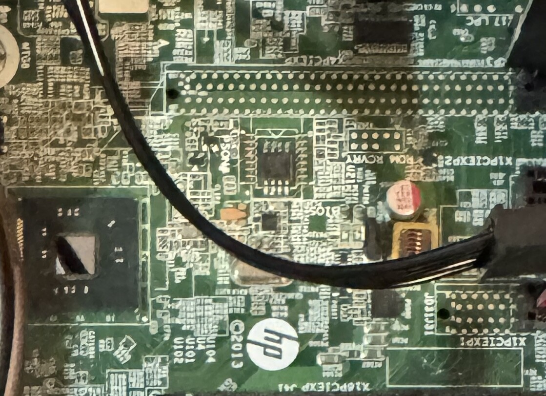
Interesting move to replace a pic with another pic that shows even less.
Good luck!
Interesting move to replace a pic with another pic that shows even less.
Good luck!
[/quote]
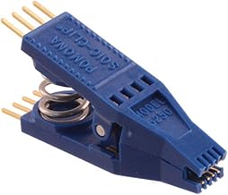
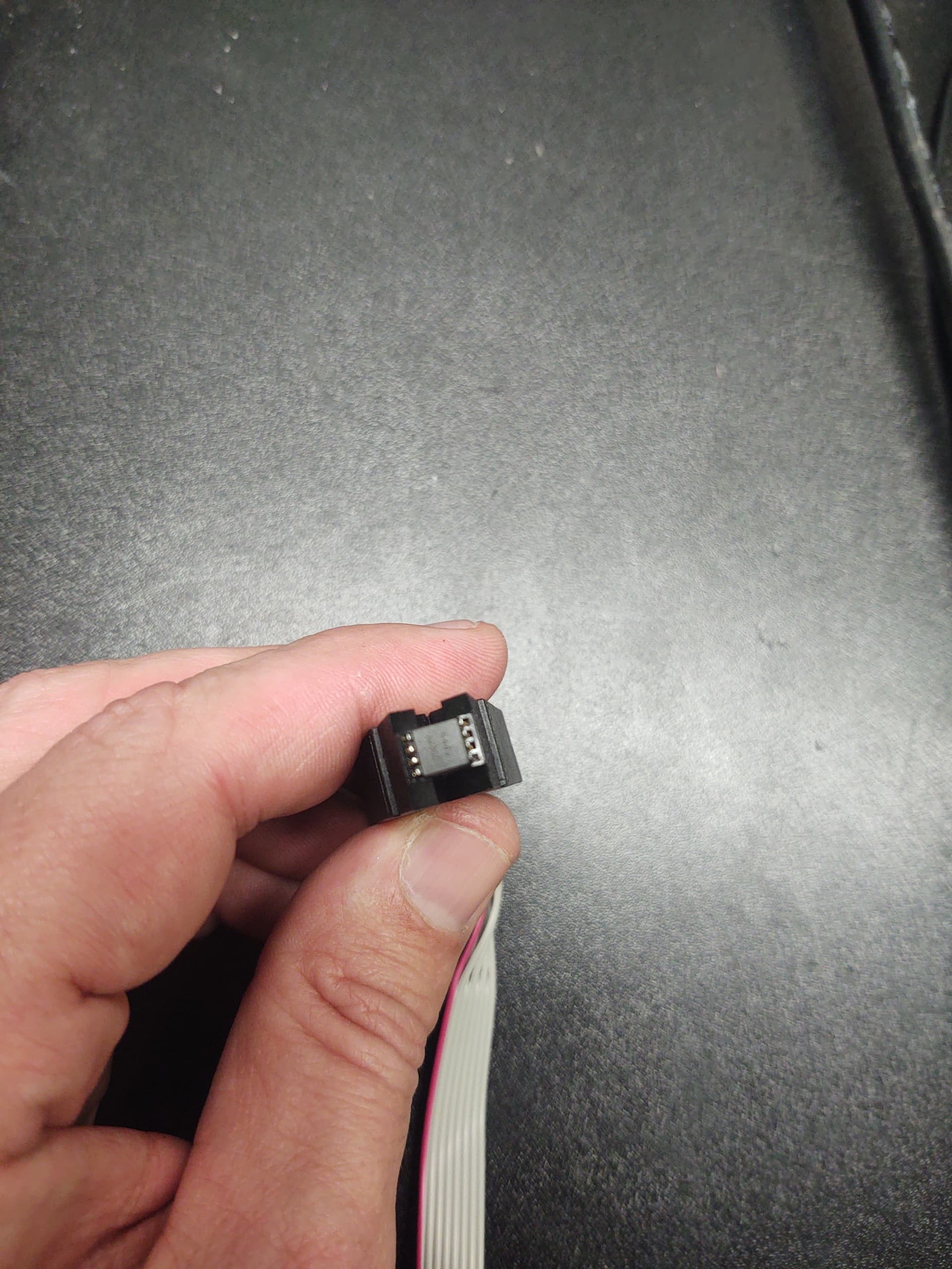
Sorry was on way to work. Will take better picture of what clip looks like seated. For now let me show this is what I am using:
 [quote=“lfb6, post:69, topic:32948, full:true”]
Ive had to remove the BIOS chips more common than not for it to allow unlocking and reprogram. its not the easiest task, but it worked almost every time i had the same situation you have. Other than that , make sure you have the correct CH341A driver installed for the device. ive came across that issue as well.
image for example
Thanks Nate for the advice. Was finally able to make a connection to another test board which was a dead x79 board I had forgotten about. Started off just like before. Couldn’t read the chip. After like 50 tries I held down the clip directly centered as if I let go it would move or shift. Finally As Programmer read the chip and took a bios dump which I was able to open in uefitool. Will try it again on my intended target board tomorrow as this was exhausting. Though the x79 board had a LED light that would go on when I made the right connection to the chip which helped guide me in the right direction knowing that I was mounting the clip correctly. Unfortunately or not the HP prodesk not light up and it will be harder. I’m sure desoldering the chip be easier in that regard and safer considering may not want voltage spilling over the rest of the board. Anyhow will try again tomorrow.
Thanks