There is no need to “pick” on anyone. I find that in poor taste and not appreciated. Apologize if I misinterpreted the intent.
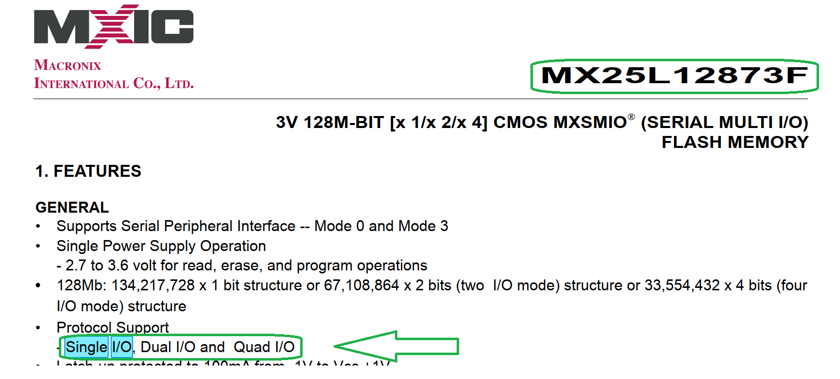
I did look up the specs and did a lot of research with Google reading other peoples experiences with this chip. A lot of people had issues trying to flash the MX25L12873F. Some thought there was a write once or some sort of security on the chip that prevents writing with certain devices. One guy actually desoldered his MX25L12873F to rule out poor connection and had the same result. I personally would love to hear from those who were successful what software version of what software they used.
In any case I looked up the technical document on this chip and it confused me:
The MX25L12872F product provides a feature rich solution to cover legacy products including
MX25L12835F/33F/73F.
The Configuration Register sets the number of dummy clock cycles used for fast read operations, the
output drive strength, and selects either the top or bottom of memory to be a Block Protect (BP) area.
The MX25L12835F/33F/73F and MX25L12872F devices support an individual block protection
method as an alternative to the grouped block protection provided by Status Register Block Protection
(BP) bits. In addition, all of them have added additional protection features in the Advanced Sector
Protection mode that provide higher levels of protection. These higher levels of protection include:
Nonvolatile individual sector/block protection.
A software locking mechanism to prevent modifications to the nonvolatile protection until the
next reset cycle or power-up cycle.
A password protection cycle (only provided by MX25L12835F/73F).
These additional protection features can be used to prevent accidental or deliberate data corruption
in protected memory areas.
For the comparisons of MX25L12835F/33F/73F and MX25L12872F, the differences are listed as
below:
Secured OTP: Both MX25L12833F and MX25L12872F have additional 8K-bit secured OTP
mode, while MX25L12835F/73F have 4K-bit secured OTP mode.
Fast Boot Mode: The fast boot mode is only provided by MX25L12835F/73F.
Password Protection: The password protection is only provided by MX25L12835F/73F.
The Quad I/O mode is permanently enabled on MX25L12873F and MX25L12872F.
Please refer to the MX25L12835F/33F/73F and MX25L12872F datasheets for more details.
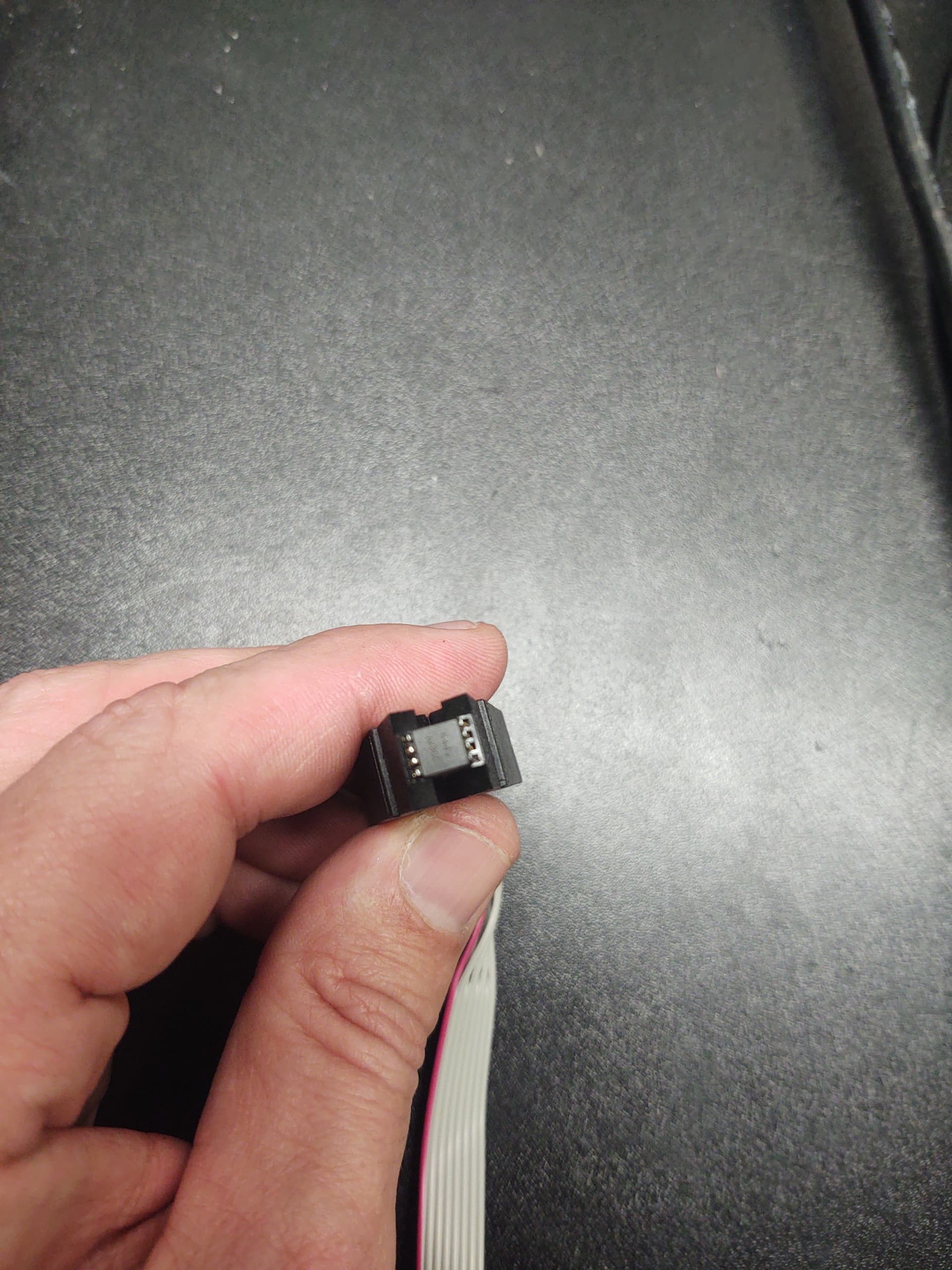
Well I have tried two different test clips and two different usb programmers and get nothing. Chip not detected accross three different applications. Maybe can’t make good contact or chip is dead.
Interesting move to replace a pic with another pic that shows even less.
Good luck!
[/quote]
Sorry was on way to work. Will take better picture of what clip looks like seated. For now let me show this is what I am using: [quote=“lfb6, post:69, topic:32948, full:true”]
Ive had to remove the BIOS chips more common than not for it to allow unlocking and reprogram. its not the easiest task, but it worked almost every time i had the same situation you have. Other than that , make sure you have the correct CH341A driver installed for the device. ive came across that issue as well.
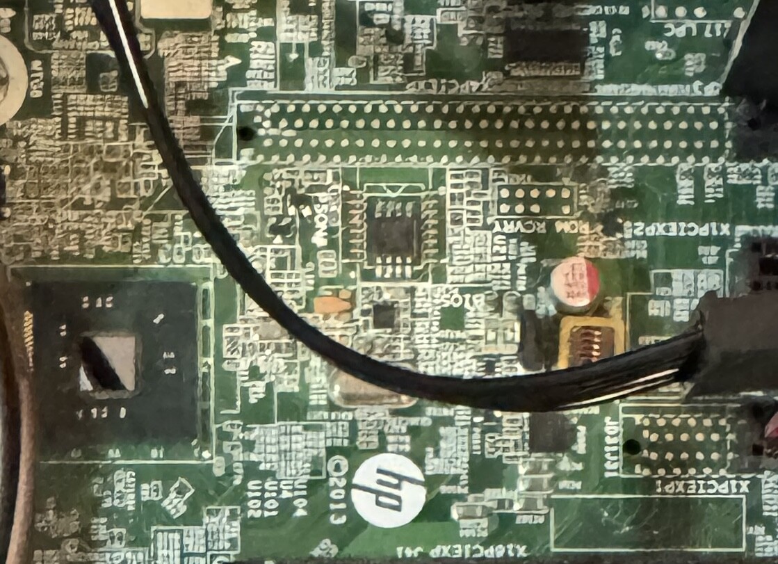
Thanks Nate for the advice. Was finally able to make a connection to another test board which was a dead x79 board I had forgotten about. Started off just like before. Couldn’t read the chip. After like 50 tries I held down the clip directly centered as if I let go it would move or shift. Finally As Programmer read the chip and took a bios dump which I was able to open in uefitool. Will try it again on my intended target board tomorrow as this was exhausting. Though the x79 board had a LED light that would go on when I made the right connection to the chip which helped guide me in the right direction knowing that I was mounting the clip correctly. Unfortunately or not the HP prodesk not light up and it will be harder. I’m sure desoldering the chip be easier in that regard and safer considering may not want voltage spilling over the rest of the board. Anyhow will try again tomorrow.
I’m trying to flash the bios of an old Compaq CQ57 laptop with a bios chip PCT25VF016B (3.3V).
The orange light on the programmer stays on for 7 seconds, flashes and then turns off after 3 seconds. By the time I try to read the BIOS I’m getting a message saying the IC is not responding / disconnected in the NeoProgrammer.
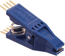
There’s a slight bent when I lock in the SOIC8 adapter with the lever.
Some SPI ICs must be de-soldered and programmed outside the PCB, a few percentage mbs require PSU stand-by power or main battery.
The adapter can be lifted 1mm and should not be “bent”
Never let the programmer PCB touch another pcb circuit board…
And this is never an easy operation for beginners that have never done it before and still haven’t acquired experience with these “cheap” programmers.
Hi,
I have two BIOS chips for a Dell Inspiron 15R 5520:
a cFeon QH16-104 and a Q32B-104.
I desoldered both of them and tried to program them using a black programmer.
The smaller chip (cFeon QH16-104) shows some data, while the other one (Q32B-104) shows nothing but FF.
I tried to remove the protection and write new data, but every time during verification I get the message:
“Buffer data does not match SPI chip.”
I hope someone can help me out.
software been used ( NeoProgrammer / CH341A Programmer / AsProgrammer )
EDIT: Try Colibri or older ASprog
So it can read/write correctly on the EN25QH16…you know this for sure…cause you verified the data…, but not on the EN25QH32?
So, will it remove the protection? I’m not sure if it will damage the BIOS or not
I’m thinking of trying it on this chip (W25Q32B) because it’s acting the same way(Buffer data does not match SPI chip).
I might be in the wrong section i wasn’t sure where to post. I bought one of those ch341a usb sticks off ali express i downloaded the software off the internet to read an eeprom chip on my cars ecu. for an unknown reason it doesnt work or im doing something wrong. does anyone have any tips? some say on the internet that the voltage is wrong or there was some faulty ch341a going around or something and it needs to be 3volts not 5v

 [quote=“lfb6, post:69, topic:32948, full:true”]