[Guide] How to flash a modded AMI UEFI BIOS

@Fernando so I’m just update with EZ Flash Utility from the BIOS to previous 4804 bios version is succesfully installed. I can now know if mod bios works or not. so I’m going to flashback method with your R4G.CAP wish me luck!
I will update news soon.

@memomix @Paulos7 @Lost_N_BIOS @Durahl

Since our recent discussion has not much to do with the topic “How to get full NVMe Support”, but matches exact the title of this thread, I have moved all your recent posts regarding memomix’s problem here.
Hoping, that this is ok for you.

@memomix :
Good luck (finger crossed)!

@Fernando Unfortunately Asus Flashback Method isn’t working,now I’m sure with 100% so the all matter is find a way update to Mod Bios with another method. What do you suggest?

@memomix :
Contrary to you I am confident, that the ASUS Flashback method will work even for you, if you find an appropriate USB Flash Drive.

FINALLY WORKED!

Dear @Fernando and @Paulos7 and @Lost_N_BIOS I appreciate you many for trying to helping me in this situation.Very Big Thank you all!

So how did I do that?
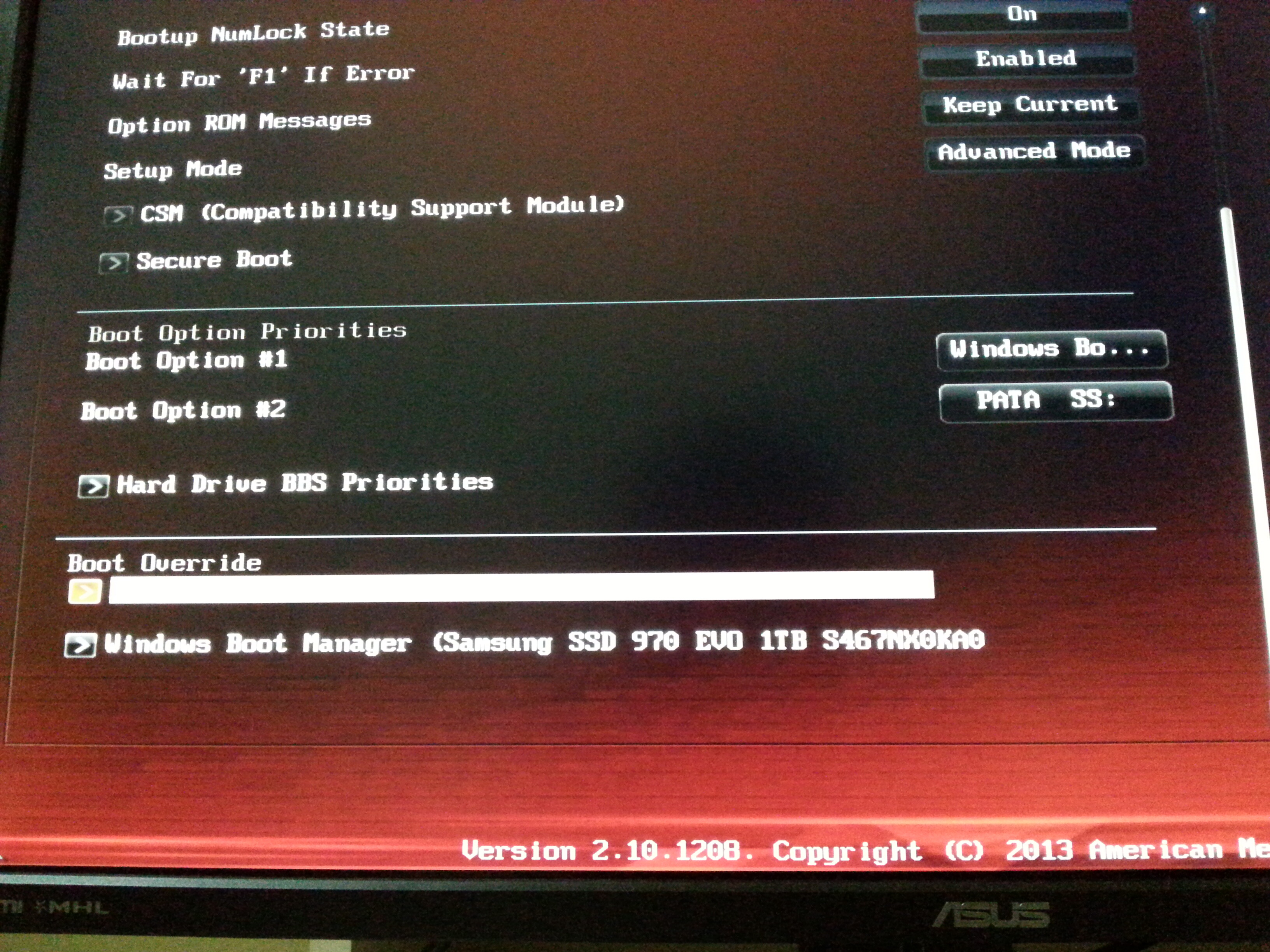
First,I tried THIS METHOD and finally I updated Fernando’s “R4G.CAP” so after I entered in Bios and I changed CMS Options with UEFI and I disabled Secure Boot,Fast Boot Disabled and saved with F10 and shutdown my pc first. then I plugged my HDD again and Showed up my “970 EVO SSD” with PATA and PATA SS in the “Boot Priorites” I attached the pic. I’m very happy,I think It was worth it at the end of 4 days. I couldn’t have done it without you guys… especially Fernando! you’re the best! Thanks again.

20181203_042430.jpg

@memomix ,
I didn’t watch the whole video, but I guess it showed you a different way to flash the BIOS with AFUDOS, correct? I noticed that it said CSM had to be enabled for AFUDOS to work. I don’t have any experience with EZ Flash, but I wonder if CSM needs to be enabled for EZ Flash to work also? Anyway, I’m glad to hear that you finally got it to work.

@Paulos7 yes with AFUDOS I created a bios boot usb. I tried with CSM Enabled to EZ Flash but EZ is only accepting official bios not with modded.Anyway thank you again.

@Fernando you said that so how can I update this cpu microcodes in bios?

The easiest way is to let the UBU tool do the work (look >here<), but this is not the topic of this thread.
By the way -here you can see the pictures I took before (left Pic) and after (right Pic) having updated the CPU microcodes of your mainboard BIOS by using the UBU tool:

@Fernando is this mandatory for the update microcodes to do in the bios? it seems everything working fine after updated with your modded bios,I don’t wanna rollback again mess up with this situation, I already installed Windows 10 and using without any issues… What will happen if I don’t update it?

Probably nothing, but your PC is vulnerable due to the “Spectre” and “Meltdown” problems of Intel CPUs.

@Fernando ok I will try to update and let you know the result in other thread. Thank you.

This method can be added to first post for Asus @Fernando - works in some instances where other methods do not and user is not interested in getting too involved (grub/FPT) - direct users to “Third Spoiler Only” for flashing info
https://linustechtips.com/main/topic/592…r-motherboards/

@Lost_N_BIOS

Done! Please le me know, if anything should be wrong or misleading.
Thank you very much for your advice and the link to the tricky procedure about how to circumvent the ASUS BIOS protection.

Thank you @Fernando looks good! Any and all methods we can add will help members, because as you know all situations and user experience/knowledge on how to use tools differ, and sometimes user can try several methods and none work.
The more possible methods we can provide to help users the better the outcome will be in all situations.

Hey guys - thanks for helping me out so far! I now have both the CH341A programmer and the SOIC8 clip (although I did not get the cable/board which connects it to the programmer so I had to manually connect them with wires). I have a few questions:
- My motherboard (S1200V3RPS) has two 8 pin chips which I assume each contain firmware (they are the only two chips on the board covered with stickers). I believe one of these is the BIOS and the other is the BMC firmware (the Baseboard Management Controller on Intel boards). Is there any way to verify this? (I will try removing the stickers tomorrow to see if there are part numbers on the chips.)
- Does the SOIC8 connector go to the BIOS (SPI) or EEPROM (I2C) portion of the programmer?
- I have the black version of the CH341A and I read on this forum that this version has an issue where it outputs 5V to the chip instead of 3.3, is there a way to verify that the chip supports this?
- Would this be the correct way to wire the pins to the programmer, and which side of the programmer does pin 1 connect to (I believe it is the side closest to the lever)? https://wiki.gentoo.org/images/c/c7/Flash_8_pinout.png
- When flashing the chip in-circuit, should I have the board powered off but plugged into the wall (so the standby power is on) or completely disconnected from power?
I apologize for the large amount of questions - I just want to make sure I flash the BIOS correctly and don’t damage the chip.

@AwesomeMarioFan - you are likely correct, each chip will contain some BIOS regions (Either BIOS + ME/BMC or FD etc)
There’s no way to verify which is which, only thing to do is to dump each and look, and when you do that be sure you name them in a way so you know exactly which dump goes onto which chip because this info usually isn’t switchable.

You can connect SOIC8 test clip pins to programmer either way, in BIOS slot or via I2C slots. If you use the I2C you will need to move the jumper. Don’t worry about the 5V thing, it’s a non-issue (fear mongering, got me too)

Here is a good image guide on which pins are what, I would use it in the BIOS chip mode, wires into the BIOS slots (especially if you are concerned with the 5V stuff)
[GUIDE] Flash BIOS with CH341A programmer

First try with all power removed, this is normal way to do it. Chip will get really hot quickly if connected backwards, but will survive, that’s about the only way to mess it up
And you can feel with finger, if it’s super hot in a hurry you have it connected backwards, but I think the image guide linked above will alleviate those concerns

Here is package with all the versions of CH341A software, latest is 1.34 - http://s000.tinyupload.com/index.php?fil…257455007472602

Read, verify and then save if verifies OK. Then check the files via hex, if it’s all FF or 00 then it’s a failed dump, try another version of the software or choose another similar chip ID. Also open in some BIOS tools to see if it looks similar to the stock BIOS (at least do this for the BIOS file)
Do not write anything until you are 100% certain you have both chips backed up and the dumps are valid good copies. Upload your dumps for someone to check if you are not sure, before you write anything to the chips.

To write >> Erase, Blank check, then open BIOS file and un-tick erase/blank check on the auto button, then hit auto for write/verify.

Thanks again for your help - taking off the sticker for one of the two chips I did in fact see that it was labelled as a Winbond 25Q128FVSG. I verified using a multimeter that my USB flasher was indeed outputting 3.3v to the SPI portion. I connected the flasher yesterday to one of the chips however I was not able to get it to work. Thinking it was the connection to the chip, I tried reconnecting it probably 40 times but still got the same result, which was the "No EEPROM/flash device found." message with the flashrom utility. Could this possibly be related to the motherboard not being powered properly by the flasher? I tried both the SPI and I2C sides of the flasher (however did not move the jumper from its default position) and also tried both the flashrom utility and the CH341A programmer that you sent me.

@AwesomeMarioFan - Are you connecting all the cables properly? If you are unsure show me image of the cable connected to the BIOS (And image of the BIOS without the cable so I can see pin1 location), and then image of cable going into programmer.
It could be power related, plug in the power source and try again, once you are sure you are connecting it all properly. For 128MB chip, I would use 1.30 or 1.34 CH341A software (main driver must be installed first, only once)

Don’t waste time with SPI cable, that could be disabled in your BIOS anyway, and jumper needs moved on the programmer for that to work too.