[Guide] Manual AMI UEFI BIOS Modding

How much research have you done into the Aorus Elite motherboard? I could be mistaken, but I think that’s the one that’s horribly broken and the bios is barely held together with the coding equivalent of duct tape… that might be why certain settings are hidden - those settings either don’t work or will break things.

You should check for bad reviews on Amazon, Newegg, etc. I could be wrong though.

Ok thanks for the guides, I will check them out.

Since I have q flash plus, would that save me in the case that I didn’t edit the bios correctly and it got corrupted? Just wondering.

Thanks again!

It should, as long as no EC/TPM/ME fw is not messed around, meaning the purpose here is to mod the bios_region area and so Q-Flash plus should correclty recover it.

Now…this is the kind of question that should never be made in “MOD world”…as no one can assure you of nothing and its the user ONLY, choice of proceeding in such “adventures”, we cant guess how all the models/brands of motherboard/bioses deal with it, even when a user with same hw and action reports is been successful, it can go wrong for us, im not “painting” it as a dark scenario, it IS as it IS, good luck.

In the link you gave, in the blog entry, he is using AMIBCP but I can’t open the BIOS in AMIBCP. I get something like ‘strings are too long’. Does anybody know how to open Z690 BIOS in AMIBCP? Is there a patched version out there?

How much research have you done into the Aorus Elite motherboard? I could be mistaken, but I think that’s the one that’s horribly broken and the bios is barely held together with the coding equivalent of duct tape… that might be why certain settings are hidden - those settings either don’t work or will break things.
You should check for bad reviews on Amazon, Newegg, etc. I could be wrong though.

Not sure, if this was addressed to me or which board you mean (the Z690 or the Z490).

As far as the Gigabyte Aorus Z690 BIOS goes, in my experience, it is fine. I don’t have any issues with it. There was one annoying bug in BIOS versions before F21, but that has since been fixed with a BIOS update. The bug was that if you enabled “Resizable BAR” but left “Above 4G Decode” disabled, the BIOS would not POST, and you had to do a CMOS reset via hardware jumper.

Hi MeatWar,

Apparently I am supposed to find a 0x104 Intel microcode and replace it into bios.

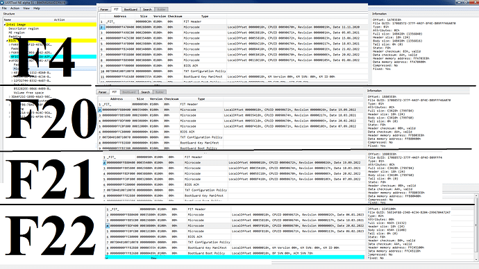
So I have opened the bios file (with the microcode I want to edit) into in UEFITool NE Alpha 51. I have opened every single section of the list and there is only one microcode file (and it matches the GUID(?) from the tutorial, so I’m sure I have the right thing. Per the tutorial, I right-clicked it and “extract body” and saved it as File_Raw_Microcode_body.raw.
The tutorial says to open the master microcode file in HxD editor, so I’m assuming that’s what this file is. I then have successfully opened it in HxD hex editor where I see all the hex values.

At this point I am the tutorial starts talking about a “CPU microcode repository” and I’m not sure whether that is even relevant to what I’m trying to do, which is to replace the newer bios microcode with the 0x104 microcode. ssIt also talks about checking whether the two microcode files are different sizes, and I’m supposed to be able to see this in the hex editor? I used the “fastforward” button in the data inspector window on the right in HxD, but I don’t see anything obvious indicating file size. Perhaps I am supposed to infer file size from the last offset line (which is 0014B400)? IT SEEMS I CAN CHECK THE SIZE IN UEFI TOOL… it gives “full size,” “header size,” and “body size,” and I’m not sure which is relevant.

Lastly, once I have both the new 0x104 microcode and the old microcode both open in HxD, how do I know what to replace? (I am currently trying to figure this out from these two tutorials:

[GUIDE] AMI INTEL CPU Microcode Update Guide)

I think I am supposed to replace certain hex values, but also I need to make sure everything “lines up” so that nothing else is pushed out of whack. Something I am very confused about is that the different bios version have different numbers of microcode addresses.
Please see this image:


(Duplicate image backup in case the other does not display large enough: https://imgur.com/rTYKQbI)

Please excuse my ignorance, I am not anything close to a programmer. I really appreciate your help!

Thank you.
“Some BIOS strings exceeds the maximum length”?

Unfortunatelly, I didn’t save the patched version in my cloud storage, so I have none to share.
Try using AMIBCP PRO.

Im no programmer also… but you lack severe understanding and advanced knowledge, so its very difficult and i have no time for extended lessons.

It could be easier for you using MMtool and replace on F22 with the F4 old mcodes extracted with MCextractor (Extracted folder), it may work as it is and you have Q-Flash to recover.
Do not use the older mcodes for other cpu’s, use the ones you need only.

Every mcode in their respective bios version has its own starting adress and length (length varies from mcode revisons), basically the new(old) mcode will have to be pasted in this block length using HEX manual editing.

But there is no download. The source is in the link is only a PDF file. I tried to google ‘AMIBCP Pro’, ’ ‘AMIBCP 5.14.0058’, etc. no success.

@Tad91
Since AMI doesn’t offer the AMIBCP tool for the customers, you cannot expect here a download link.
Nevertheless you will be able to find a link, if you do a Google search for “AMIBCP 5.02.0031” and choose the first of the offered options. Then you may have to scroll down.

I found nothing for the new AMIBCP Pro I was able to find older versions but none of them can open the BIOS. They all report something like: “Maximum number of strings exceeded.”

I have tested: 5.02.0031 and 5.02.0034.

@Tad91
A Forum like this one doesn’t offer a tool, which cannot be legally achieved by a private person.
What about asking the Company AMI? I am pretty sure, that AMI will be pleased about your request.

If you read my posts, you will see that I did not ask for a link to the tool, because I understand, that it cannot be legally obtained by anyone here, unless they work for a hardware manufacturer. In my first post, I was using a free tool (Aptio V UEFI Editor). You can see that in my screenshot. Then Sweet_Kitten points me to the AMIBCP Pro tool that nobody has access to, afaik. I have not seen any indication that someone claims they have the new AMIBCP Pro or have used it to edit a BIOS. An then you tell me to ask AMI.

I fully understand that the tool cannot be legally made available here. But I would like to know, which tools people are using to successfully mod Alder Lake/Alder Point BIOS ROMs.

Has anybody successfully used AMIBCP to mod a Z690 BIOS? And which version did you use? Or are people using free tools? I see in the screenshots, that they use AMIBCP to mod older BIOS versions (for Z390, etc.), but what about Z690?

I searched the forum for “Z690” and I see lots of requests for modding but all but one request are unfilled/unanswered. It makes me wonder, if anybody has even been able to mod a Z690 BIOS?

As you can see: unfilled request here, and here unfilled #2, another unfilled here.
I found one success here in which the BIOS options were confirmed unlocked/unhidden, but they didn’t say how they did it.

In the meantime, as I said in my first post, I hit a brick wall with trying to unlock hidden options using the free UEFI Editor tool. I don’t know if this is because I am doing something wrong, or if it is because of the custom menu that this BIOS has.

Another, more successful, avenue for me has been to completely ignore the BIOS setup and its options and instead to modify UEFI NVRAM variables. I hit another brick wall there because the varstores that I need to edit, are write protected. These are ‘Setup’, ‘AMITSESetup’, ‘PchSetup’ to name a few. My workaround for this is to edit NVRAM vars in the ROM image and then flash the image (instead of changing the variable directly in NVRAM from UEFI shell or in BIOS setup). Now, you can imagine that is not the most efficient workflow for testing but at least it works.

This way, I have been able to enable S0 power state (Modern Standby) by setting ‘Low Power S0 Idle Capability’ to enabled. It is disabled and hidden by default. I’m on Alder Point Desktop (Gigabyte Z690 Aorus Elite DDR4). Now it shows in Windows:

The following sleep states are available on this system:
    Standby (S0 Low Power Idle) Network Connected
...
The following sleep states are not available on this system:
    Standby (S3)
        This standby state is disabled when S0 low power idle is supported.
...

With stock BIOS, it is the other way around. S3 is available and S0 is unavailable.

There is yet another issue I need help with. In the process of doing this, I had to enter manufacturing mode, because I had issues with Gigabyte’s and AMI’s flash tools refusing to flash unsigned ROMs (or at least refusing to flash unsigned BIOS region only ROMs). I tried the old version of AFU flash (with the ‘/GAN’’ option but it cannot see the EC on Alder Point.). Now I need help with exiting manufacturing mode. Currently, I don’t have ‘Intel(R) Platform Monitoring Technology Device’ in device manager anymore and Intel’s MEInfo tool reports.

PS C:\CSME ADP v16.0 r8\MEInfo\WIN64> .\MEInfoWin64.exe -VERBOSE
Intel (R) ME Info Version: 16.0.15.1829
Copyright (C) 2005 - 2022, Intel Corporation. All rights reserved.

General FW Information
    FW Status Register1                          0x80042044
    FW Status Register2                          0x39284106
    FW Status Register3                          0x00000020
    FW Status Register4                          0x00004000
    FW Status Register5                          0x00000000
    FW Status Register6                          0x40200000

    Current FW State                             Disabled
    Flash Partition Table                        Valid
    FW Memory State                              CM0 with UMA
    FW Initialization                            Initializing
    BUP Loading state                            Success
    FW Error Code                                Disabled
    FW Mode Of Operation                         Unsecured mode by H/W jumper
    SPI Flash Log                                Not Present
    FW Loading Phase                             BringUp
    FW Loading Phase Status                      CM0_TEMP_DISABLE
    ME File System Corrupted                     No


Error 632: ME disabled.
PS C:\CSME ADP v16.0 r8\MEInfo\WIN64>

The problem with ’ FW Mode Of Operation : Unsecured mode by H/W jumper’ being of course, that the board does not have a hardware jumper. Currently, the only way that I know of to re-enable ME and to exit manufacturing mode is to flash the stock BIOS, but that defeats the purpose. I would like to keep the modded BIOS but exit manufacturing mode and re-enable Management Engine. Is the problem possibly, that I did not flash the entire ROM, but only the BIOS region?

So, what I need help with at this point is

  1. need help with unhiding BIOS settings
  2. I possibly also would like to be able to change setup/optimized defaults
  3. How can I exit manufacturing mode and re-initialize Management Engine (ME)?
  4. Lastly, How can I remove write protection from NVRAM vars that are write protected so that I can set them from UEFI shell? What is responsible for protecting UEFI vars, and how do I remove it? Is it a hidden BIOS setting perhaps (like “BIOS Lock”, Help: “Enable/Disable the PCH BIOS Lock Enable feature. Required to be enabled to ensure SMM protection of flash.”)? Or is it more deeply rooted? Perhaps in the flash descriptor?

I forgot to make clear, that this was an ironic advice.

Better go to “HACKPEDIA” or “MODPEDIA” its all there… we cant help you or any one else, besides what we know and what each individual user decides to share it or not, simple as the case you saw as solved and i know that that user doesnt like to share, perfectly understandable choice as he makes profit with it.

Do you realize that this is a user forum and their disposition/available time?
This is not a classroom and theres things that can be taught in a blink of an eye, neither is the forum responsible for tips and methods shared.
The forum shares users experiencies and new users will have to break through their own way.

Who told you that this all you describe is achievable with “mods” or even possible?
Do you realize that reverse engineering bios code is more that just a simple micro code or an EFI driver? Do you know why its a total risk for companies like AMI / Insyde to suffer an internal data and tools “leak” to public audience… compromising the global market of their clients?
Not all free tools, OEM bios code have the same results when we mess with it…
These free tools are mostly user own development… to achieve similiar functions but we cant expect that the results will be 100% substitute for official tools (Leaked )

My advice and this one is not ironic, is to get some more patience, keep digging and keep learning… as we all do.

1 Like

Thank you very much for taking the time to help me.

I have made some progress by following this guide from reddit

There were a few messages asking me how to do this 104 microcode trick. I shared it with one of the members and he successfully UV his 13700K. So I am sharing the procedures step by step.

  1. Go MSI website and download the similar version of B660M BIOS. If the board is available in DDR4 and DDR5 versions. Make sure you download the same version as your B760. For example, if you are using B760M Mortar DDR4, you should download B660M Mortar DDR4.
  2. The correct version is the one with the update log that states “- Ready for next-gen CPU.” dated Jul 2022.
  3. Download MMTool for editing BIOS.
  4. Click “load image”, select the B660 BIOS, choose “All files” as Files of type.
  5. Click on the tab “CPU patch”.
  6. You can see a line with microcode “03267104” and CPUID “0671”. Select that. In Patch file, type 104 and click “Extract a Patch Data” then Apply. A file named “104” should be available in your BIOS directory now.
  7. Download the latest version of BIOS for your B760. Repeat steps 4-5.
  8. You should see a line with microcode “0326710F” and CPUID “0671”. Select it and click “Delete a Patch Data”. Apply.
  9. DO NOT delete the line dated “2021/05/05”. Just delete the one mentioned above.
  10. Click “Browse”, select the 104 file that was extracted from step 6. Choose “Insert a Patch Data” and apply. You should now see a line with microcode “03267104” and CPUID “0671” is inserted.
  11. Click “save image”. The BIOS is good to go, you can flash it as usual.
  12. Enter BIOS, select “offset mode” for CPU voltage and set to “-0.005v”
  13. Download Throttlestop. Open FIVR, set both CPU voltage and cache voltage to your desired offset. My 13600KF can achieve -180 mv (run Benchmark at 1.12v) without any stability issue.
  14. Set up a scheduled task to run TS automatically when Windows starts up. Many websites provide guides on how to do it.
  15. If you are using Win 11, remember to turn off “memory isolation” in Windows security otherwise TS won’t work.
  16. Run Cinebench R23 to check stability and see if performance drops. Done.

Disclaimer: Flashing the BIOS incorrectly can lead to an unusable system. Flash the BIOS at your own risk.

Hi again,

I have one last question. Do you know if microcodes are the same between different board manufacturers? Say for example an MSI b660m ddr4 board and a Gigabyte b660m ddr4 board, both have microcode with the following similarities:

Microcode ID: 0026700E
Platform Type: 02
CPU ID: 0670
Update Revision: 0E
Date: 2022/02/20
Size: 00030800

Are these microcodes the same such as I could swap one in for the other and the bios would boot and work correctly? (This is just an example but the problem I’m facing is that I am supposed to track down a 0x104 microcode which for sure undervolts correctly, but my board earlier bios has a 0x105 microcode (which I think undervolts correctly but not totally sure) The 03267104 code is revision 04 and the 03267105 is revision 05 with a date of 4 months later. They are however the same size and same CPU ID. Can I use the 104 code from thee MSI board in place of my Gigabyte’s board 105 code? Intuition says probably, but obviously I would like to know if there is a way to compare the actual code that doesn’t involve me trying to manually read and compare thousands of hex characters. From on the the guides here, I remember that one concern is screwing up the “fit table” but in the program I am using right now (MMTool) I do not see a fit table.

Thank you.

Micro codes are universal and unique ID distributed from CPU manufacturers to OEMs.
They are implemented as they come and across several systems models but all the same across all motherboard manufacturers.
Revision 04 is the same to MSI or ASUS or ASROCK etc, no need to compare it.
These revisions are updated or not, when the motherboard manufacturer decides to update their bios product and release it public to the end users.

Thanks for the response! So I’m a bit confused, so Intel makes the code with constant revisions (they hand out 04 to mobo manufacturers, manufacturers release some boards with that code), then Intel does another revision (they hand out 05 to manufacturers, and manufacturers probably load up the new boards with 05 at that point), is that right?

So if I replace a microcode 03267105 (revision 05 - has about 20 extra lines of hex code compared to 04) with 03267104 (revision 04), do you think that would screw anything up?

I am using MMTool Apito - the process would be: open the bios file > click “CPU patch” to see individual microcodes > click on one I want to copy to the newer bios > click “extract patch data” > click apply
Then I open a new bios to the microcodes the same way > delete the 032671XX that is already there > “Insert a Patch Data” > choose “03267104” from old BIOS > apply > then flash the modded BIOS.

Thank you.

Usually the system can use all older mcode revisions of one CPU model, no hw harm will happen to the system/motherboard if it doesnt boot.
If it doesnt boot its related to CPU S-spec numbers and/or specific OEM board own code.