[GUIDE] Update CPU Microcode + Fix FIT Using UEFITool / Hex

Update CPU Microcode + Fix FIT Using UEFITool / Hex

This is a quick requested guide I put together for someone, on how to edit CPU microcoded with UEFITool and how to update/correct the FIT table in some BIOS.
There is already a guide here on how to update microcodes using these very same methods, which includes a brief section on correcting FIT table, but some users have asked for a little more info/guidance on how to do both of these things especially FIT corrections…

So here is my method of doing both of these edits, hopefully it will help fill in some gaps the other guide may leave for some users.
Mainly this guide will focus on correcting FIT table, since redoing microcodes via hex is tough to explain guide-wise and the above guide already does a better job than I can at explaining that aspect.
This guide applies mainly to modern Intel boards that contain a FIT table, if you do not see one in your BIOS with UEFITool NE Alpha, or you have AMD board, this guide will not be very helpful for you due to microcode edit section is not in-depth.

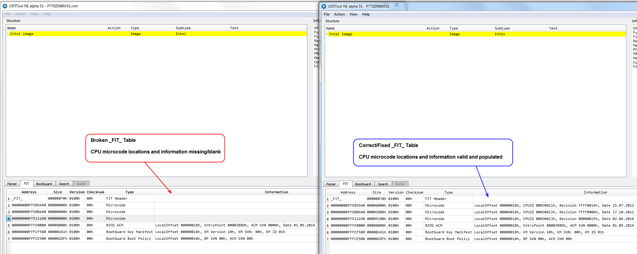
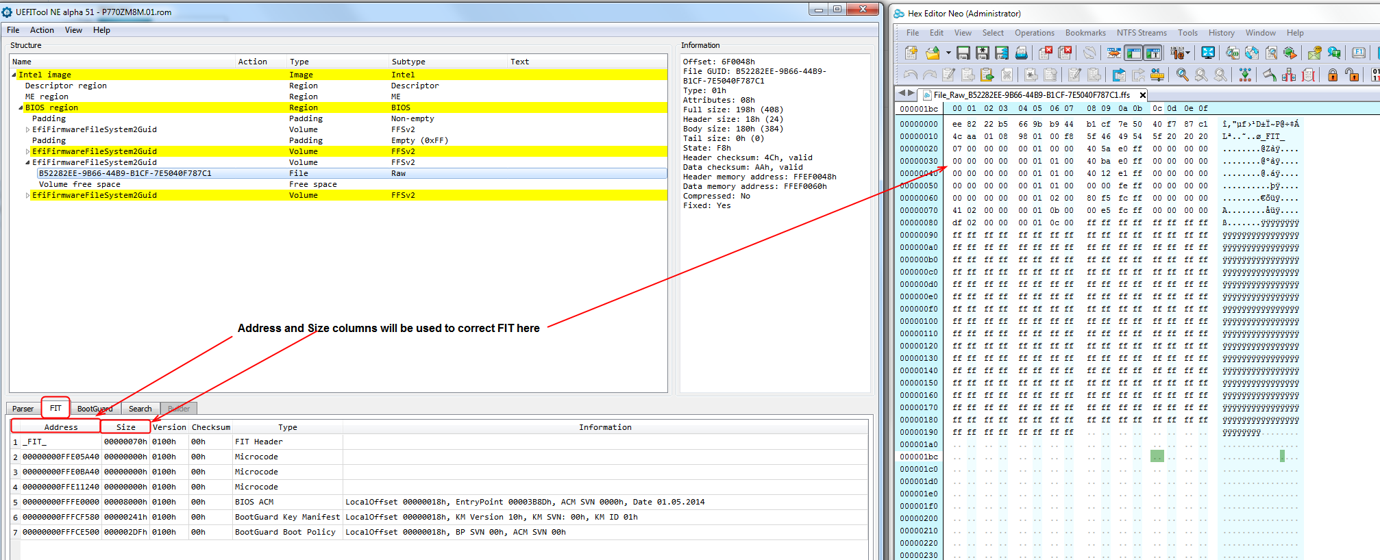
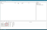
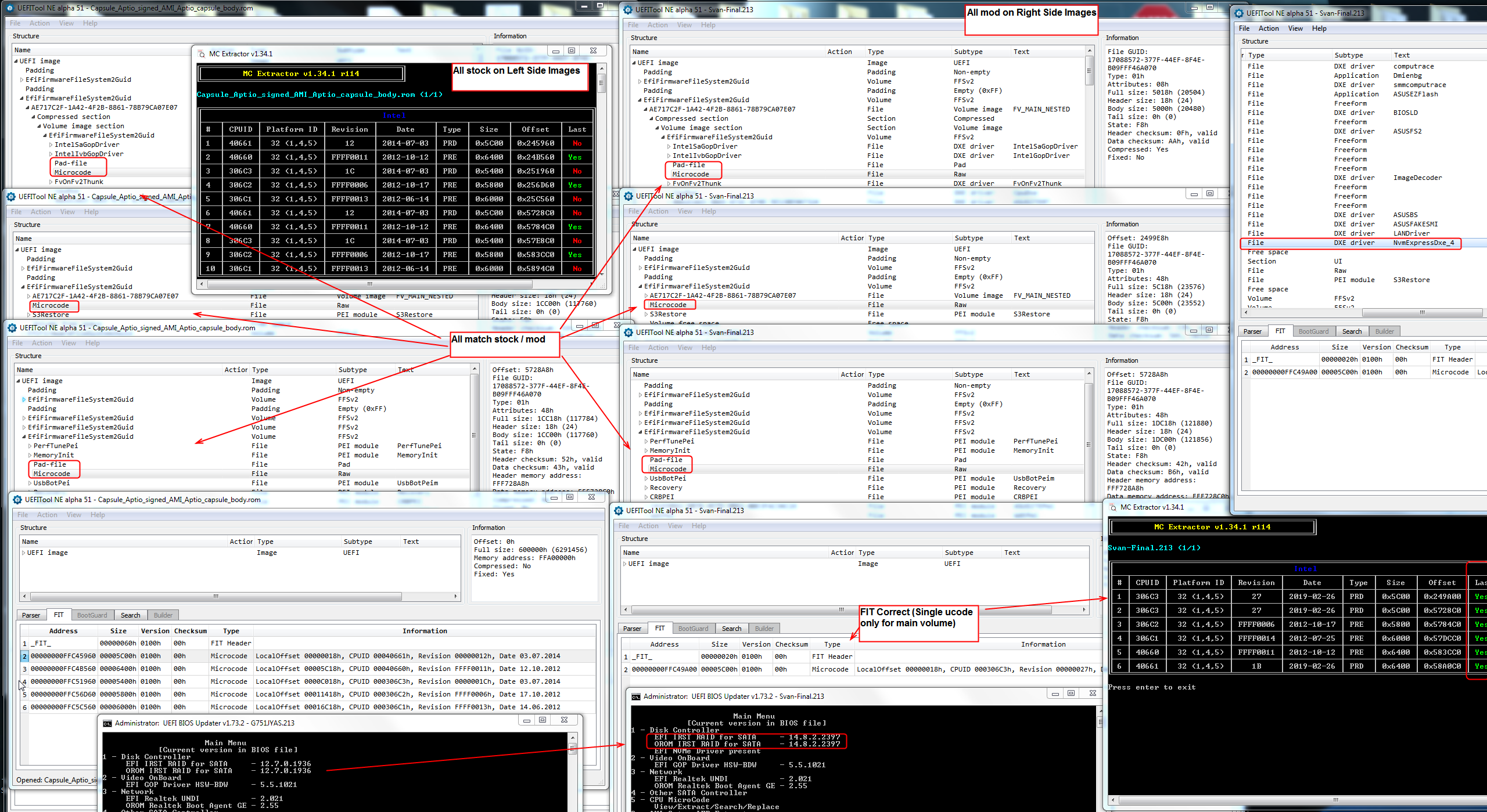
FIT table can be viewed here with UEFITool NE Alpha, example of invalid and valid FIT is show, if you are reading this guide please enlarge so will see how to immediately recognize the difference
If this is broken in your stock BIOS, that’s not how it’s supposed to be, this only means manufacturer was being lazy and didn’t notice or fix, or has poor BIOS coding skills Please fix this for yourself even if not modifying your BIOS otherwise

FIT-Broken-VS-Correct.png


Tools needed:
Both UEFITool & UEFITool NE Alpha
Hex editor of your choice, I use paid version of Hex Editor Neo they do have freeware version too, another good one many use is HxD Hex Editor
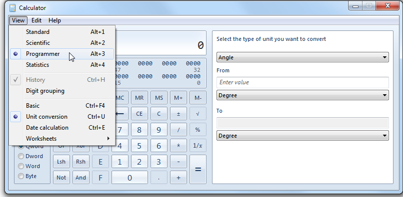
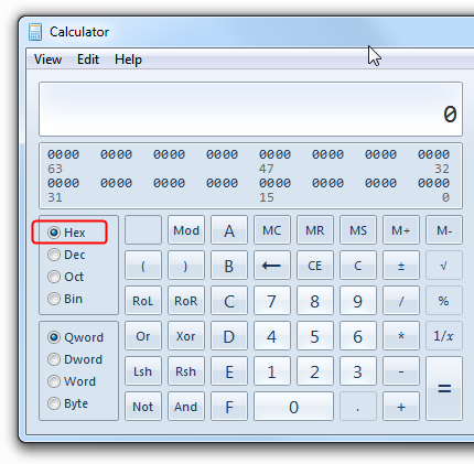
Standard built in windows calculator (Set to “Programmer Mode” with “Hex” selected on left), or any other hex capable calculator

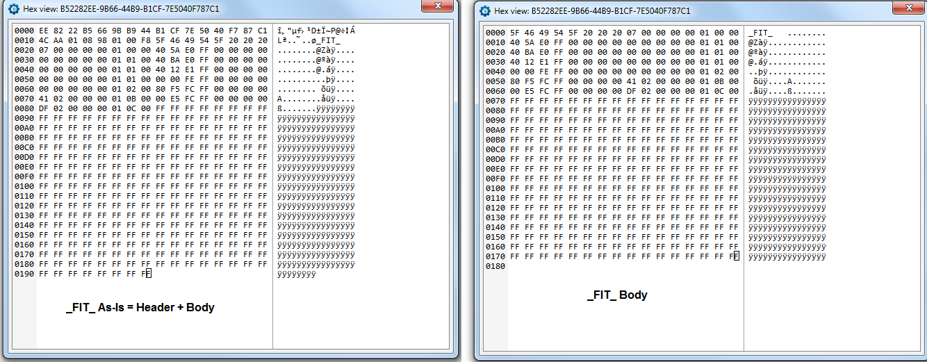
FIT Table is often (Maybe always?) at GUID - B52282EE-9B66-44B9-B1CF-7E5040F787C1
This contains the CPU microcode locations first called by the BIOS. Sometimes there is two actual locations (dual microcode files in seperate volumes), the FIT table only contains info to point the BIOS to the first microcode locations.
FIT table also sometimes includes locations to Intel BootGuard/ACM keys, hash and policy locations. The first entry is always the FIT header, this contains the GUID, header and data (body) checksum, type and attribute value, file size and state value.

FIT-Complete-Body.png

FIT-Info.png


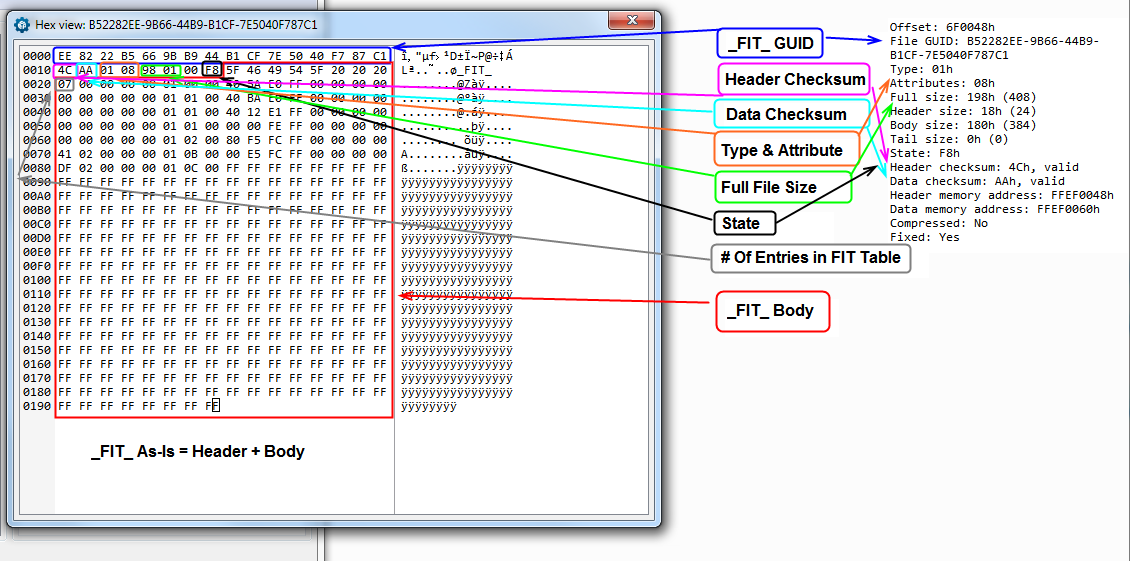
The body of the FIT file contains all the rest of the information mentioned previously, microcode locations and BootGuard/ACM keys, hash and policy file locations.

FIT-Body-Info.png


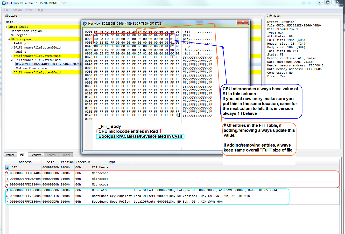
In the FIT body, the 8th or 9th byte is always the total count of entries in the FIT table, verify this against what you see in UEFITool FIT Tab count total, if incorrect it should be updated to actual value
This count includes the header, all CPU microcode entries, any additional but empty (not blank/incorrect) microcode locations, and the BootGuard/ACM keys, hash and policy file entries if present

When working with the FIT file, for the general purposes here, you only need to extract the "body", if you need to correct checksums post-edit that can be done in a seperate edit.
If checksum corrections are needed, they will usually be corrected by UEFITool upon saving, so you likely will never have to correct these or worry about that.

You can double click the FIT header in UEFITool tab to be taken to the FIT module in the BIOS, the same applies for CPU microcodes when there is at least one microcode entry still in the table (Sometimes when blank, you can still click empty address and get there).
If there is not, you will need to find the microcode modules via other means such as GUID Search or use UEFITool "Go To Address" and enter the incorrect address shown on the left side of the blank/broken microcode entry, usually that will still take you to the correct file containing the microcodes.


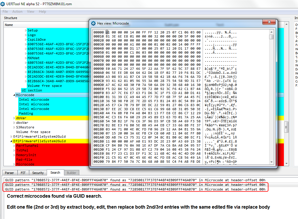
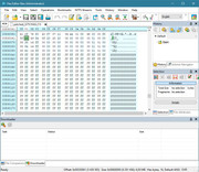
CPU Microcodes are often (maybe always?) at GUID - 17088572-377F-44EF-8F4E-B09FFF46A070

Three-Microcode-GUIDs.png


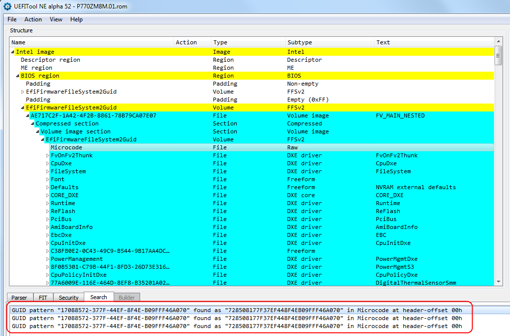
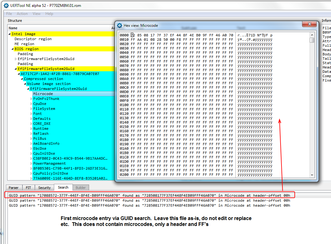
Sometimes you will find 2-3 x this GUID via search as seen in above image. In those instances check each one via hex view, when there is 3, usually the first one is not the file we want to edit, which you can recognize by it only containing a header and rest filled with FF’s.
We want to edit 2nd and/or 3rd entries, these contain the CPU microcodes. Each of those modules is a duplicate, so you can extract and edit one, but be sure to replace both with the updated file.
When updating microcodes via UEFITool extract using “Extract Body” and replace updated file via “Replace Body”

First-microcode-GUID-Wrong-DoNotEdit.png

2nd-3rd-Microcode-GUID-OK-EditOne-ReplaceBoth.png


Editing microcode file can be done two ways, whichever is easier for you to do. First way, simply make a new hex file and copy in the microcodes one after another into the file.
Second way is open the original and search for each old microcode file one by one, then replace with new version. The second way is only easy if old and new microcodes are the same size, otherwise you will need to move next one down/make room etc.
Personally, I find it’s much easier to make a new microcode file from scratch, that way you do not have to worry about or wrestle with files sizes and trying to figure out how/where things can fit or be moved to etc.

Always check the original microcode file to see if there is space (FF or 00) between microcode entries or not, sometimes there is and sometimes not. Sometimes you need to start each one at a certain offset, followed by FF’s up to the next one at certain offset.
I am not sure how to explain making these changes or choices on offset starting points, apologies to all! I’ve mainly only seen this matter on AMD, and some older Intel.
I think, usually offsets need to be multiplies of 800h or 1000h, but sometimes this is not correct either, and you’ll need to look at the original microcode file raw with MC Extractor and guess based on how the old offsets looked.

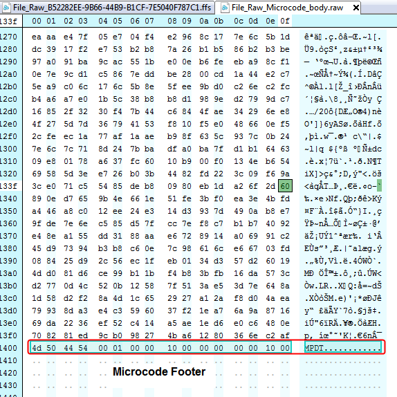
Also always check the last line of any microcode file you edit, sometimes there is a footer, and this needs to remain in place, or be added back in when done or when creating your own new file from scratch.

Microcode-Footer.png


And as mentioned previously, there is already a guide for updating microcodes via hex here on the forums, that should guide you along best if you need help in hex edit copy/paste etc
[GUIDE] AMI INTEL CPU Microcode Update Guide


Fixing the FIT Table

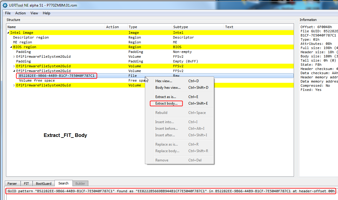
1. Open your BIOS file in UEFITool NE Alpha, Drag and drop to open is possible >> Locate FIT via searching for GUID B52282EE-9B66-44B9-B1CF-7E5040F787C1, or by double clicking FIT header in FIT tab, extract body.
Apologies for the possibly confusing image below, I’ve extracted “As-is” for this guide, even though I will not be making any header changes, so header will be visible in all hex images as well, apologies in advance!

Extract-FIT-Body.png


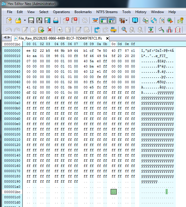
2. Open FIT file in hex editor >> File_Raw_B52282EE-9B66-44B9-B1CF-7E5040F787C1.ffs file or File_Raw_B52282EE-9B66-44B9-B1CF-7E5040F787C1_body.raw if you extracted body

FIT-Open-Hex.png


3. Go back to opened BIOS in UEFITool NE, and navigate to the FIT Tab, we’ll use “Size” and “Address” info from here in next steps.
If you have room on monitor, open hex and UEFITool side-by-side for easier workspace

FIT-Tab-Side-By-Hex.png


4. Open windows calculator, and in top section open "View" menu and choose "Programmer", then on left side ensure "Hex" is selected

Windows-Calc-Programmer.png

Windows-Calc-Hex.png


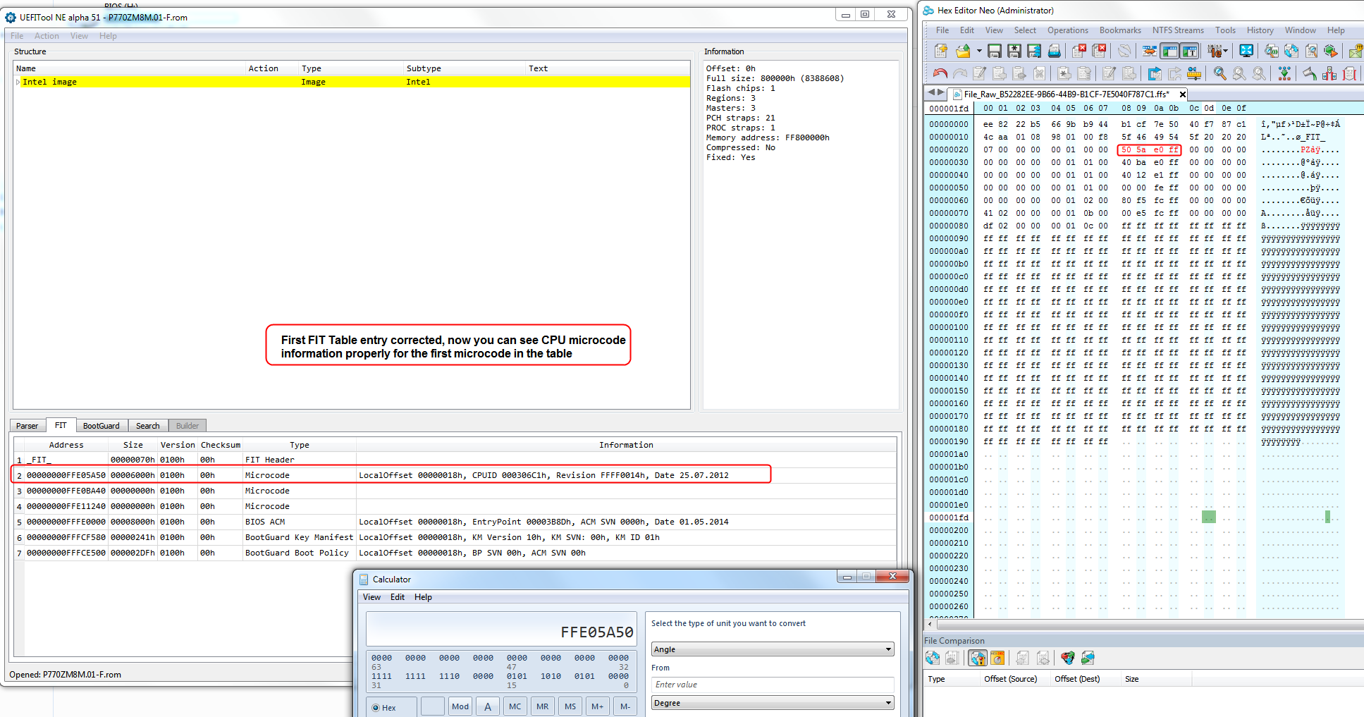
5. Locate the first microcode entry in hex file, and UEFITool NE - this value we change first, in order to be able to start adding the rest of the locations and sizes

FIT-First-Addy.png


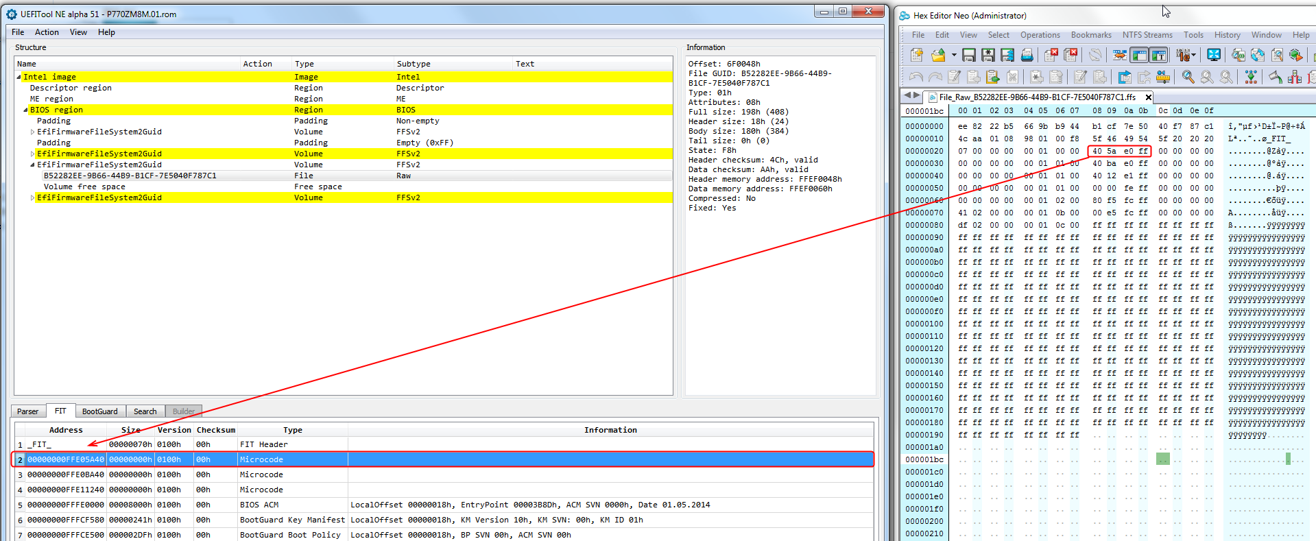
6. In UEFITool NE locate the first actual “microcode containing” GUID 17088572-377F-44EF-8F4E-B09FFF46A070. If there is only one entry for your BIOS when searching for 17088572-377F-44EF-8F4E-B09FFF46A070, that is the file you want here, if there is 2-3, usually second one
Double click the entry in search results at bottom so you are taken to the files location, then click on it to be sure it’s selected. On the right info area, we need value from “Data Memory Address” This is start of the first microcode, highlight and copy value

FIT-First-uCode-Addy-Value.png


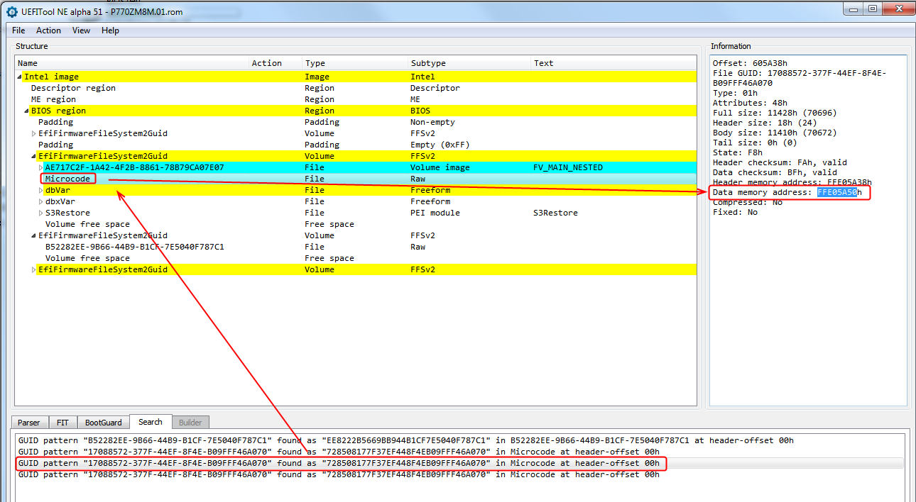
7. In calculator paste or enter the first microcodes “Data Memory Address” found at above step, we’ll do nothing more in calculator for this step, leaving this value to add onto in next few steps

Calc-Paste-First.png


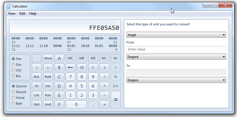
8. In hex editor, we’ll now correct the first CPU microcode entry in the FIT Table. These values are stored in reverse order, for example this means that a value of FFE05A50 is stored in the FIT table as 505AE0FF
Edit in your first value, from step #6 in hex editor at the first microcode entry line, I reverse order as mentioned above

FIT-First-Entry-Edit.png


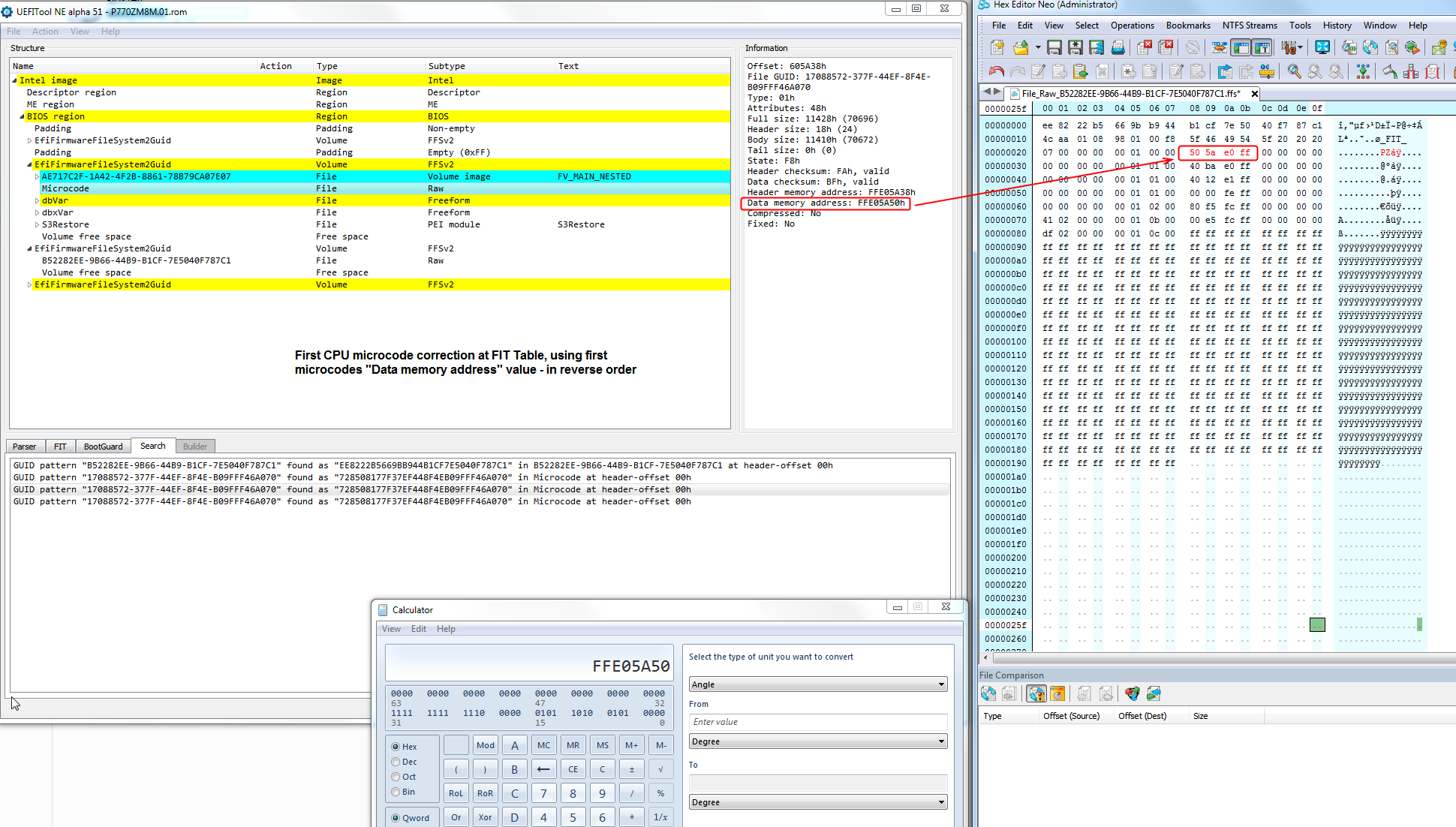
9. Save the file in hex, either save as is, or save a copy noted as “Modified” etc. This process will be repeated several more times, with added step for each additional microcode, then saved and re-inserted after each edit.
Once you become more familiar with the process, you can edit all at once after the first entry is saved and entered, because you will be able to skips steps due to knowing previous and next microcodes size and thus the next ones location/address.
You will be able to correct each subsequent microcode address by adding previous microcode’s size to get next address, hard to explain but you’ll see what I mean after doing this a few times and are familiarized.

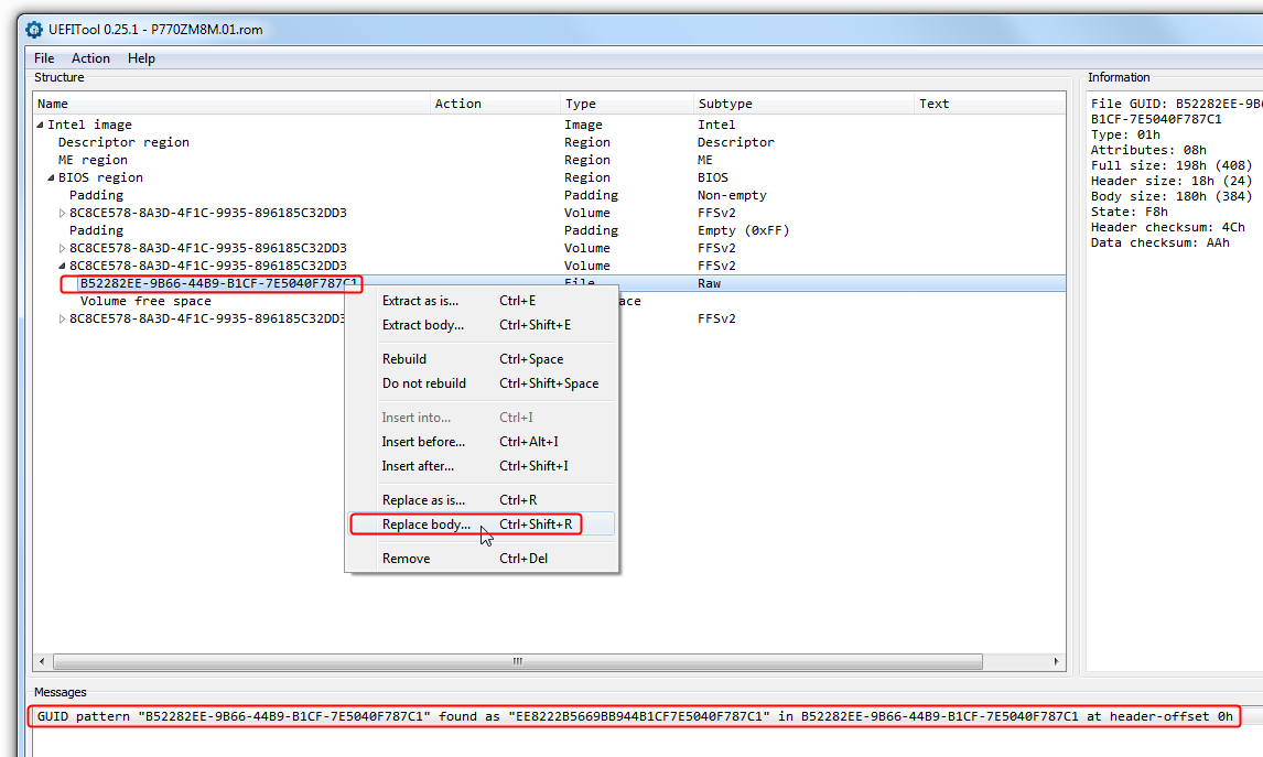
10. Open BIOS in regular UEFITool, then search for FIT at GUID >> B52282EE-9B66-44B9-B1CF-7E5040F787C1 and replace “Body” or “As-Is” depending on how you originally extracted
Then save BIOS image, as a modified file so you know which is original and which is modified. When asked if you want to open modified file, say yes and leave open, you will come back several more times to reinsert FIT module.

FIT-UEFIToolReg-ReplaceFIT1.png


11. Open modified BIOS again in UEFITool NE Alpha, go to the FIT Tab, and see now there is corrected entry for the first CPU microcode

FIT-First-Fixed-Done.png


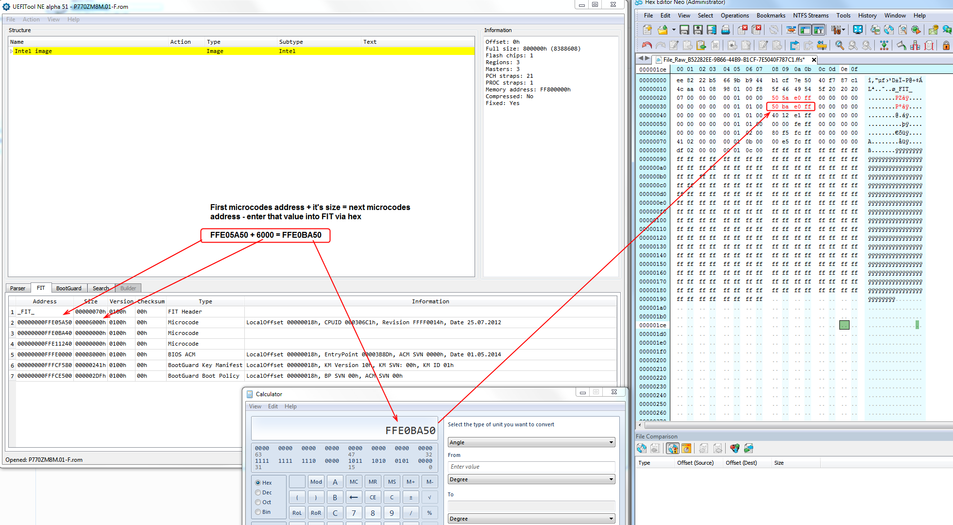
12. Now, open your modified FIT file again in hex, if not already left open, now we will fix second entry. To fix each subsequent entry all you do is enter the previous microcode’s starting address into the calculator, then add it’s size.
The result is the next CPU microcodes address value that you will put into FIT via hex, as you did in step #8 So for this guide, we’ll add FFE05A50 + value seen in the “Size” column for this microcodes entry which is 6000 (So FFE05A50 + 6000 = FFE0BA50)
This value FFE0BA50 will be entered in FIT file via hex, this will be the starting address of the next microcode. Once completed with this step, then see steps 8-9-10-11 again

FIT-Second-Entry-Edit.png


Updating each subsequent microcode entry will be this step + steps 8-9-10-11 again each time, checking to be sure everything looks correct and updates each entry as you go
As mentioned on step #9 once you become more familiar with the process you will be able to skip steps, but it takes a while and sometimes there will be mistakes you need to go back and fix.
If one entry is off, all the following will be off and will remain blank until the first missing entry is corrected.

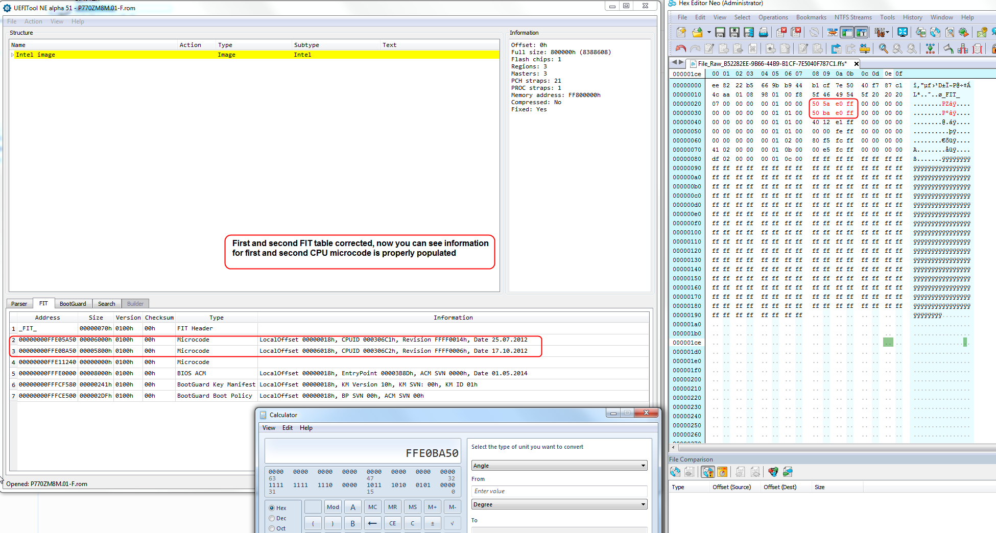
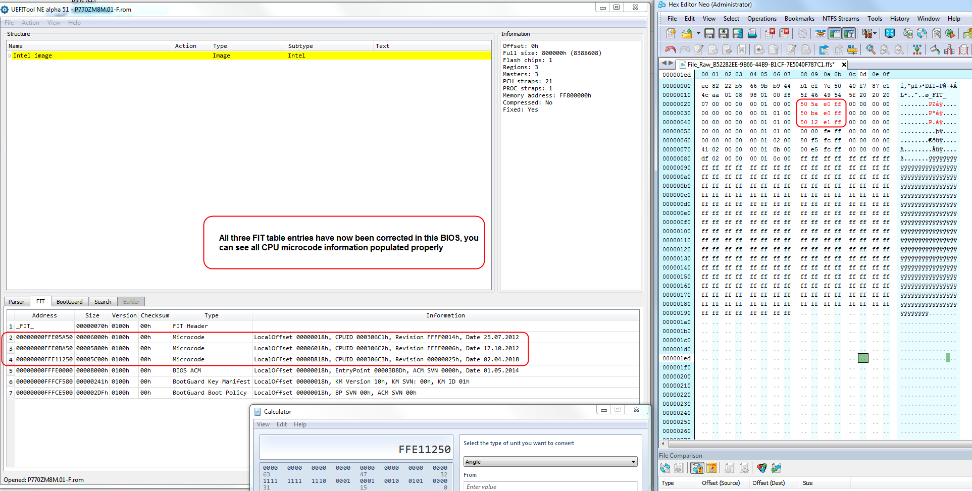
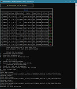
13. Repeat step #11, see second entry is now corrected, repeat steps 8-9-10-11 as many times as microcodes your BIOS has. You can view how many microcodes your BIOS has by dropping BIOS onto MC Extractor
Only a single microcode volume is used here, if your BIOS has duplicated microcode volumes only first one applies for this process. Meaning if you see set of duplicated CPU microcodes in MC Extractor or MMTool/AMIBCP etc, only the first set is used here.

FIT-Second-Fixed-Done.png

FIT-Third-Fixed-Done.png


Hope this helps some of my fellow BIOS modders!
If you have any questions, or need me to add any additional step/process please feel free to let me know, thanks!

3 Likes

This is the additional and in-depth information I have been looking for so thank you! Great guide!

Appreciate the feedback and I’m glad it’s going to be helpful to others, thanks!

I can’t thank you enough for this wonderful and well-explained guide. It is going to be very very helpful. Thank you so much!! :slight_smile:

I will try out the steps in the guide and come up with the queries if there are any.

Thank you too, I’m glad it’s looking to be useful and detailed enough to help others, I was worried it may not have enough details for everyone to follow along easily.
If more steps or explanation is needed on something let me know and I’ll try to add in to improve it!

Good luck fixing your FIT Tables!

thanks you sir HP 650 G3 origenl bios erasse but new bios error
hp manufacture programming mode is in unlock
so fixing my issue

@ABDUL_REHMNA - You’re welcome! If you need help let me know.
This can now be done easier with UEFITool NE 55, using microcode “header address” it gives you for each individual microcode (no math needed now). I just haven’t had a chance to update this guide yet

Hi, first thanx for this great tutorial. I know making them take a lot of time.

Before showing my problem, I would like to say that extracting body part seems a bit to much as you can directly edit the bios in Hex editor and search for the “FIT” entry.

Rog Asus G751JY - Bios v213 - CPUID 306C3

First showing some pictures :


I understood well to reduce number 06 to 04 to remove the empty modules lines deleted by the microcodes update in UBU. I tested and the 2 empty lines disappear.

For info i have only one “FIT” entry in hex editor. The big trouble I have is that following your tutorial as you can see my “FIT” values are on left side in the hex editor.
The microcodes update size are all at 0 in UEFITool (microcodes hexadecimal values seems ok)

Do you think I need to update microcodes manually from scratch ? And I got a special question that if I updated RST and OROM RST in UBU do I need to check something about size or else ?


Update : Just tested with only microcodes updates in UBU and the result is much better. Patching RST and Orom RST in UBU and I am back to same problems earlier.
Just tested original bios with only RST patch in UBU that’s the matter will report to @Sonix

@Svan - extracting FIT body is best, some BIOS need the module or entire volume rebuilt to correct checksums, so easiest and best practice to do it that way (same applies to microcodes in most cases too).

There is usually only one FIT, sometimes more may be detected or false, or left in by poor BIOS engineer work. However, there is often multiple microcode volumes, and in those cases not all always need to be or should be updated, only the ones that actually contain microcodes.

I do not see the issue in your “update” image, please circle what you are referring to about microcode sizes, all looks OK to me

UBU can usually update RST easily, but you should check all padding files before/after and make sure they match in BIOS before and after edit. This is mainly above/below any/all microcode volumes (even if you are not touching microcodes), and at the end area of each volume
If you see missing pad or non-UEFI files from before/after edit with UBU don’t flash that BIOS, have someone check the mod for you.

@Lost_N_BIOS

Would be great if you can check the bios for me :

What i did from original bios :

- Updated MC and RST in UBU
- Edit bios in hex to modify the FIT hex number referencing the number of lines (06 to 04)
- Edit in MMTool 5.0.0.7 : removed all modules from CMSCORE (Vol. 02:01-00) bottom to top include Ip6Dxe to replace it with NvmExpressDxe_4 and resinserted all removed modules to same order.

Thanx in advance

@Svan - I don’t use MMTool unless I am forced to do so, so am not 100% familiar with checking those edits for possible issues due to that method of editing.
However, I do know how to use MMTool to make those edits in CSMCore, and would not do it how you mentioned, so I do wonder why you did all that extract and replace same module stuff (unnecessary for a CSMCore edit)?
Also, I’m also curious why did you insert the NVME into CMSCore anyway, I’ve never seen this suggested or used in any editing guide?
BIOS is Aptio IV, so V5 shouldn’t be used, unless some issue with IV causing failure to edit and even then possibly best to find the reason first before using V5

NVME insert looks “OK”, but I only checked with UBU scan. I would not do that edit the way you did, so I don’t really know how to see if it causes any issues doing that.
All that needs done is insert the NVME into the main DXE volume, however you do it, unless you run into some reason you can’t then other workarounds could be explored.

I am still waiting for your answer/info on what you considered the “issue” to be in your “update” image above? I do now see the two extra entries you said you removed since you mentioned this, I didn’t notice this before, is that what you meant?
That’s not correct FIT edit, you need to correct the count and FF out those two extra lines if you are removing them, this wont cause boot failure but it’s best to do it correctly. I see you did this in BIOS at post #10, but then never fixed the microcode info.

I checked the attached file in post #10 and see several issues, first FIT has only three microcode entries and all are blank (So broken FIT). Padding file missing above last microcode volume (= bricked BIOS if flashed usually)
NVME should not be inserted into CMSCore. File is not back inside capsule, but this only matters/depends on how you planned to flash it.
Summary, that BIOS is broken in several ways, I would not suggest flashing it.

Do you want me to do this mod for you? If yes, please let me know how you are flashing the mod BIOS.
Also, please let me know if you want all microcodes updated and kept as in the original, or some removed and only the three you have in the mod now?

* Edit, I checked, and I see why everything is breaking here, due to limited size and the NVME module. Either special dance (involved/advanced manual edit) needs to be done to insert NVME properly.
UEFITool 25, MMTool 4.5, 5.07, 5.02 all break the BIOS and add a padding file when doing the proper NVME insert (at end of main DXE volume, below “LAN Driver”).
So, special dance required, I inserted tiny microcode body into this volume w/ single ucode, remove some other module temporarily for added space, insert NVME, rebuild, then put back in removed module, rebuild, then put back in correct updated microcodes, then fix FIT = all done correctly.
Similar issues caused by editing CSMCore with UBU or MMTool too probably, I didn’t check to confirm, same special dance used for insertion/correct updates on those to avoid similar issues mentioned above too.

Please wait if you’re reading now, wrapping up mod and will edit it in here shortly

* Edit 2 - @Svan - Here, EFI RST 14.8.2.2397 + oROM RST 14.8.2.2397 TRIM Mod by me + All microcodes updated + NVME Mod - Wow, that’s a fiasco to edit properly! Mainly due to the limited 4.68MB space in the main BIOS volume
In the end, I did not update all original microcodes in the main volume, in order to have enough space. I only inserted the one for your current CPU in the main ucode volume (So update to stock BIOS first if you get different CPU later)

So final mod = EFI RST 14.8.2.2397 + oROM RST 14.8.2.2397 TRIM Mod by me + NVME Mod + all microcodes removed in main volume except updated 306C3, all original microcodes remain in secondary (last) volume updated
1. EFI RST 14.8.2.2397
2. oROM RST 14.8.2.2397 TRIM Mod by Lost_N_BIOS
3. NVME Mod Insert
4. All microcodes removed in main volume except updated 306C3
5. All original microcodes remain in secondary (last) volume >> updated

ModFinal.png

Asus G751JY AS213-Mod_UPD.zip (2.7 MB)

@Lost_N_BIOS

Your are genius. Thanx a million times. I wish to have your knowledge I will flash it soon and report in this post.

I received my CH314a spi programmer (Will only use it for the G703VI).

I will contact you in private in some days for my G703VI. I wish to update only the Intel RST (Thinking know that updating MC is maybe useless since I will never update the processor for both laptops)

Thanx a lot again. Wish you a great day

Thanx so much.

Thank you, and you’re welcome too!

Since that was such a tough mod, and you have programmer, best to make a backup of this board too before you flash anything (and let me confirm it’s OK BIOS backup)
That way if anything goes wrong you are ready, in advance!

On the G703VI, we can update whatever you want, ucodes, RST, unlock BIOS menus etc

You have a great day too, and you’re welcome once again!

@ Lost_N_BIOS

I did backup with AFUDOS. I read somewhere that you got same backup with a programmer.

I flashed it with AFUDOS /GAN everything working 100%. Just got windows working a bit at boot like installing a new windows. Make me scared, but everything fine.
Need to wait to modify the setup for the G703VI to get the Pcie SSD inside then I will tranfer it to the G751JY.

Thanx again keep you updated.

AFUDOS may or may not give you complete BIOS backup, that would have to be looked at in BIOS tool to confirm, often it can’t access all regions. Best to do it with programmer since you have one.

Ohh, I see you already pushed ahead So, now it’s installed, did you check all things are actually updated in BIOS on the board now? Check current in-use microcode with HWINFO64 or AIDA64, RAID Roms you’d have to dump BIOS and then scan with UBU to confirm that (This also check NVME while you’re there too)
I mention to check all this, because sometimes AFU and or AFU w/ use of /GAN can appear to flash but actually flash nothing.

You can disable post audio and animated logo if you want, once you have unlocked BIOS Or, it can be done via single settings changes using grub and setup_var, without a BIOS mod.

@Lost_N_BIOS

I did a backup with AFUDOS from your flashed bios. In UBU i got this (looks great) :


I will restore later the original bios (without capsule) and dump it with the programmer but first I need to set up the G703VI.

Just for info i found this : HWiNFO and Microcode and I don’t know where to check in there to much options even in AIDA64

Animated logo is not a matter got all options to disable them in bios and sound too. I discovered I see Intel logo at boot only when CSM is enabled.

For the G03VI (APTIO V) the best is to give you the dump from the programmer ?

@Svan - looks good then, that all looks like exact edits I did for you!

Here’s the three places where you see current “in-use” microcode with AIDA64 and HWINFO64 (two places, one in small CPU-z like window and one in the large AIDA64-like window)

AIDA-HWINFo-uCode.png


For the G03VI is this AMD or Intel CPU system? Anyway, yes, go ahead and lets dump, that way you get familiar with using that, how it works on your system, and so you can find which version software works with that system too.
That way if recovery is needed then you have a valid backup already made and know what works and how etc

@Lost_N_BIOS

Hi, here is the pictures I got in HWINFO got 27h in AIDA64 :


Will try the dump today. Cheers.

@Svan - Great, then it’s as it looked, mod BIOS flashed in fully and is working fine
Start a thread for your other system, about the dump, and put all the details there especially chip ID, and I’ll try to help you on it.
In regard to your 1, 2, 3 choices in PM, I forgot to reply. You can often just dump BIOS region via FPT and edit then reflash too, if it’s an Intel system.


Can you help me modding my Bios ? Check the PM please.