According to the supported chip list on flashrom.org, it should work, though SPI programming of it is listed as "The feature is untested but believed to be working"
And as you have seen, you would have to use either a resistor in series from the Raspberry, or different supply to get ~1.8V.
As for the AFU switches, i’m not sure what you mean, if they are the same? or if there are equivalent switches in Flashrom?
not sure about what some of the ones you wrote do, maybe someone else nows more about that.
I was trying to update the bios and instead of running the proper command: “AFUWINx64.EXE image /P /B /REBOOT /egm:npslp” I only went with “AFUWINx64.EXE image”.
/P stands for Program Main Bios, /B for program Boot Block
/EGM:npslp (NPSLP - No Preserve SLP2.0 Key) Engineering Mode
I’m not sure if just writing the image is enough, with flashrom, so I may have to add some extra parameters. In the meantime I’m trying to get someone with the same device (Gigabyte Brix 2807) to make a copy of the bios with flashrom, maybe that will not need extra parameters.
Yes, one thing to be aware of though, if flashing a dumped image from Another computer,
is that it may contain system specific information, such as MAC, serial number and so on, i don’t know if your specific HW, but still might be good to check Before flashing.
A person who pretty much Everything about BIOSes is Coderush, if any uncertainties about the BIOS image, you could try asking him.
Just repeating my answer to a PM here:
1. No “end user selling” vendors other then ASUS are adding board-specific data to their BIOS images, so if your board is not made by ASUS - you just need to transfer any data. The one major exclusion is an OEM product key for Windows 8 stored in notebook BIOSes, but it’s a different story.
2. For Intel-based systems with a single SPI flash chip (there are some dual chip configurations, but they aren’t popular) you need an image that starts with Descriptor region and has ME and BIOS regions. There can be additional GbE and PDR regions, but they aren’t required. AMD doesn’t use Descriptor, so don’t bother about this of your system is AMD-based.
3. The resulting image must have the exact size that the SPI chip has, so you need to stip the image down from any capsule headers and other stuff like this, if it’s bigger. If, on the other hand, it’s smaller for a megabyte or two - it’s not a full image, but only a copy of BIOS region, and you need a full BIOS dump from the same board to reconstruct your full image. In this particular case, BAYAP.F4 is a full flash image ready to be flashed in SPI chip, you don’t need to make any modification.
4. To interface 1.8V SPI chip with Raspberry Pi you need a 4 channel bi-directional logic level shifter like this one and a reliable 1.8V power source, otherwise your SPI chip will be dead in 3 seconds after you connect it to 3.3V GPIO pins of RPi. Some SPI programmers can autodetect SPI chip’s operation voltage, but they cost from $200 and up and a converter costs about $5.
Oh crap, thanks very much for adding this info!
I completley overlooked the signal level issue ![]()
Thanks for the info, I was preparing my back-up plan in case the RMA way doesn’t work. If it comes down to flashing, I think I’m going to buy a Bus Pirate, it seems a bit more advanced and I don’t want to unsolder the chip. Cheers
Hi, I’ve done some experiments (ASUS S56CM / K56CM Bios Modding - I’m doing this right?) and I’ve used this fantastic guide to recover my bios. I have some changes to propose:
Optional pre-pre-install:
1
2
3
2
3
#Maybe an update will be nice
sudo apt-get update
sudo apt-get upgrade
Pre-install:
1
sudo apt-get install subversion pciutils-dev
Flashrom install/update script:
WARNING: This script create and delete a directory named "flashrom" form the directory where you use these commands. You have been warned! It's not my fault if you lose your only copy of the work of your life that you saved in your raspberry under a directory named "flashrom".
1
2
3
4
5
6
7
8
9
10
11
12
13
14
2
3
4
5
6
7
8
9
10
11
12
13
14
#This command delete old flashrom sources downloaded in this directory from you or prevoius run of the script
rm -rf ./flashrom
#Download the last version of flashrom
svn co svn://flashrom.org/flashrom/trunk flashrom
#Go in the sources directory
cd flashrom
#Compile
make
#Install
sudo make install
#Return in the previous directory
cd ..
#Delete the sources directory
rm -rf ./flashrom
Before reading/writing the chip:
1
sudo flashrom -V -p linux_spi:dev=/dev/spidev0.0
This command will only probe for flash chips, without read or write anything. In this way you will know the chip that you motherboard use.
You can check the chips compatiblity here: http://flashrom.org/Supported_hardware
But why I told you to use this command? flashrom work also without it... yes and no...
If you know what chips you have you can add "-c <chipname>" when you read/write your chip.
I've a "W25Q64.V" chip so my write command become:
1
sudo flashrom -w /tmp/1.rom -V -p linux_spi:dev=/dev/spidev0.0 -c W25Q64.V
This also applies for read ("-r"), erese ("-E"), verify ("-v") and every other command that require to read or wirte the chip.
So this is how, but why I shoould use this information?
1) Is faster If you have to do this multiple times, flashrom will try to probe for chips only with the chip name given.
2) I've experienced some problems. If I do not specify the chip name, the automatic verify after every write will return "fasle" expected value errors. Flashrom think that the write is gone wrong somewhere but actually it's ok. In fact if I verify ("-v" option instead of "-w") , after the write command (with "false" errors), it's everything ok.
This command actually do not change anything, but will save you from "small heart attack" and question like "oh god why my raspberry won't write correctly? I've to trash my motherboard?"
And also, this sounds very very to much, but if you have time you can follow my rule:
- Completely shutdown the raspberry after every flashrom command. Just to be sure that there are no interferences/problems between a command and another.
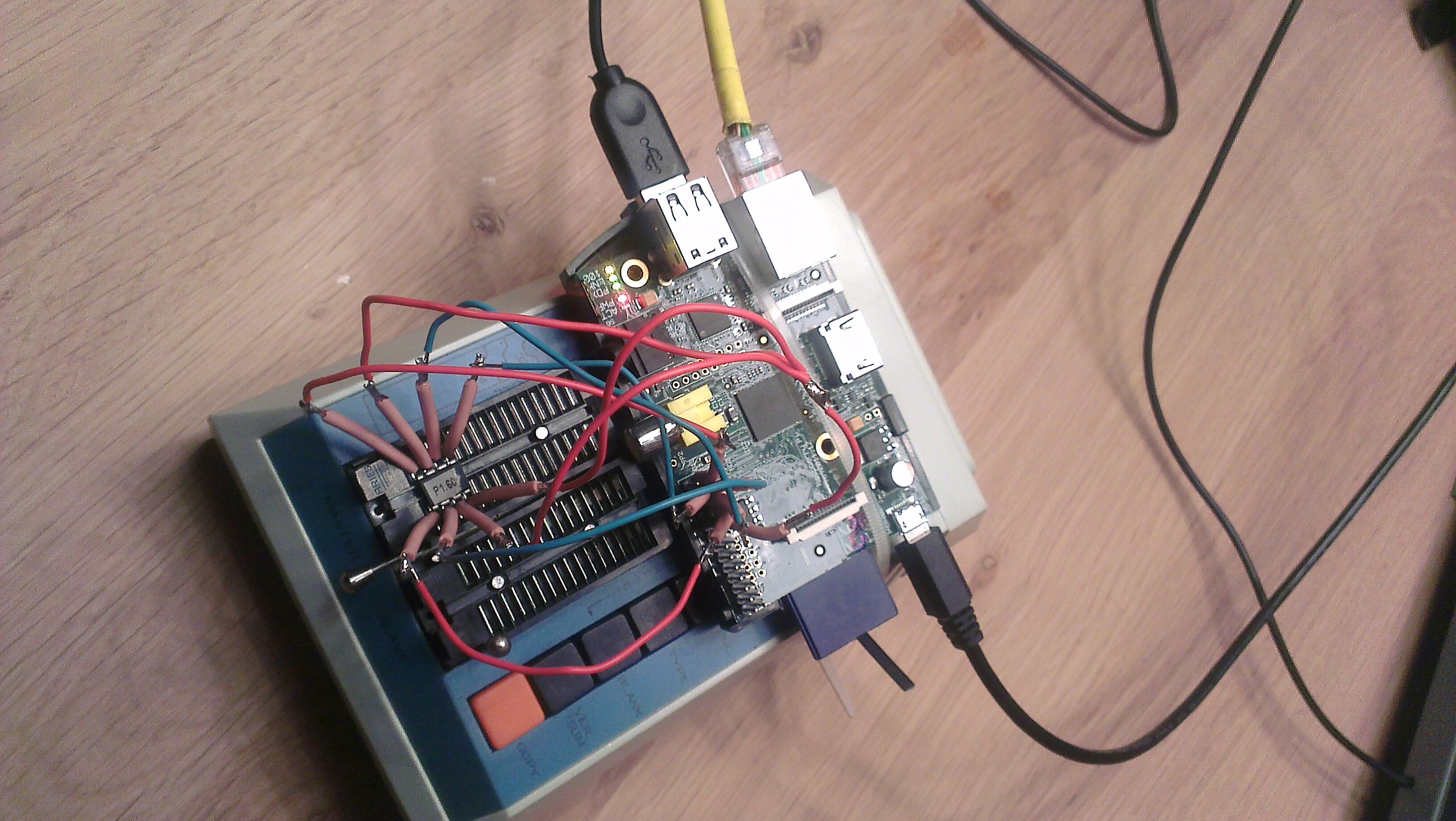
And also, if you do not want to remove/replace your bios chip or solder wires directly on your motherboard (like I did, it was a pain), you can buy this: http://www.amazon.com/ZJchao-xFF08-socket-adpter-programmer/dp/B00HIBKVYO you can also find it for lower price ![]()
This connectors do not work for every chip! Your chip may have different shape, dimension, pin… Find the correct clips for your chip.
Some images: (click on the link to view more images and details)

@Vento
Thank you very much for the input and good ideas to improve this guide, and great to hear that you found it helpful ![]()
I will make an updated version of this guide, with yours and other peoples findings as soon as possible.
Unfortunately i have had very little time to use the Raspberry myself since i wrote the guide, so it is great to get some feedback that can keep the guide up to date.
As CodeRush said, to recover my ultrabook (S56CM/K56CM from ASUS) I had to use my full dump! I’ve use fptw.exe in this simply way:
1
fptw.exe -D DUMP.ROM
When you open it with UEFITool the result should look like this:
Just look at the structure "Intel Image" (with BIOS region an some others), the numbers at the right may be different

Keep in mind that your board may be totally different, without this structure and/or fptw.exe may not work. Again, follow CodeRush's words
[quote="CodeRush, post:24, topic:30264"] ...
2. For Intel-based systems with a single SPI flash chip (there are some dual chip configurations, but they aren't popular) you need an image that starts with Descriptor region and has ME and BIOS regions. There can be additional GbE and PDR regions, but they aren't required.
...
[/quote]
Just some info about the update of this guide,
i am working on a complete update, but it may take a few Days Before it is done, as i want to verify every step to avoid any errors.
Pacman,
I am so grateful for your perfect post !!! You’re my hero!
Honestly, I was dealing with a mobo flash gone bad just after the ‘flash erase stage’ … on a brand new pc (of my father inlaw!)
Anyways, I was going to call the manufacturer for a new chip, when I started thinking ‘wouldn’t Arduino’s and RPi’s be fit to flash Roms?’
That’s where your post came up in my google query.
Since the flash rom chip was already erased I figured I give it a try, not hoping for much except another ‘experience’ with Linux and the Rpi.
However, suprisingly everything you wrote went perfect without any flaw. Checked the chip compatibility with Flashrom and when it was listed I got excited.
I did neglect your advice for the resistors and capacitor, I didn’t had those around and I read somewhere else how they just hooked the Flash rom up to the Rpi and flashed it, so I was willing to give that a shot.
RPI saving a new ASROCK 980DE3 MOBO! (yeahhh).
Many thanx and kudos to you!
Currently I’m working on an Arduino ‘Open energy monitoring’ home project. Let me know if you’re interested building one yourself and I’ll help you (if needed). I owe you that much. ![]() (http://openenergymonitor.org/emon/)
(http://openenergymonitor.org/emon/)
Kind regards,
Vernon
@ Hutas:
Welcome at Win-RAID Forum and thanks for your report.
We are glad, that you were able to successfully reanimate your mainboard by following Pacman’s guide.
Enjoy your recovered system!
Dieter (alias Fernando)
my bios chip is winbond 25Q64FWSIG because it is a F i believe it is 1.8v (1.65-1.95v)
Is it safe to take ground and vcc through a dc-dc Down to 1.8v.
And then connect vcc an ground to chip. through that.
And take the 4 programming pins directly to chip. or do I need even bigger resistors?? what kind of voltage is on those??
Bad flash on my asrock q1900m
Total Newbie to Linux so will try Rasbian
@micbanand
Here is a qoute from CodeRush (Post #24) that seems like very good advice regarding 1.8v chips.
“To interface 1.8V SPI chip with Raspberry Pi you need a 4 channel bi-directional logic level shifter like this one and a reliable 1.8V power source, otherwise your SPI chip will be dead in 3 seconds after you connect it to 3.3V GPIO pins of RPi. Some SPI programmers can autodetect SPI chip’s operation voltage, but they cost from $200 and up and a converter costs about $5.”
@ micbanand:
Welcome at Win-RAID Forum!
Yes, I recommend to follow Pacman’s and CodeRush’s advice.
Good luck!
Dieter (alias Fernando)
Nice hardware. going to buy asap.
Thanks alot!
Hello,
I fixed a fault mainboard CPU constallation, without buyind a older CPU for update the mainboard BIOS FLASH IC.
And I build a video, if you are interrest watch it at youtube
Thanks for your work.
“if you are not happy with this video, please inform me”
@ tpc010:
Welcome at Win-RAID Forum and thank you very much for your brilliant video.
This will help other users, who are trying to follow Pacman’s guide (= start post of this thread).
Greetings from Germany!
Dieter (alias Fernando)
You’re welcome.
greetings back from Bremen / Germany