@tpc010
Very nice work with the video, would it be Ok if i add it to the first post?
I am certain it would be very helpful to other people who wants to try this.
That’s just my neighbourhood.
thanks
It’s ok for me on the first page. 
Thank you, i have added it ![]()
Hello and thanks for our wonderful Guide.
I just have one question, I flashed my motherboard yesterday and it didn’t work now, so I look on this forum to find something useful, and I found you,
The question is :
My motherboard is a MSI P55-GD65 (MS-7583)
I didn’t found it in flashroom.org compatibility list , and it directly welded to the motherboard so I cannot remove it easily…
Did I have a chance to repair it ?
Sorry for the inconvenience…
Also I know Fernando gonna say “Welcome here… new dude”, so I say m’y reply first, thank you very much 
Hello
It may be possible, but can you see what it says on the BIOS chip, it is easier to say if it will be possible if you can see what model the chip is.
@ Vampire142:
Welcome at Win-RAID Foeum!
As you have requested I waited until Pacman had replied.
Regards
Dieter (alias Fernando)
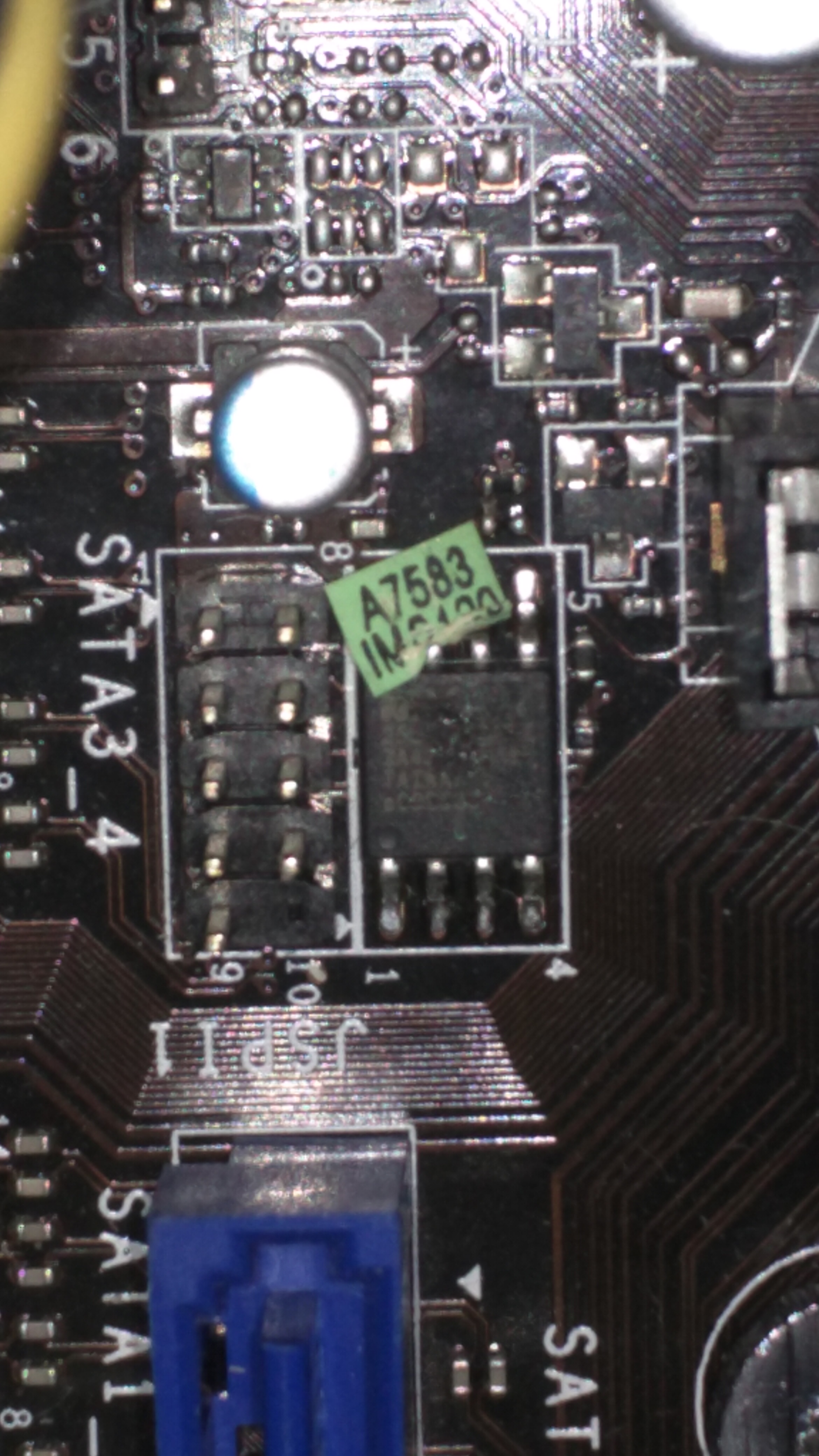
Thanks to your quick reply, the “name” of the BIOS CHIP on my motherboard is “A7583 IMS120”, I didn’t try search this on the compatibility list, I go check it now.
Checked but I din’t see it in the list too…
I’m not sure it’s my BIOS CHIP, but I see on internet someone say it’s this components…
I search for information about it but I didn’t found a lot of information on Google so I don’t know.
And Fernando, I’m sorry, it’s not a request, I wrote wrongly, I wanna say you thanks for your future message before you post 
English is not my main language so I do a lot of mistake like this, sorry 
Ahh, ok, is "A7583 IMS120" what is written on the IC itself? it sounds more like a MSI BIOS version.
Otherwise you need to look at the motherboard, and read what is written on the actual BIOS chip, it may be for example a Winbond chip, and there will be a model number, for example: W25Q128BV.
This is what needs to be known to see if it is supported by Flashrom, and to know if it is a 3.3V or 1.8V chip.
EDIT: If there is a sticker on top of the BIOS chip, you need to remove it, and see what is written on the chip itself.
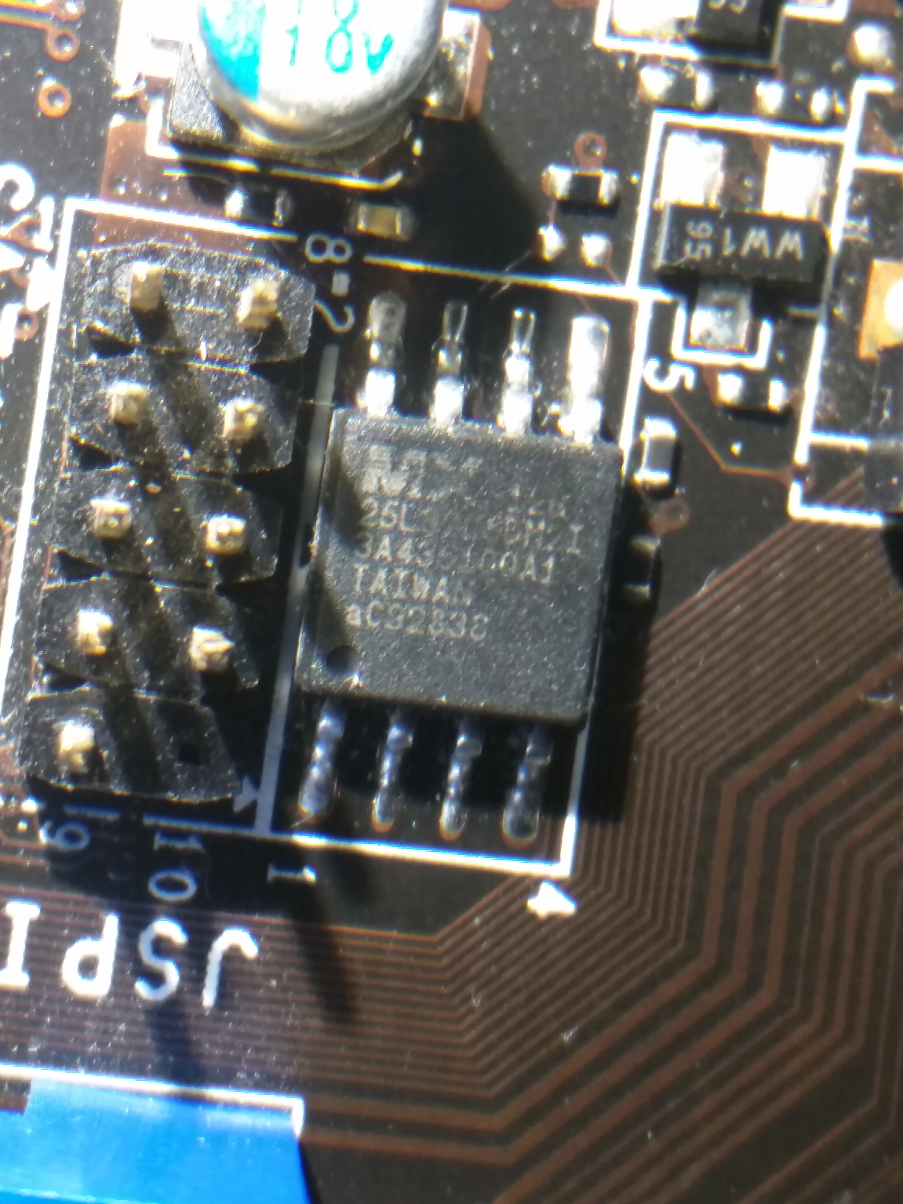
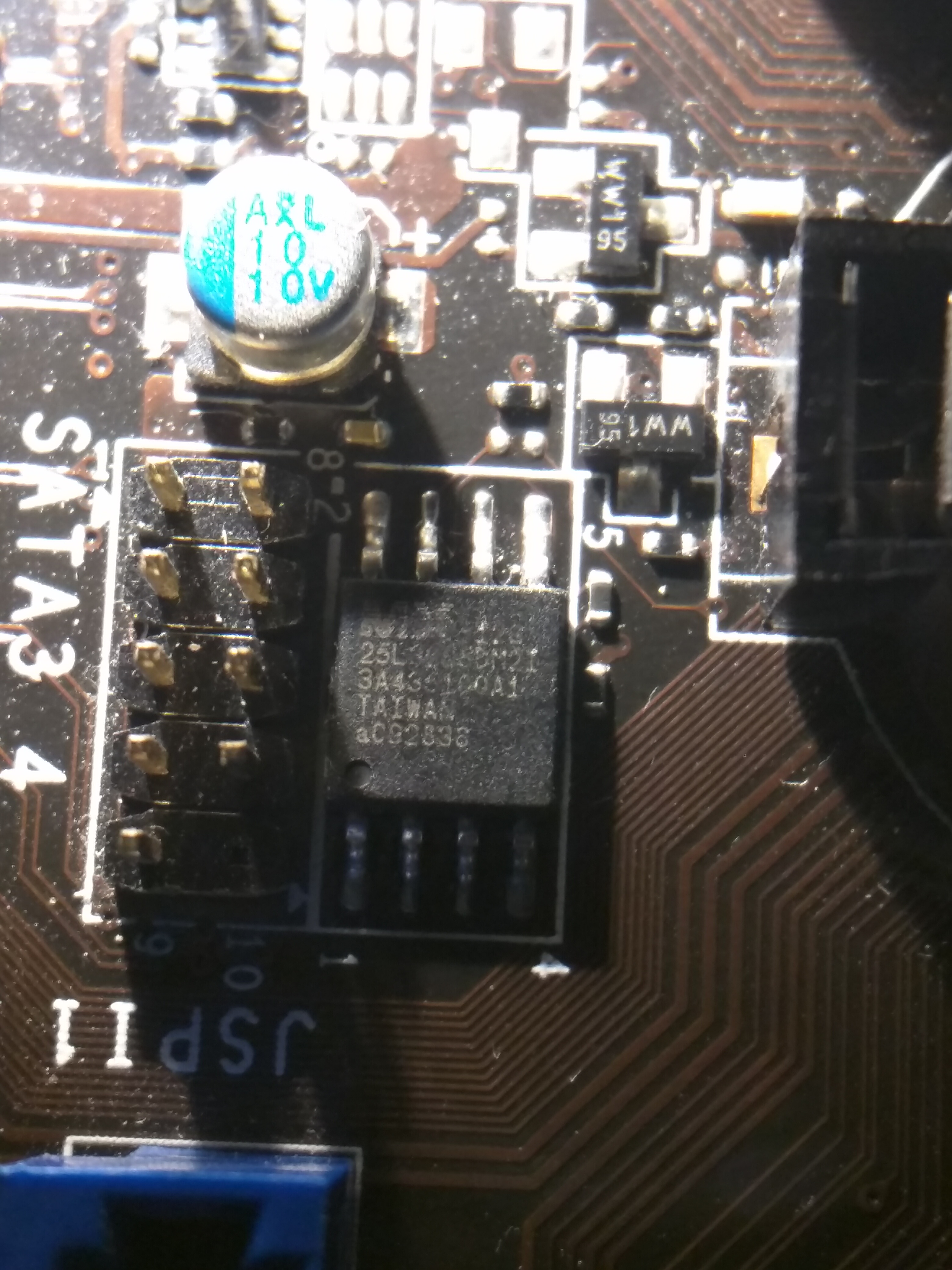
I remove the sticker, but that start to disappear, I give u some photo I taken, I cannot read this rrectly but me I see
MX 128
25L3ACSDM2I
3443S100A1
TAIWAN
aC92938
I’m not sure, I don’t have my glass…
Ok, it is a Macronix chip, i can not find anything on "25L3ACSDM2I" is it possible that it says something like 25L320 and some more numbers?, it was difficult to see on the Pictures.
There is for example 25L3205, 25L3206.
EDIT: I Think it might be a 25L3205DM2I.
the MX 128, would probably be MX-12G
Yeah you right, it’s a 25L3205DM2I, this can be flashed ?
I didn’t find this code in the compatibility list (I found 25L3205D only)
Yes, it can be flashed, the model is 25L3205D, the last characters are the type of packaging for example, SOP or DIP.
So, then the problem is that the chip is soldered to the board, some people, including myself, have been able to flash the chip, while it is still on the board, just remove the battery first.
But, it doesn’t Always work, in that case it can work if you desolder only the VCC pin from the board, and have it connected to the Raspberry.
For SOIC chips, it is very helpful with one of these, otherwise you would have to carefully solder some wires to the chip while it is still on the motherboard.
So I need this :
IC Test Clips EEPROM/ 93CXX / 25CXX / 24CXX Program SOIC 8 WAY
Raspberry PI
And some electrical cable
That’s all ?
I’m not very skilled with the use of electrical installation…
Sorry for the inconvenience, and thanks for your wonderful help 
Edit : I found that :
http://www.alldatasheet.com/datasheet-pd…MX25L3205D.html
But I didn’t see the type of the chip (voltage) and there is 4 pin configuration so I’m a little lost 
Yes, that should be all you need.
On page 4 in the datasheet, you can see that the chip is 3.3V (VCC) and the pinout, you have the "8-PIN SOP (200mil)"
But like i said, it may be necessary to desolder and lift one pin.
I have one last newbie question, how can I apply 3.3V to the chips ?
From Raspberry, ore I need a generator ?
You see I didn’t have a lot of money, I’m gonna buy the rasberry and the “eBay things” but if I need a generator too it’s gonna be painful for my money…
Yes, you get the 3.3V from the raspberry.
But, i assumed you had a Raspberry, if you don’t then this guide is a cheaper, and maybe simpler way.
Added some information to the guide about flashing MSI motherboards using the JSPI1 header.
Hi,
I want to flash my bios chip its an winbond w25q32b and my motherboard is an ASUS P8H67.
I have read that on ASUS Chips there are informations like MAC-Adress and others. Is it a big problem if I loose them?
thanks!
I’m trying to reflash the BIOS on an asus laptop s56ca-bh51-cb, with the BIOS chip WINBOND W25Q64BV datasheet here: http://pdf1.alldatasheet.com/datasheet-p…D/W25Q64BV.html
I have a few questions:
1: Same as above, will re-flashing it erase anything important?
2: I found the BIOS here, but how do I tell if it’s the right format / size? The motherboard is intel, but the link you provided about formatting for intel is dead. How do I re-format it to make sure it will work correctly?
http://dlcdnet.asus.com/pub/ASUS/nb/K56CA/K56CAAS208.zip
3: The value of the capacitor, does it have to be ~47 MicroFarad 3 volts? Will one rated 10 volts work? Or will it fry things?