If i am taking out the only bios chip the board has how am I going to use it with the programmer with the bios chip removed?
Would I need to order another bios chip?
You better have a laptop or a 2nd PC to use the CH341A with.
But yes, you can remove the Chip after Boot and overwrite it using the prgrammer and the started PC wihtout Bios-Chip! The Bios is only used at the beginning of the PC-Start Process. If the flashed Bios is non-functional, though, The PC won’t start anymore. Be sure to make a backup of your former Bios. You can order a Chip with that particular Bios afterwards or flash the backup-file with an other PC.
If you need a CH341A I still have one and can ship it from Germany.
I have a backup of the bios on my flashdrive that is connected to the pc right now
I forgot to mention that I ordered a programmer last night.
well done, but sry you did not take mine 
Hi all.
For those who search Bin file for laptop and desktop, you can go here FREELY :
http://www.laboneinside.com/category/laptop-bios/
http://1bios.ru/bios/notebook
Hope this 2 url can save your life !
I would not use those though… If anyone needs, I still have a CH341A Writer in Germany.
Are there any official sources to get drivers and software for these CH341A devices? Also, is there a consensus on which programmer is best?
I really don’t want to buy one of these, and have to experiment with various questionable Chinese programs/drivers.
Hello, I have not finded the sources of CH341A for Windows operative systems however you can download the 1.30 cracked official version of CH341A in the followings links:
https://cloud.mail.ru/public/2cQw/4uXMfb9pp
https://yadi.sk/d/c1–HVccsBi8E
For unsecurity or unlocked usb dongles of CH341 by the moment the latest official version is: 1.31 (for security or locked usb dongles of CH341A actually the latest version is: 1.33). I hope in comings months the cracked version 1.31 at least
@plutomaniac ,
I’m trying to flash a bricked MSI Z97 Gaming 5. The chip (MXIC MX 25L6473E) is soldered. As you had the same issue, I was wondering how you solved it. I have I think the same usb CH341A dongle and the same clip as you do. I tried the clip but I couldn’t get the chip to be recognized. Should I try to power the board? Desolder the chip?
Thanks in advance for your feedback.
@ abstract:
Personally I couldn’t get the chip to be recognized without power and with the laptop’s power it would just sort. So I payed someone to dissolder and resolder after I flashed the chip with a proper firmware with the FD unlocked so that I wouldn’t have to do something like that again (hopefully).
Ok Thank you. I guess I’ll have to do dissolder it too.
I just wonder what’s the use of the clip.
I flashed 16-pin chip with this programmer. No problems, chip was detected and flashed
Short Q:
Could be a problem if I’ve used CH341A v1.17 Programmer software that have in list only W25Q128BV instead of W25Q128FV the last one being my original Chip too?
According to the manuals (BV version page 71 Ordering information section and FV version page 97), 128B or 128F the same density 128M-bit, V=2.7…3.6V in both cases.
I don’t see any difference, more than that, I have successfully writen / verified the Bios chip and get into the windows again.
Any thoughts? thanks
How must I put the chip on?
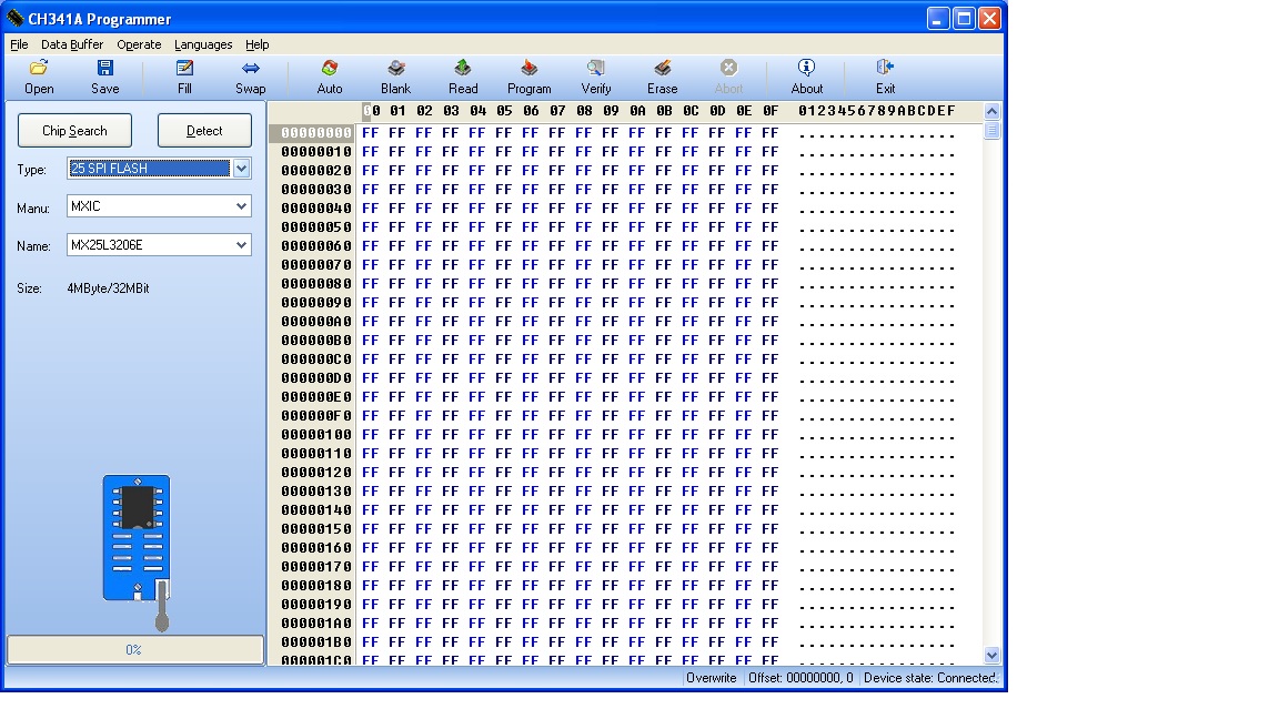
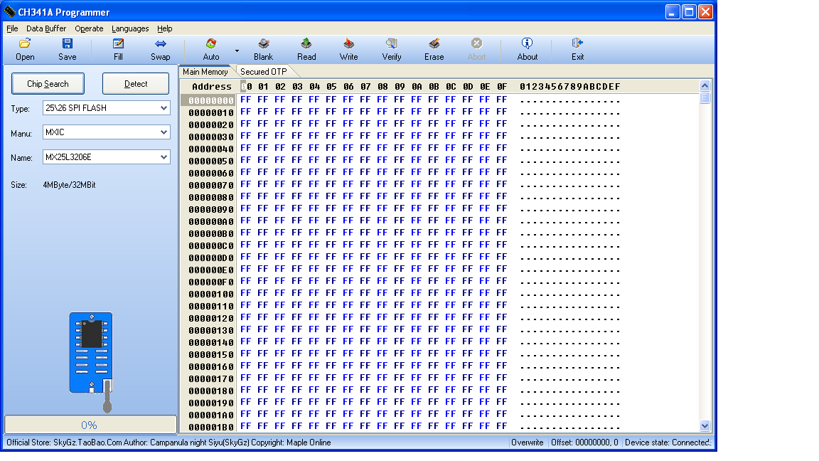
Depends on version, the chip is in different places.
This is version 1.18

And this is 1.29

Thanks
Hi there, any recommendations for 1.8V converters? Don’t need one right now, just want to have one for the future.
Thanks in advance!
I have one of these ch341 boards with just 16 pins http://www.chinalctech.com/index.php?_m=…=view&p_id=1220
I’ve just downloaded the 1.30 software
I think different versions of the software map to different pins?
Can anyone direct me to the mappings to figure out how to connect to eeprom chips?
The 16 pins on the board from the top are:
Vcc Vcc
GND SDA
CS0 SCL
CS1 GND
CS2 VCC
SCK TXD
MOSI RXD
MIS0 GND
So, I’m trying to connect to AT2402 with pin layout
A0 VCC
A1 WP
A2 SCL
GND SDA
I’m using a chip clamp with cable finished in 8 pin socket. It seems to me that it’s not just a case of plugging into any of the 8 pins - I need to map the pins?
VCC, GND, SCL & SDA are clear but where to map A0, A1, A2 & WP?
DoI need to connect A0, A1, A2 to CS0, CS1, CS2?
Do I need to connect WP?
This is assuming the software isn’t changing the pin names printed on the board (if that’s possible)
Use version 1.18
Version 1.30 indicates improper connection of the chip and not running correctly.
Sorry, I was editing my post when you posted - I really need the pin mappings for any downloadable version of the software - is there any such mapping available for any of the software?