I bought a device where the flash chip onboard happens to be an XM25QH128C by XMC from the now world-famous Wuhan. Since FlashROM support for this chip was only added recently, none of the existing Windows builds around come with it. So I built the latest current version for my own use. Sharing it below for the benefit of the community.
Works with the usual “driver” (really just an .inf file for VID:PID 1A86:5512), which is included in the ZIP as well. Credit for it goes to @flashrom I think, who also shared several builds here in the past. Might need to temporarily disable signature enforcement to install if you don’t already have it.
For driver installation issues, check the earlier posts in the thread: it’s been discussed extensively, and nothing’s changed since.
Only dependency is on libwinpthread-1.dll, which should be in the same directory. If you get an error: “The application was unable to start correctly (0xc000007b)”, it means this DLL file is missing.
Other libraries (libusb) are linked statically.
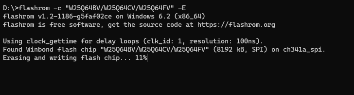
Output is verbose. Most warnings can be ignored unless there is an actual error. In particular: “Cannot detach the existing USB driver. Claiming the interface may fail.” is benign.
Note that the best practice is to connect directly to a USB port on the system board, not shared with any other devices, and especially not through any USB hub.
This build hasn’t been extensively tested, and since it’s just a snapshot cloned as-is from GitHub, it’s certainly not guaranteed to be stable. That being said, I tried reading and writing with a loose Winbond W25Q64FV I have lying around, and all worked fine (verifying too). For the record, I couldn’t check with an actual XM25QH128C as I don’t have the device yet. Still:
I won’t be responsible if you run into issues. If you don’t need support for any of the newer chips (see below), consider using any of the earlier builds already battle-proven in many scenarios.
Also included in the ZIP is the ich_descriptors_tool.exe tool, which builds together.
Updated Chip List
Over the version I was previously using (the one built and shared here by @flashrom), support has been added or expanded for over 60 chips:
I also couldn’t find any comprehensive and current build instructions for Windows, so here they are. To build, get MSys2 and run the following in the MSys2 MinGW64 shell:
After building, remember to copy libwinpthread-1.dll you can find in mingw64/bin directory together with flashrom.exe if you want to use this build of FlashROM outside the MSys2 MinGW64 shell, or on another device.
Note: it’s almost certainly not necessary to install the whole cc meta-package, just faster to grab it all rather than figure out which parts are needed (if you’re a lazy person with a fast connection at least). As a matter of fact, binutils might not be required either.
Enjoy!
PS Massive thanks to @flashrom for providing the earlier builds, which kept me going for years, without having to build it on my own.
Hello,
Sorry to bug. I’m in exactly the same situation as you were with this motherboard. Is there any chance you could share that Manufacturer file: 30528.BIN you got from them. They not answering me unfortunately. Will much appreciate your kind help.
Regards,
Does this programmer work with bios chip of asus b450m-a prime. I’m a newbie and I appreciate any help.
P.S. Does anybody know if there is a pin on Ryzen 2600 not making proper contact with the socket not saving date and time? CMOS is good btw. BIOS/UEFI Settings are being saved.
@Starfox
What’s wrong with the IC specs pdf from Winbond?
Isn’t this the most secure source of specifications regarding the IC correct operation and functions?
EDIT: Also latest CH341A back version, usually don’t need this fix anymore unless its old stock.
What more pins do you want with 3.3v…
“The device operates on a single 2.7V to 3.6V power supply”
And what’s that table…3.3 voltage on 7 pins???
You did what you did… so give it USB power and measure yourself the jumper cable output for VCC, this is where the IC need its input… what do you think that feeds the SPI_CMOS circuit???
How about when we have a motherboard with PSU_PW in standby or when remove/insert the CMOS battery… play a bit and do some measures for understanding.
Can you please say about Boya BY 25Q128AS flash chip how to read data from it using flashrom?
I am beginner in this field please enlighten me with your experience in this field.
Hello. It might be a dumb question but I have a winband 25Q64JVS1Q (Last Q could be a 0 idk) bios chip on a MSI H110M-VH PLUS. Can I flash that with a CH341A flasher?
The CH341A is a programming device, it works with a lot of flashing apps and ICs.
These apps must support the IC in their database, so primary it has nothing to do with the device itself.
Hello,
I think I did a mess with my motherboard, Prime X370-Pro.
It has the bios chip soldered and I want a 5900x to work while it had an old bios.
So I updated it with my Xgecu T48 and a clamp connected to the chip.
It took me various attempts to correctly connect it, but the Xgecu is very helpful in describing which pin needs better connection.
I successfully updated the bios, verify it multiple times.
The system won’t start.
Purchased a 3600 just to be sure it was not the cpu, same result….
Downgraded the bios to the first Ryzen 3000 compatible (4801), same result.
Now, is it possible that I bricked the chip, even if the Xgecu does not give me any error signal?
Maybe the flash method is not ok?
Maybe sone other chip needs to be flashed apart from the bios itself (happens with some ROG motherboards)?
Help is appreciated.
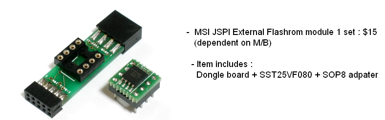
Plus, can someone point me to this very good adapter on EBay
The programmer is a T48 Xgecu, it supports basically everything. It is not a cheap ch341a.
That said, I am sure the little tool I am asking for can be of help.
I tried to do the connection myself but I was not successful, the pins are too close to each other.
I really need to find the tool.
Does it exist, cause you saw an MSI header connector? You’re the one that pointed… so where is it? Did you got any anwser from the “chinese” guys?
Or is it this only your own assumption… keep digging.
Not sure I understood.
I am just asking another source of the tool the Lost’n Bios linked.
The Chinese guy (he is Korean btw and sold me some Tualatin adapters in the past) does not list it anymore.
Sir… in which post of yours from last 7 days, did you mentioned or asked for any file/tool linked to the forum past user Lost_N_BIOS Guru (Retired) ???
I only see a request for a similar adapter for Asus like the one linked for MSI header…
Care to explain the post #774
Now regarding your flash attempts, verification is not done with the app/device… JFYI…
Desolder the IC and check it outside the PCB, if still fails it may be damaged.