Earlier I made a post (that is now deleted) in which I described the horrible experience I had using my Ponoma SOIC8 clip, my CH341A programmer and NeoProgrammer.
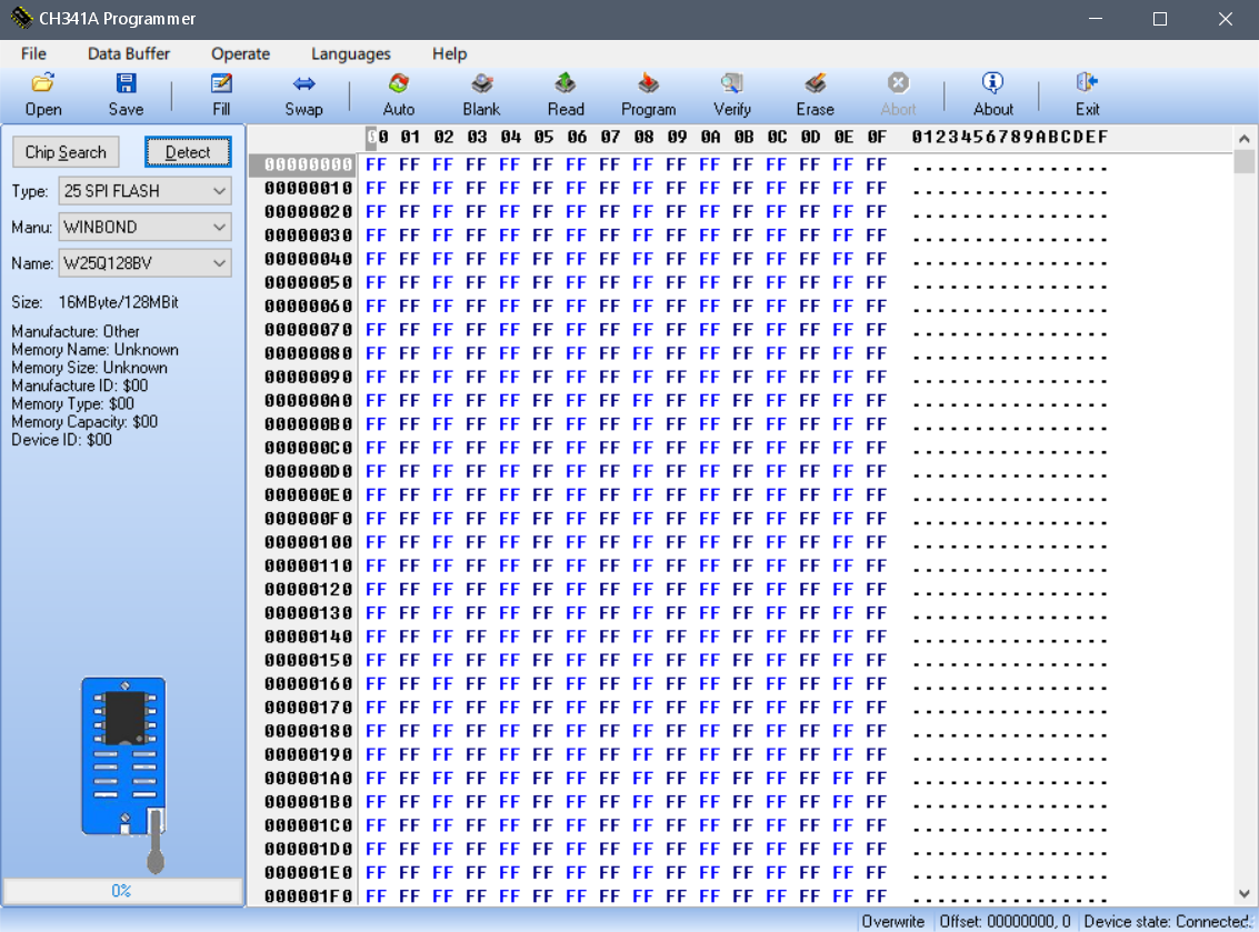
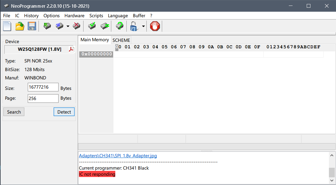
Basically, the device that I was flashing is a laptop with a Winbond chip, specifically the W25R128JWSQ, my CH341A programmer was set to 1.8V output so that was already good to go, but then NeoProgrammer would detect the chip as a W25Q128FW (ID was “EF6018”), but since there were two variants of that chip, it would give me the option to choose:
The W25Q128FW that’s at the top could read successfully, I got a good dump with it (and I know because I flashed it later but we’ll get to that part), but this exact “device configuration” could not write correctly, it would write, yeah, but it wouldn’t write what it was supposed to, so verification would fail and then I bricked the laptop, it wasn’t booting at all.
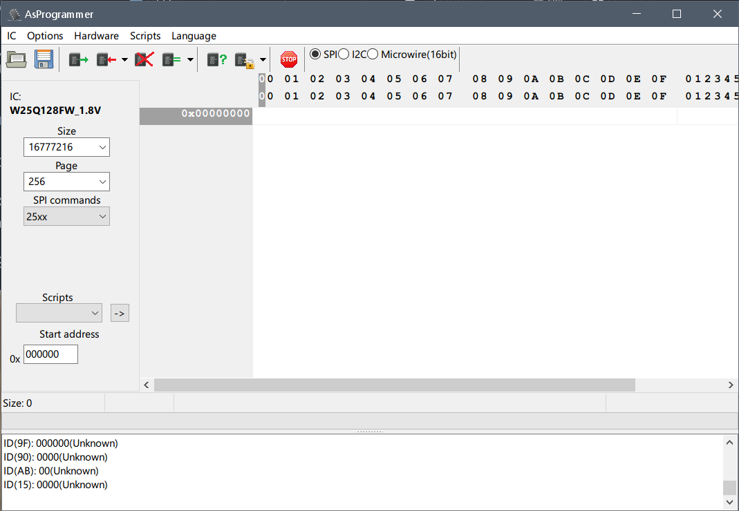
Then I turned to the other “device configuration”, the W25Q128FW_1.8V, which oddly enough in the “Volts” part says 3.3V but the name has 1.8V, however this one could do both read and write without any problems, which is kind of surprising and confusing at the same time, using this one I managed to flash the dump I got previously and the laptop booted without any problems, as expected it complained about the CMOS checksum (triggering a CMOS reset) but oddly enough none of my BIOS settings were reset.
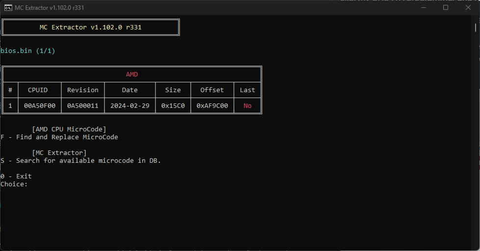
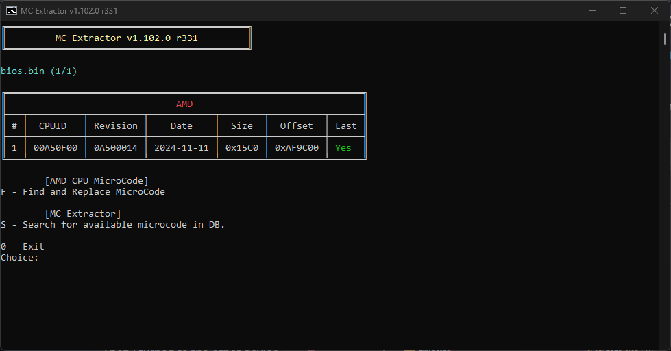
The BIOS that I wanted to flash was the same as the dump except that it had a higher microcode revision (to update it), it was modded using the latest version of UBU to include the higher microcode revision.
Original:
Modded:
If anyone wants the images:
So to summarize, the confusing mess that NeoProgrammer had with how it would detect my laptop’s SPI flash led me to brick the laptop, then I chose the correct SPI flash chip even though they should be the same and the correct one had a good flash on the first try.
No idea if the modded BIOS (based on the dump I made) is actually good or not and I don’t have time to test it out for now either, but at least my laptop is back.