You know your motherboard has a standard JSPI header that you could manually hookup to any programmer. Even better AliExpress sells a JSPI hookup cable thats made for the CH341A.
https://www.aliexpress.com/item/JSPI1-bu…sAbTest=ae803_4
Most MSI motherboards come with either an 11 pin or 9 pin header and your Z77 board has a 9 pin compatible with that cable adapter. Even though I own one myself never tried it out. However as long as you have connected your test clip to the dot on your bios chip matchin red wire to pin 1 and that dot it should work. Make sure pin 1 matched up correctly on your programmer.
From there make sure the test clips teeth are properly connected. If you have done that right the software should identify the chip if not try try again. Anyhow I prefer to use pitch wire and manually do the connection. That way I know I have solid connection. Just don’t give up. Keep trying.
@arenyx - Access violation error can be ignored. Use 1.30 software and W25Q64BV ID for W25Q64FV chips - due to this, be sure to make a new backup before you erase, blank check, write/verify (in case your previous backup is empty file FF/00)
http://s000.tinyupload.com/index.php?fil…257455007472602
@arenyx I also have the same error messages with CH341a programmer. I ended up using AsProgrammer 1.40 without any issues.
Certain BIOS chips need certain software, or different ID’s used etc, and yes, some will only work with ASProgrammer - W25Q64FV is not one that has to use ASProgrammer, but it will work fine there too.
I’m eager to give the jspi header you’re talking about. it’s right next to the bios chip right? marked jspi1?
I’m bummed it seems the clip has worn out and won’t hold a grip anymore. it’ll just slip out immediately so I’m not relying on that for now. Thanks for your help again guys this would be an even bigger headache if I was just ramming my head into it without any help.
Question: Can I wire the wires directly onto the chip? making sure every wire is accurate of course. I’m assuming the wires that come from the clip would work even without the clip.
Edit: If not , can I wire into the jspi1 ? ordering the actual cable is gonna take 2 months >.> If i can wangjangle a fix i’d be satisfied.
Yes thats the one. The one marked JSPI1. Should have 9 pins. I had similar issues with a test clip trying to backup a bios off of a Dell XPS 13 motherboard. Think it was the same bios chip as yours. Kept on slipping off. Took like 50 tries to get a solid connection while using downward force to keep it from coming off. Had to shave the plastic tip of the clip to get it to hold. Then ended up buying a couple extra clips off of Amazon last week. This one got good reviews:
https://www.amazon.com/CPT-063-Test-Clip…gateway&sr=8-15
Also buy these:
https://www.amazon.com/gp/product/B01EV7…0?ie=UTF8&psc=1
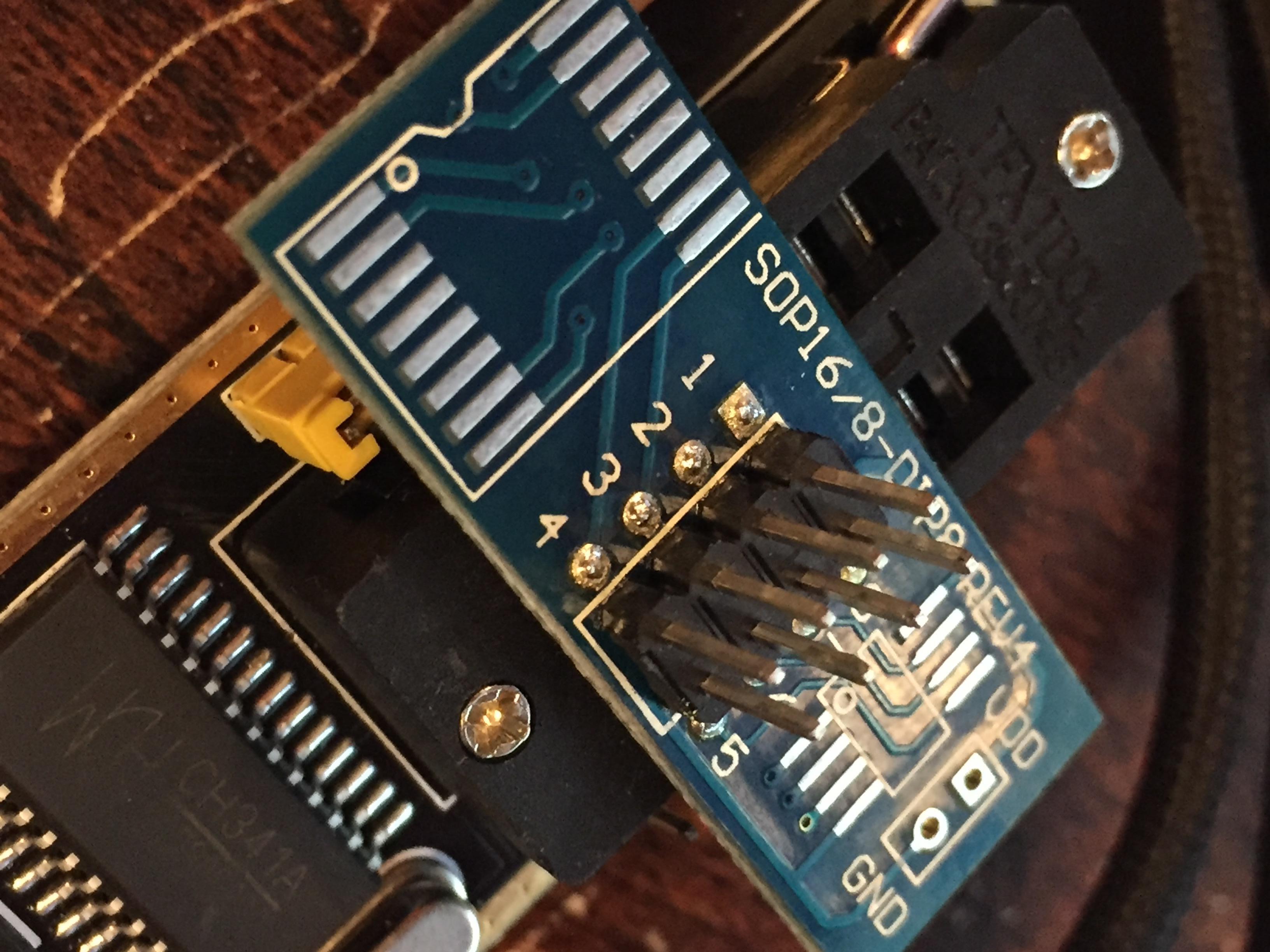
Also found this image that shows what those jumper pins on the side of the CH341A are for and with those pitch wires should be able to use the CH341A directly wired to the chip or the 9 pin header:
I see they have female to female. would i be able to connect those to this for a secure connection? avoiding the clip completely? THey look like they’d go into the jspi1 connection on the mobo. or am I just imagining?
[File:IMG_0687.JPG|none|auto]]

Well you wouldnt even need to use that blue test clip adapter. Should be able to use the side pins on the ch341a as depicted in that image I posted. Just connect CS to CS, CLK to CLK, SI to SO, SO to SI, GND to GND and so on.
Gotcha. I just ordered the cables and I’m gonna give it a try through the jspi1 spot on the mobo. Wish me luck fellas. We’re fixing this mobo if it’s the last thing we do lol
Connecting to the MSI JSPI header is a tricky process. According to this thread where someone was able to do a successful flash you have to jump pin 1 and pin 9 (Vcc and #Hold) together for this to work:
https://forum-en.msi.com/index.php?topic=256035.0
I saw, I should be able to jump those wires with just another piece of the same connectors right? Sacrificing one of the many they’re sending me for the greater good.
I suppose so. I would try baring a stretch on two wires and twist them together. Going to be some trial n error probably.
JSPI/JSPI1 header is really made to boot to a BIOS chip connected to that header, on a PCB or connected to a wired adapter, but yes it can be used to program too with some hassles.
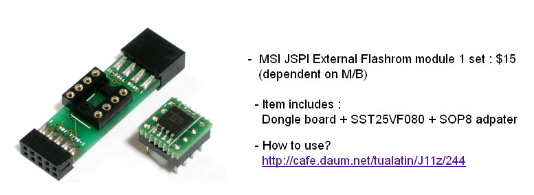
Here is PCB Type one I use, this has header for Asus on one side and MSI on the other, you’ll have to message seller and tell him you want to purchase that item only since he doesn’t have listing for this only
Or purchase the programmer and before paying tell him you also want one of these adapters too. He’s fast to reply usually, and ships quick too, only two weeks to arrive every time I’ve ordered from him (5-6+ times)
https://www.ebay.com/itm/270838478198
Scroll down towards end of listing, you will see the item I’m talking about, comes with chip and you can request certain one or certain size too if you want - MSI JSPI External Flashrom module 1 set : $15

Or there is also this, more homemade solution, like you are doing but made to last a bit longer and has header adapter too
https://www.ebay.com/itm/232939491701
@arenyx - for your slipping issue, you can try to pull the little fingers back out a little bit inside the clip, or scratch them up a little so they have some grip too.
Also, adding a semi-tight rubber band around the tip could help grip too, be careful though you can break the BIOS legs if you squeeze them too hard.
ill Look into trying to fix the clip with your suggestions. If I can’t get this solution to work with just cables then I’ll reevaluate my options. That module does look interesting and might be worth the wait but I’ll honestly probably invest In a new mobo before I try anything further after this next attempt and try fixing this mobo as a fun side project. Unfortunately I need a working mobo sooner than later.
I know what you mean, luckily I’ve amassed all these kind of BIOS tools in advance, due to fixing boards to reseller, so I always have them before I need them anyway.
On the clips, sometimes the metal gets pushed too far back into the plastic, pulling forward some can help sometimes if you can get them to move. You’ll be able to see if one or more is pushed too far back.
quick question, there’s a VCC connection that I can’t find on the ch341a programmer?
Edit: That goes from my chip to the 3v3 connector on the programmer?
Its on post #326 and its the pin labeled 3V3.
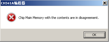
Well I got it all hooked up and it detected the chip. It erased and blanked but when I try to write it gives me this error at 100%
Edit: forgot the image

Use another version or AsProgrammer. This is why I no longer use a ch341a.
Also sure you wired SO to SI and SI to SO correctly?