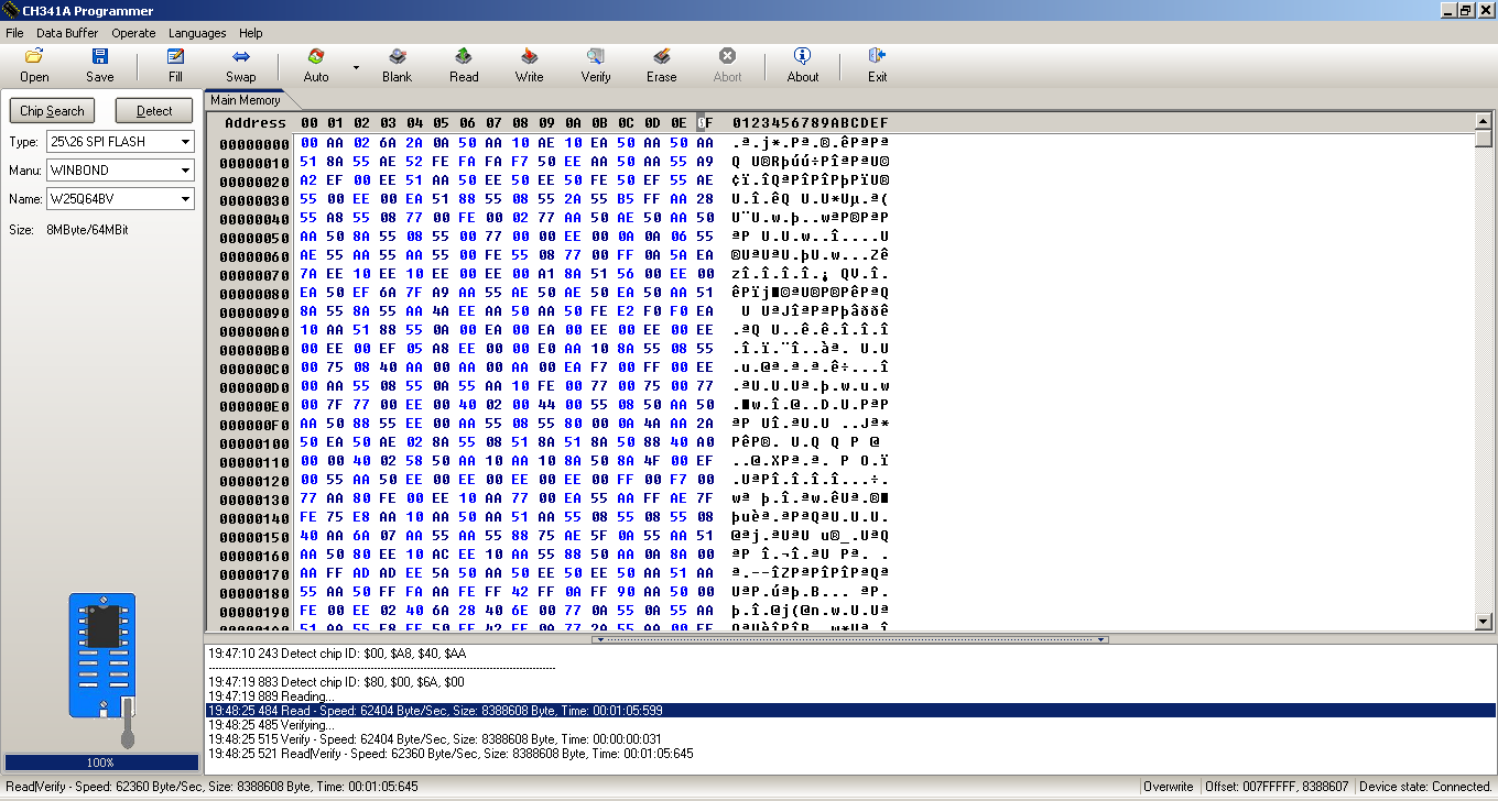
good news! I managed to get to the success partwhere it says chip and buffer are the same after flashing. sadly the pc is still stuck in this odd loop. Guess im still screwed?
Can you dump the bios off of the chip to confirm a successful flash?
do I just read and post the stuff in main memory?
I think so. Usually selecting read creates a dump of the rom chip.
not sure how to create dump file but here’s some of it from a screenshot. Where would it save the dump file?
Edit: Ill just link imgur since this is making it tiny. https://imgur.com/a/dDY6nWy

Usually it names it for you and saves it in the work folder. Got a higher res photo?
Open program, Read, then verify, then “Save”
Some MSI boards you cannot program BIOS through JSPI/JSPI1 - this is for BIOS recovery, you put a BIOS on USB stick, then boot to the BIOS on chip/PCB or on cable via JSPI, then enter BIOS and remove cable, then reflash BIOS on the board from MFlash while in BIOS.
So you may not be writing to the chip, compare your before and after dumps via hex, as well as compare current dump and BIOS you wanted to write.
And yes, you may need to use ASProgrammer 1.40, but I’ve never had any issues with W25Q64FV when using 1.30 and BV
It usually only shoes me FFFFF for everyithing. Only once did it show anything different now it’s just back to Fs. I wish I could go through that jspi1 method but I can’t even get to the bios when booting.
Thats why I recommend the Flashcat over the ch341a. Its like 4X more expensive but worth it.
See my thoughts and testing here with the adapter I mentioned, since I’ve only ever seen JSPI used as a BIOS source not program-through, even MSI flashcat videos show this (First video link below, similar pinouts as below shown at 1:27 in flashcat video).
I tested it vs the JPSI pins and made some diagrams, the user also made some and made his own cable adapter and a spare BIOS to boot from and he made an additional diagram of JSPI to spare BIOS
Flashing BIOS chip (MX25L3205D) with CH341A progammer - can’t detect chip
Maybe these also help
https://www.techpowerup.com/forums/threa…d.238973/page-8
https://www.techpowerup.com/forums/threa…-8#post-3767632
https://forum-en.msi.com/index.php?topic=256035.0
https://www.youtube.com/watch?v=UDSQCCuXXFk
https://www.youtube.com/watch?v=nFqFrf785xw
Hi all, I have problem with IC M45PE16. The ch341a programmer (black edition) cannot detect chip (only support 25xx). Anyone know this or any solution for me?
Thanks so much!
Hello huyho,
try AsProgrammer 1.40 and you’ll find the chip (Micron) here -> [IC] -> SPI -> NUMONYX -> M45PE16.
Best regards, MiMo
Thank you for this! I can confirm it’s fully working, and it’s a big improvement over the previous version.
Incidentally, 1.1 has just been released.
Does anyone have this file mirrored?
It seems like Wootever put all his eggs into one basket and all his efforts have gone to waste.
I recommend using the latest version by @flashrom from #214 linked above but if anyone needs it I am attaching a single ZIP with all the 3 versions that were posted in this thread so far: p1.0-109-g3bcd922 (newest), 0.9.9-97-g29333a0 (previous), and v0.9.9-r1954 (oldest).
Works for me (I just disable signature enforcement, did not test the batch script that temporarily installs a certificate, although it seems like a neat idea).
Flashrom 3 Versions.zip (487 KB)
Hi MM, first very thanks for your support. But when I do as your guide, Read ID excute like that(it mean programmer not detect my IC?). What is the problem? And 1 more question, why Read ID all FF? Although my IC is passed one.
Thank you.
Hi,
“FF” means, that no data or ID could be read from the chip.
Here no problem with Winbond chip:
I use black CH341a (USB\VID_1A86&PID_5512) and WinChipHead driver v2.1/2.2.2009.6 on Win7 64bit.
What programmer do you use & which driver?
In which direction is the chip plugged in (maybe screenshot)?
The point of the chip has to be left, directed to the 24xx port.
The chip themself should be plugged into the 8 contacts of 25xx port right (near to the usb-connector).
Like this way (red):
Be aware of using 3.3V and every pin is in it’s own port.
If the chip is going hot, unplugg the usb programmer.
Regards
Here is image guide to make sure you are connecting it all properly
[GUIDE] Flash BIOS with CH341A programmer
https://www.bios-mods.com/forum/Thread-G…341A-programmer << Same as one directly above, but with all images expanded/visible at once
Hi MiesMosel and Lost_N_BIOS,
After doing as your guide, I have realise that the issue come from wrong port. I already adjust and programmer well done now.
Thanks so much both of you for supporting me !
Hi folks,
I ordered today a SPI programmer : CH341A 24 25 Series EEPROM Flash BIOS USB Programmer
Do I need to do this fix before using it : Power supply fix
I will use it on a Winbond Serial NOR Flash - Product number : W25X05CLSNIG - Top side marking : 25X05CLNIG - Density : 512Kb - Vcc : 2.3V - 3.6V - ROG Asus G703VI laptop
Does someone has experience with this chip and wich program is best ? (I checked and only ASProgrammer has the chip values in database)
If someone know the way to mod the bios and flash it with the spi programmer. (Dump SPI programmer - edit dump with AMIBCP - Flash with SPI programmer ?)
Thanx in advance
@Svan
I was worried about that too so I took out my volt meter and checked the voltages which were all correct at 3.3 volts like they were suppose to be. At no time did I notice any irregular volts being put out. If your worried I suggest you do the same but you should be ok.
@Svan
Same here. No problem. Voltage is 3.3V on black CH341a programmer.
Best regards, MiMo