Hello,
i am selling a CH341A programmer in Black Edition with 1.8V-Adapter! Fresh buyed and new!
If you are interested in buying this device, you should contact me!
Regards…
My location is germany…
@ricktendo Tried to install on both Subsystem on Windows and separate laptop with Debian 8.
I installed Flashrom but i have problems installing the driver for ch341.
I reach a point where i try to “make” file and get error " recipe for target ‘default’ failed"
Edit:
make -C /lib/modules/4.4.0-43-Microsoft/build M=/home/username/CH341SER_LINUX
make[1]: *** /lib/modules/4/4/0-43-Microsoft/build: No such file or directory. STOP.
Makefile:5: recipe for target ‘default’ failed
make: *** [default] Error 2
HI
I had similar problems with CH341A and 25Q128FV. In which the official windows software related to the programmer was reading the chip successfully and erasing the chip also successfully but was not writing to the chip completely. and I was always receiving an error at the end of the verification process… I got an advice from a friend to try programming it via Linux using flashrom software. and while I was busy with find how to use Linux commands to install and use the programmer, I found a post online offering to use flashrom software in windows platform. and providing a simple driver for windows to recognise the programmer. Surprisingly, it worked with no problem and it is very easy to use. So, I am attaching the software for you to try it.
1- please extract the zip file to a folder then
2- right click on install.cmd and choose run as administrator (a command prompt windows will popup)
3- attach the CH341A programmer to the usb.
4- in the command prompt window, type flashrom then enter
5- type flashrom -r mybios.bin then enter ( this is to read the chip bios…please note that you can choose any name instead of mybios.bin,this is just to refer to the file name you want to save the read bios to… which will be your chip backup)
please make sure to do this step before using the following command
6- type flashrom -w bios.bin the press enter ( this is to write the file bios.bin to your chip, so please download and use the correct bios file here to write it to your chip. again, note that I refered to the bios file by the name bios.bin. but you can use your downloaded file name or you can rename the downloaded bios file name to bios.bin and apply exactly the mentioned command.
now, the program will read, erase the old chip, then it will write the the new bios to the chip and verify it.
you can use flashrom -r newdump.bin to read the bios chip again to a new backup file I called it here newdump.bin
then you can compare the bios file that you downloaded and the one you just programmed, to see if they are identical. so you will make sure that the chip has exactly the same bios file that you send it to the chip.
note that you don’t need to install any drivers. just run install.cmd as administrator …
the commands are similar ones in Linux.
hope this help to avoid CH341a software errors
flashrom_windows.rar (161 KB)
Thank for response but…
@Wootever posted couple of pages above, flashrom-windows version 0.9.9 which i’ve been using and it’s working good so far.
I managed to revive 10 boards already by cloning the original firmware.
The thing is, it takes like 1 hour to copy the new firmware on a new chip using this cheap CH341A programmer. I’ve seen in the logs of flashrom 1.0, that they added an option to go straight to erase/write and then verify, without reading first.
This could save me 10-20 min on each board, and i have a lot to fix.
@weelcup your version is the same as @wootever posted earlier, and i thank you both for responding to this thread.
I would really benefit for the version 1.0 atleast in theory. Thats why i’m trying to make it work.
Best Regards
Oh sorry I didn’t go through all posts. I was search through Google and got to the post. And I wanted to help as I was facing almost a similar issue.
Yes I think ver 1.0 would be great. Keep going.
And u apologies to @Wootever as I didnt go through his post before I posted.
Thanks
Do you have a problem with ubuntu and ch341prog that "erase time out" every time?
Okey, windows version is working just fine. I thought that linux version is more reliable. ![]()
Thank you @Wootever , this is much appreciated. I was just trying to reflash a GD25Q64, which SkyGz’s tool could only read but not write to, and your flashrom handled the job perfectly.
For the record, erasing (-E) still failed for me but it’s just a minor detail, as -w can be used directly.
Hi, this is my first post, so if i’m doing something wrong, sorry from the beginning.
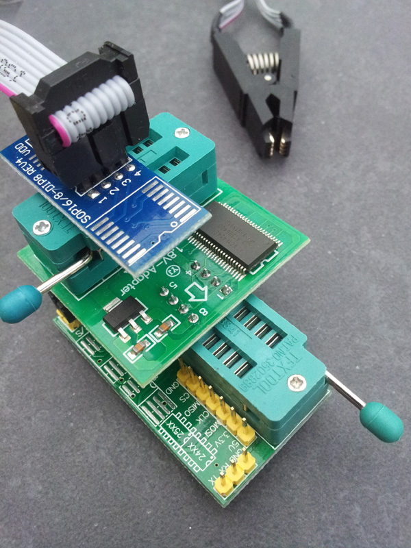
i finally could flash the rom to the Macronix MX25U12873F chip (relatively new chip),with the SkyGz’s software ch341A programmer v1.31(not quite true, i’m going to explain in a moment). MX25U12873F chip is 1.8V, 16MB/128MBit , from Asrock Fatality AB350 gaming itx motherboard for ryzen processor.
Actually v1.31 is paid version but also which happen to came with free program also(namely CH341AFree v1.4) in the package that has less userfriendly properties; just have choices -24EEPROM, -25SPI/FLASH and -chip size/speed( like 1MB/8MBit to 16MB/128MBit).
i used virtual WinXP working on vmware, CH341A MinProgrammer hardware(aliexpress product , “CH341A Programment” and " CH341A Pro" writes on blackpcb), 1.8v adapter(green pcb, from also aliexpress ) and soc8 test clip(thak you aliexpress : ) ) to hold the chip easily.
The SkyGz’s “Ch341 Programmer” v1.29 and v1.30 didn’t write properly i presume, because couldn’t verify(exit in half with error) the chip which was written by itself.
In v1.31 free version, just selected “25 SPI FLASH” and “16MB/128MBit” choices, can erase the chip and writes the rom perfectly, then verified. Also could read the rom in chip which completely same with the original rom.
P.S. My bios chip has a housing socket on motherboard, so i could remove from motherboard easily(just opened the hosuing doors and removed it). So i didn’t do the flashing on motherboard.
Hi, this is my first post ![]()
I have a 5950g Acer motherboard with a dead InsydeH20 BIOS (wrong versions flashed). The known Acer “Fn ECS” sequence does not work, so I intended to flash the BIOS.
I bought a CH341A programmer with a SOP clip, which did not work a the beginning (chip not recognized). I then found the schematic diagram of the motherboard in the internet (which is actually a Compal_LA-6931P). In order to flash the chip an SMD bridge needs to open (normally short), so I have unsoldered it. I can now read the chip, which is a MX25L3206E, I can erase it, blank check, but any trial to burn it brings a “don’t match” error. Portions of the chip are not being written correctly, but the location and number of wrongly burnt cells vary.
I have used various versions of the software (1.13, 1.18) under Windows 10 64bit, but no success (always similar behavior - correct recognition, erase, blank check, burn - error).
Does anybody know this particular motherboard and/or have similar problems and could help me please?
As alternative I have already ordered blank (empty) chips, intend to burn them and then re-solder the BIOS, but I would be glad to avoid it.
Thank your in advance!
In the meantime I have found out that my "black" CH341A Programmer is a "false design" model, i.e. has 5V active signals (MOSI and CLK), instead of 3.3V. Following information found on Internet I have rewired the programmer to 3.3V and tried again to program the MX25L3206E chip without unsoldering it. This time the programmer DOES NOT even recognise the chip.
1. Either there is a power supply issue reported elsewhere, when programming the chip onboard (without usoldering it), where the programmer needs to "power" the entire maniboard, or
2. The chip is alread down
Some people warn against using the "unmodified" programmer (i.e. with 5V signals), as this may fry the 3.3V chip - is this my case? Other report no problems with programming 3.3V chips with the 5V (deafult) version of the programmer.
I will now come back to the "5V" version and see what happens.
I suspect 5V without load may become something much closer to 3.3V if enough load is applied…
In the "5V" mode the same behavior as before - the chip is being recognised, can be erased and blank-checked, but no programming is possible. I assume the chip cannot be burnt on-board and needs to be desoldered.
I have ordered a preprogrammed BIOS for this particular board and a couple of blank chips. I will then try to read the preprogrammed BIOS (in "3.3V" mode, to be on the safe side) and see if I can clone it with this programmer. I will then desolder the BIOS from the board and check if it can still be programmed. If yes - it would confirm my suspection (onboard flashing not possible, probably power problem) and I will fit the board with a new BIOS.
In the circuit diagram of the motherboard I have found a mysterious notice concering on-board flashing, which I cannot follow anywhere else, so perhpas something more needs to be done in order to burn an on-board BIOS.
Hi, thanks for your info about the new MX25U12873F, I need to flash one on a MSI PC MATE…
I use a CH341A (the green one) which connected and works, but when I plug the 1.8V adaptor on it, it disconnected !
also the red light on the CH341A still light on but little less strong…
I use for now the SkyGz’s “Ch341 Programmer” v1.30 waiting that my hardware (CH341A + 1.8V Adaptor) are connected before to buy the last version 1.34
Could You please see my picture and confirm that my setting works on ?
Do you think is the 1.8V Adaptor that doesn’t work ?
I bought them throw Aliexpress…
Your ch341a part(green pcb) is different from mine, but your configuration seems right to me(i have a photo of my config), but cannot be %100 sure because of it’s different pcb.
if disconnected from pc when 1.8v adapter just plugged to ch341a, it can be a problem from 1.8v adapter.
you don’t have to buy 1.34 version, free CH341AFree v1.4 version(in 1.31 package) is doing the job just fine.
Hi, I want to offer an alternative software for ch341a. I successfully used it for w25q128fvssig and gd25b128cpig. I hope someone will be useful
AsProgrammer_1.4.0.zip
Hi again,
to complete the status (should the topic be of interest to anybody):
1. The BIOS chip (MX25L3206E) of the 5950g Acer laptop motherboard cannot be flashed with the CH341A + clip without being removed from the board. The comment found in the board documentation (circuit diagram / schematics) is unclear - the power supply needs definitely to be detached from the chip, but there are no jumpers on the board to do so. A tiny smd component can unsoldered, but flashing is still not possible. Several trials to on-board flash the chip with the above programmer/clip did not succeed. However, atfer unsoldering it from the board the chip was recognised and could be flashed (in an appropriate socket) without any problem.
Conslusion: the 5950g BIOS cannot be (easily?) reflahsed on-board and needs to be unsoldered.
2. My CH341A programmer ("black" edition) has a design bug: two signals are powered with 5V, even if the chip to be flashed is a 3.3V one. Simple rewiring of the programmer makes it a 3.3V compatible (the change is permament, no 3.3V - 5V jumper switching). However, the 5V did not damage the BIOS chip, which could be reflashed after unsoldering from the board.
Conclusion: the 5V "bug" in the pogrammer circuitry does not seem to harm the MX25L3206E chip (and possibly other as well).
Regards
Unimag18
Hello all, first time poster. I just wanted to say thanks for the thread. This info helped me out while recovering from a bad EUFI flash.
I got the “Black edition” type programmer similar to the first link in the 8th post in this thread by plutomaniac and used it to flash the EUFI EEprom that came with my ASRock Extreme6 Z77 board.
At first I had numerous failed attempts to detect the chip when placed in the programmer but finally after many trys it finally worked. I didn’t do anything differently; maybe that last time I was more electrically grounded when I seated the chip in the programmer? I have no idea what made the difference but linux flashrom utility finally detected it.
The chip was a Winbond W25Q64BVAIG and flashrom detected it as W25Q64.V . The chip was very finicky and only showed up finally after many tries. But at which point I was able to read from it and then write to it (flashrom automatically read then erased then wrote using only the write command).
After which everything worked fine, I was able to boot up again and all my motherboard specific info such as MAC address seems to be intact. This thread helped me out immensely, thanks again!
I don’t know why, but the drivers included in flashrom archive by Wootever wont works anymore (I can’t install them).
Windows 7 x64, green & black CH341a. It worked fine 6 months ago…
I was able to use the program (with included drivers) linked in Nastojka’s post.
AsProgrammer works, but flashrom was handy with the autodetection feature, and it was also faster…
@Wootever : could you help me find out why your flashrom driver won’t install anymore ? What am I missing here ?