[HELP] MD70-Datto (Gigabyte MD70-HB0) BMC issues

Hello fellow members.

I am having some issues regaining complete functionality of BMC (MergePoint Embedded Management Software) on the Datto motherboard after flashing BMC.

I am trying to repurpose our datto backup appliance which is in essence a 24-bay 4U server with the following configuration:

SuperMicro Chassis 846BE1C-R1K28B
https://www.supermicro.com/en/products/c…C846BE1C-R1K28B

MD70-DATTO Motherboard (identical to Gigabyte MD70-HB0)
https://www.gigabyte.com/ca/Enterprise/S…MD70-HB0-rev-12
Manual:
https://download.gigabyte.com/FileList/M…0hbx_e_1202.pdf

Despite a few online reports of unsuccessful BIOS flashing using original BIOS firmware from Gigabyte (onboard NICs end up losing their MAC addresses) I was able to flash the BIOS without any problems.

In case someone finds this helpful: I’ve booted into the Windows x64 Live CD (in my case Active@ Boot Disk but any Windows based Live CD tools should do) and launched

1
 
AFUWINx64.EXE image.bin /P /B /N /X /K /L /ME
 

then once flashing was successful, shut down, unplugged power for 1 minute, plugged everything back in.


The next step was flashing the BMC. The latest official firmware version for AST2400 at the time of writing is 8.88/4.88.

This is the part where all the confusion started, leading to some issues.

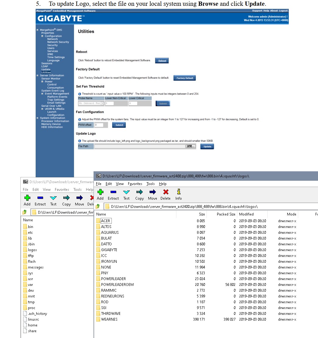
(1) When logged into BMC/MergePoint EMS, first thing I noticed was the proprietary banner from Datto as opposed to Gigabyte:

Datto.PNG


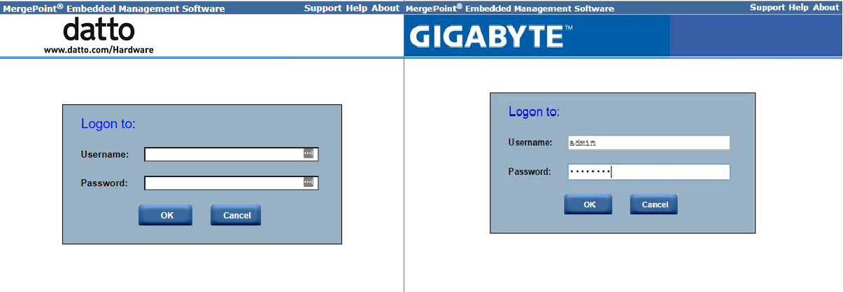
After updating the firmware to v8.88 from Gigabyte (more on this later) the datto banner remains in place. I ran the update a few times by logging into BMC/MergePoint EMS > update > upload BMC firmware image, and I tried both options - to preserve user data and not to. No difference. Even the user list remains the same, but the version changes to 8.88.
Can anyone explain where this banner is stored if it’s persisting even after the BMC firmware update? How can I change it to the default one? Is it possible that unchecking [ ] preserve user settings is not applying for some reason, or there is another trick?

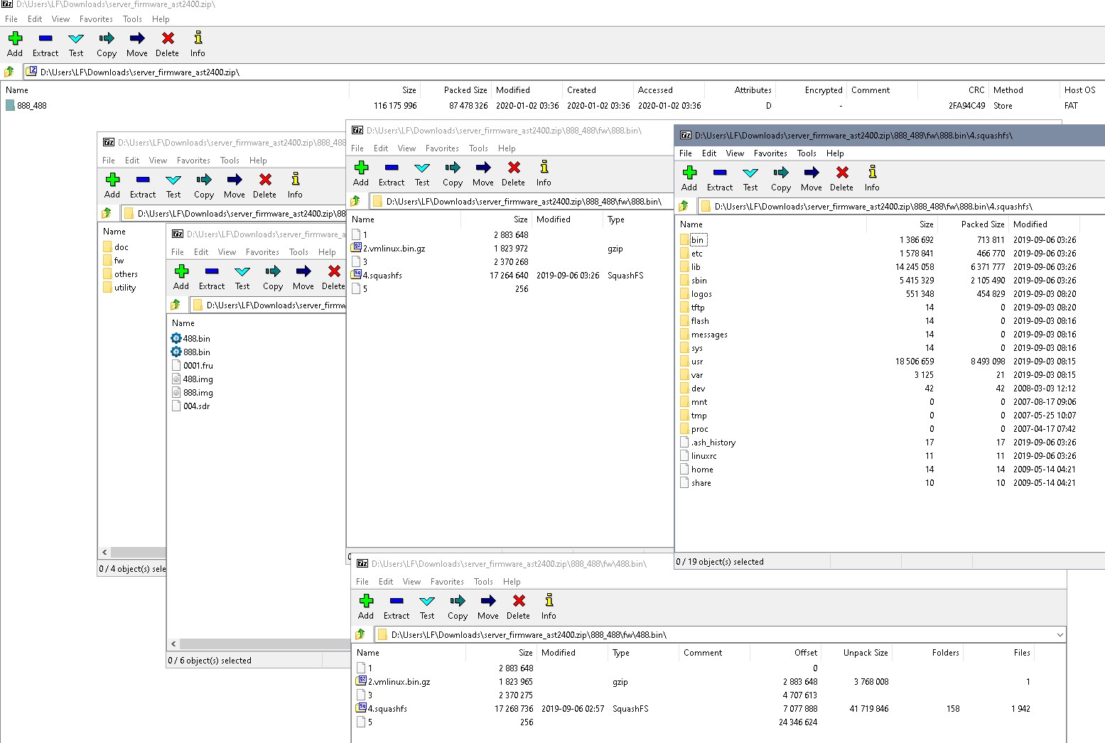
(2) Confusion about v8.88 vs 4.88. Both images are available in the FW folder. After some digging I found that flash.bat required a parameter -128M (uses 488.img) or -256M (uses 888.img).
Then I found an explanation that -128M and -256M were referring to the VRAM size of the Memory Controller for the actual AST2400 processor. So if the VRAM is 128MB then you flash BMC with 488.img, and if it’s 256MB, then 888.img.
Other sources, however, stated that that 128/256 was referring to the size of Flash (in Mbit).

Whatever the case may be, the block diagram of the MD70-HB0 shows this:
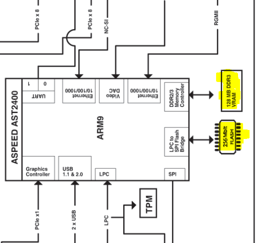
AST2400.PNG


VRAM = 128MB
Flash = 265Mbit

Interestingly enough, when I signed into the original MergePoint EMS that came with datto, it showed me v8.65. Meaning 865.img, meaning flash.bat -256, meaning 256MB VRAM? Is it possible that MD70-DATTO board is slightly different than Gigabyte’s HB0, and has a custom 256MB VRAM therefore 865.img was used here originally? Is it possible to identify the VRAM size by inspecting board visually?

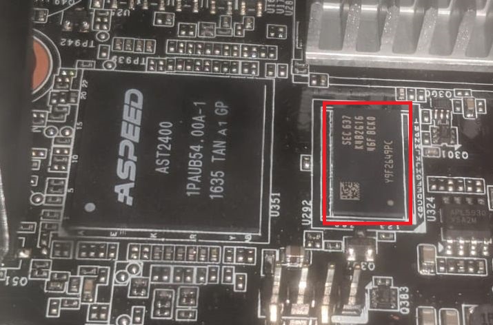
UPDATE: did a visual inspection, located the AST2400 and VRAM:

AST2400.jpg


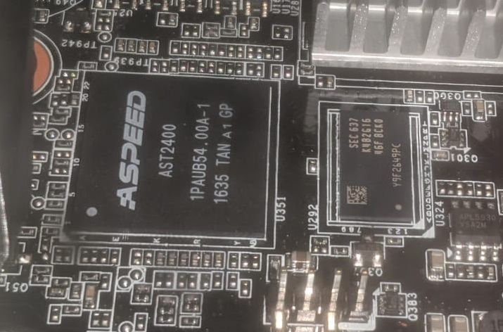
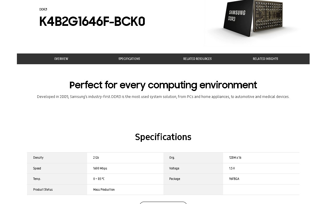
Markings in the VRAM chip: SEC 637
K4B2G1646F-BCK0

Based on the nomenclature, this chip is used for 2GB RAM sticks spread across 16 chip modules, meaning 2G /16 = 128MB per chip. How come I could flash BMC with a firmware meant for 256MB memory (8.88)?

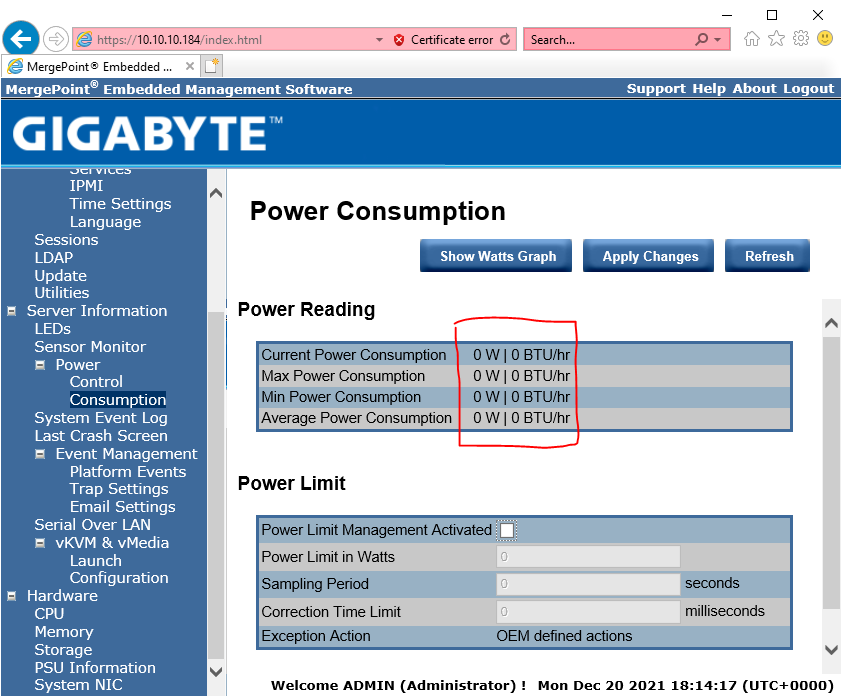
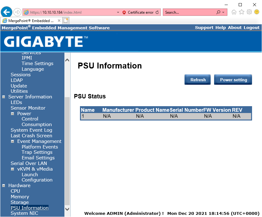
(3) My actual problem. I was able to flash BMC with 8.88 successfully (at least it initiates OK and I can sign in), but I lost some functionality. The new MergePoint EMS (definitely v8.88 but still that persistent datto logo at the top) no longer shows me PSU info and Power Consumption (Max/Avg/Realtime). It’s also not showing me the SAS drives behind the SAS expander backplane, but I am not sure if it did before, but I am 100% sure that I am missing the PSU/Wattage info though, I saw it and played with it before the fw upgrade. Is it possible to get this functionality back?

Sorry for the long read and thanks a lot in advance!

Did I push everyone away from my post by making it too long? I just tried to be detailed and concise… #instantregret

Yes… time is precious, some users dont wast time on situations that requires a lot of effort…not being his problem, sry but it is WOT it is.
Does it seems to u an easy issue?
Doesn’t seem so…at all, just being honest.

Most tech forums get irritated if OP post questions and no additional info. I thought I’d be proactive. I guess was wrong. I’ll break my questions down then. Thanks for the feedback!

Well, one would assume that you’d have done some basic research when working on/ crossflashing a BMC? These images can easily be opened and examined in 7zip:

11.jpg


So that makes it unplausible that the parameter does have somting to do with flash size since they have almost exactly same size.

In addition you can look into the squashfs and you’ll find a folder ‘logos’ here, suggesting that this firmware might be used for many different vendors. According to that the manual for this BMC (“User Guide - Management Console 1.4)” on Gigabytes website mentions a procedure for changing the logo:

12.jpg


So all the logo files are part of the firmware, the logo chosen will be stored in the settings. Since one in most cases wouldn’t like to have the settings reset when upgrading the firmware you still get the old logo…

@lfb6 Thanks for the reply. I didn’t know you could open the image files with 7zip! Great info! Also thanks for resolving the mystery of the persistent logo, it all makes sense now. As for the -128M and -256 parameters required in the flashall.bat script:

1
2
3
4
5
6
7
8
9
10
11
12
13
14
15
16
17
18
19
20
 
@echo off
 
IF "%1" == "-128M" goto MSZ128
IF "%1" == "-256M" goto MSZ256
goto HELP
 
:MSZ256
gigaflash.exe ..\..\..\fw\888.bin -a -2400
goto END
 
:MSZ128
gigaflash.exe ..\..\..\fw\488.bin -a -2400
goto END
 
:HELP
echo Please enter correct parameter:
echo flashall.bat -256M
echo flashall.bat -128M
 
:END


still confusing. If we assume that they reference VRAM size, then I cannot understand why the original installed firmware from datto was 8.65 (implying it was 865.img for the 256MB VRAM) while the chipset on the motherboard (confirmed visually, update in OP) as well as mobo block diagram says it has a 128MB module? How is that possible? Any pointers would be greatly appreciated!

As for the "basic research" remark, I think you are not being totally fair. I did do basic research to the best of my abilities and initial knowledge as a starting point. Asking for help was a part of it, not because I am lazy, but because I was stuck, to the point that I wasn't even sure if was asking the right questions. I realize that things like 7zip is an easily searchable, truly basic knowledge. But you'll never find it if you don't ask google the right question. Having known that fw image files are just like containers, I would have known better. Now I know thanks to you. If the community can point me into the right direction, this will be just as helpful as providing the final answer.

All the best and thanks again!

Manual for the board states 16 MB VRAM for the AST 2400, there are other boards with 8, 16, 32 MB VRAM- not more. AST 2400 specs list "SDRAM Memory, …, Up to 512 MB, ECC option"

Look into the older firmware, there’s a recovery list with script to find out DRAM- size. In addition there are word-files listing different projects for the different versions.

@echo off

KCS b8 20 a 3c 0 24 0
read 1e6e2070 > hwstrap.reg
memsize hwstrap.reg

IF ERRORLEVEL 2 goto MSZ256
IF ERRORLEVEL 1 goto MSZ128
goto ERR

:ERR
echo Unknown DRAM Setting on BMC

:MSZ128
echo Recovery for BMC with 128M
socflash cs=0 if=…\fw\486.bin
goto END

:MSZ256
echo Recovery for BMC with 256M
socflash cs=0 if=…\fw\886.bin

:END
I think it’s (S)DRAM size- the working memory for the Linux system. If this chip has a separate VRAM (built into the chip?) or if it uses kinda ‘shared memory’ is still unclear to me. Definiteively it’s not flash memory.

I believe the proper wording should be SDRAM, not VRAM. Sorry for the confusion. I was reading off of the block diagram of the motherboard (page 9):

AST2400.PNG


By the looks of it, it’s a separate SDRAM chip and it’s shared with VRAM. Visual inspection confirms that it’s a 128MB module: “2G16” means 16 of these chipsets make up 2GB i.e. each module is 2048/16=128MB.

AST2400-red.jpg


I have no idea how 8.65 and 8.88 didn’t brick BMC. Everything points out that 4.88 should be used…

On a side note - when I open 888.bin with 7-zip, I can only see vmlinux.bin. Am I missing something? Do I need a plugin?

7zip2.PNG

15.jpg


https://www.samsung.com/semiconductor/dr…4B2G1646F-BCK0/

2G = chipsize, 16 = number of lines(organisation)


16.jpg


7-zip help, Menu Items and Shortcut Keys

In the end this boils down to finding one datasheet (DRAM size), and reading the manual and looking into the help file of 7zip (unchanged logo).

OMG, I was trying these 7-zip shortcuts while already inside the 888.bin. 
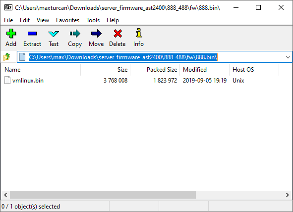
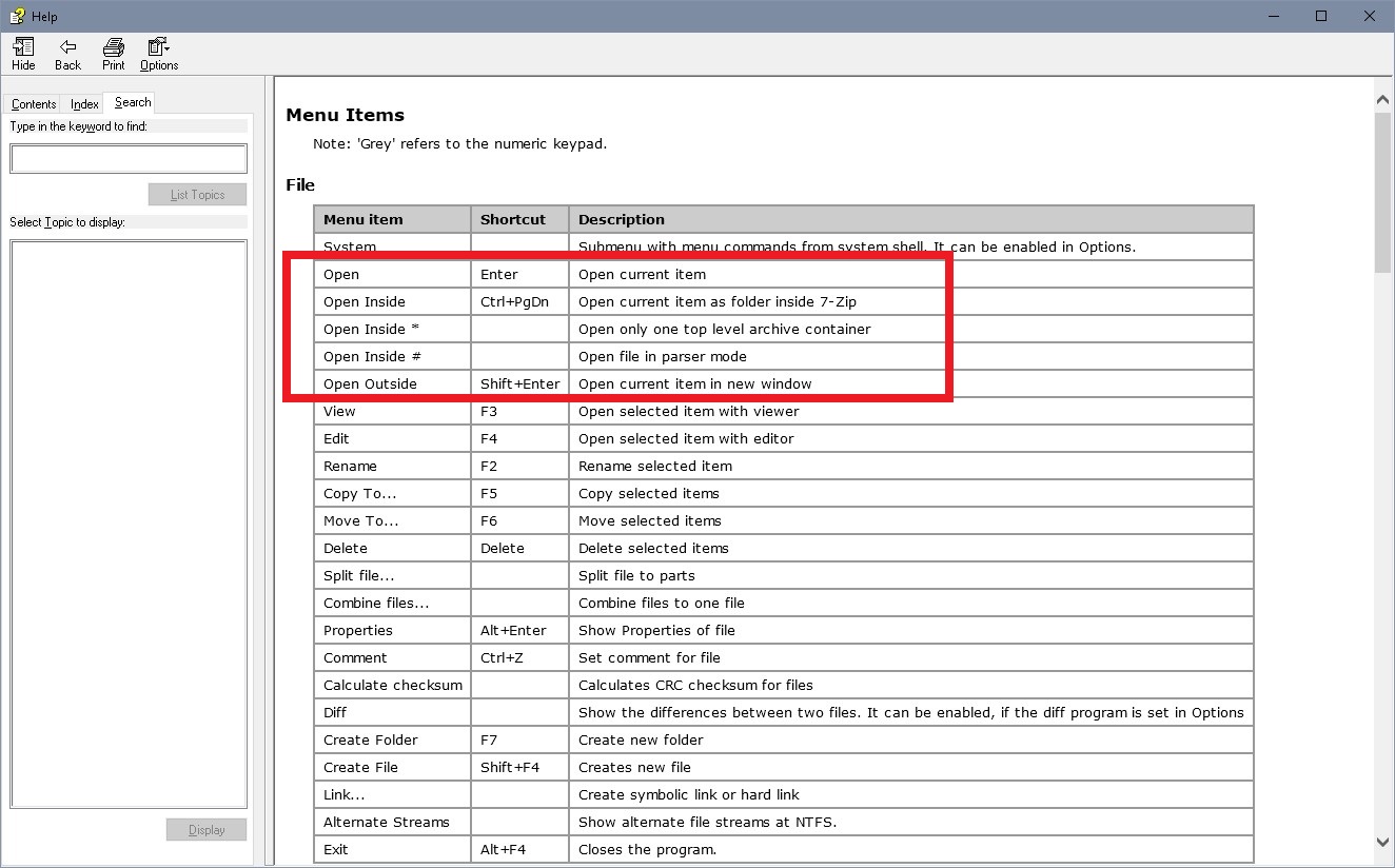
Live and learn… Thanks! Open Inside # (parser mode) worked like a charm.

I used that Samsung website with K4B2G1646F-BCK0 specs as reference too. But the way I understood it, was that this chipset was one of the 16 modules (128MB each), that altogether constituted a ram stick of 2GB. It never crossed my mind that the chipset alone could be 2GB in size and it’s own internal organization was 16x128MB.

Damn it. 2G is 2Gbit!!! Not 2GByte! That is exactly 256MB! Alright, 2 mysteries solved!!!

Although I still don’t understand why the block diagram of the motherboard clearly states DDR3 128M. But whatever :slight_smile:

https://www.samsung.com/semiconductor/gl…_M_Rev1_0-1.pdf

Ok, I thought this was clear. Never seen bytes in chip numbers, and never seen riddles like 16 of this chip gives 2GByte.

Well, if something is just working fine and doing everything as it should, then things might simply be as they should be and you really don’t have a problem


I completely misinterpreted the markings on the chip. For some reason I thought… nah, forget it, it’s so embarrassing that I won’t even say it…


I have one last thing that’s causing me grief, some missing functionality after flashing. Maybe you could point me into the right direction?

After flashing BMC I lost Power Consumption data. PSU Info is also N/A. I can confirm that I was able to view consumption data (real time too) before the update.
Is it possible that the original FW had some custom configuration on the top, enabling connectivity with PSU for reporting?

PSU: SuperMicro: PWS-1K28P-SQ (2x redundant hot swap)
Chasis: SuperMicro 846BE1C-R1K28B
https://www.supermicro.com/en/products/c…C846BE1C-R1K28B

For the life of me I cannot find any firmware for this PSU. I will be contacting SuperMicro to check.


There’s a PMBUS- jumper and PMBUS- connector on the board. There’s not much hardware to configure otherwise…


Thanks! I’ll keep digging in that direction! Something in the new FW obviously doesn’t read the PSU data.

I have the same motherboard in a datto siris. You need to try and flash the BMC again. It took three times for mine to work properly but now everything shows as normal.


Hi Eric,

Thanks a lot for chiming in. I tried flashing BMC at least 10 times, not only v8.88 but earlier available: 8.86 and 8.85. No change. I’d be infinitely grateful if you could share more details about your current BIOS, BMC and SAS firmware.

For me, the BIOS is at R13 (original from Gigabyte, released on 12/05/2019), BMC is 8.88 and SAS flashed to IT mode using P16. The issues with missing PSU data occurred before SAS was flashed, so that’s not a variable, really.

How did you flash the BMC? From within its MergePoint web access or DOS/UEFI boot? I did mine via MergePoint.

So my understanding is that you can see Server Info > Power > Consumption metrics with the latest BMC firmware, correct? Can you see the Hardware > PSU Information too?

Thanks and happy holidays!

Were you ever to get this to work @make-it-easy ? I can pull PSU info via tools like IPMICFG but still can’t get anything to populate in the BMC.