I am trying to flash my BIOS with CH341A and I finding many problems that I do not know how to solve. It is an old Acer Aspire 5920, with a MoBo “DA0ZD1MB6G0 REV. G”. My bios is “Macronis (MXIC 25L8005M2C-15G)”, grabbed on the chip. You can see the technical data in the attached file
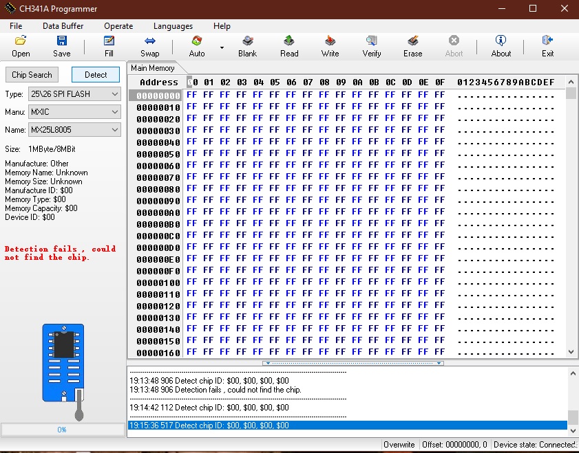
Every time I try to flash with “Programmer 1.34”, first I select the chip type and try to detect it, always with error (as you can see in next image), the same if I try to read the BIOS.
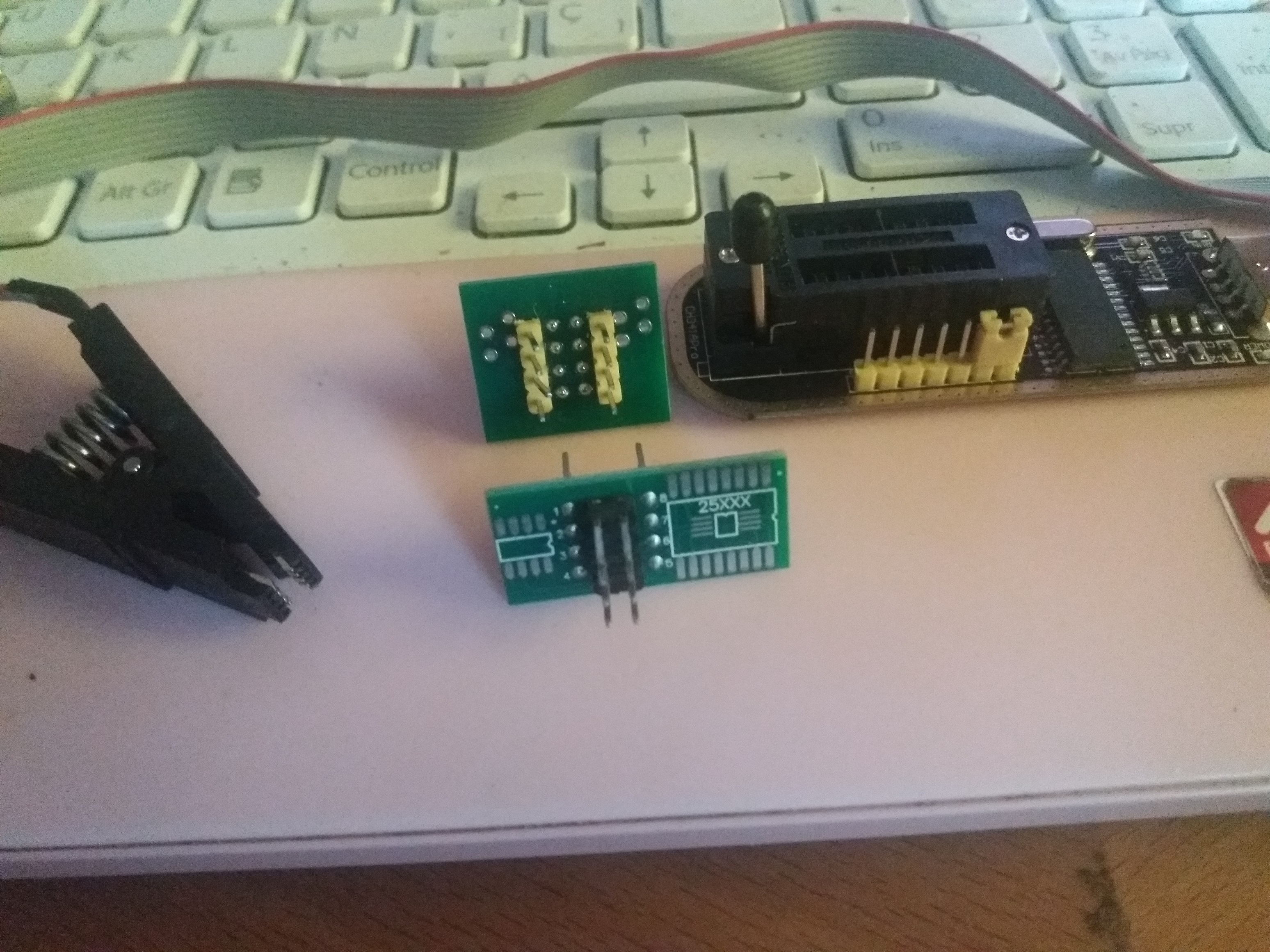
The image is only one of the thousand I changed the position of the dam clip. In my CH341A flasher I have to little PCB, one of it with the 25XXXX legend and the other with the SOP8 legend. Apart I have another little PCB without pins, and those pins separated apart. I connect the clip with the red wire in the pin 1 of the chip and programmer.
I have tried with both PCB, but always with the same result. At this moment I do not know if I am choosing the right chip type in “Programmer 1.34”, or if I am installing in a mistaken way the CH341A, or which can be the problem.
Some idea or help in this moment? Thanks in advance
Then you need to use different software possibly, try 1.18 or 1.30 - http://s000.tinyupload.com/index.php?fil…695330485827902 Are you sure you have it all connected properly, and did you try with and without power connected to the board? Some boards need power connected, some need it all removed. Is this your first time using CH341A, or have you used before?
PCB is only there to help you get correct pins matched up, unless you solder it to the pins it’s really not necessary other than to show you what pins are what # provided you have it orientated correctly. Sorry, I assumed you meant a “loose” PCB, I checked your image and see both of your PCB parts are pre-soldered, so you have to use them (either one = same)
Sorry for the delay @Lost_N_BIOS , I have been really busy.
Well, Looking at the tutorial I have read, I supouse it is connected ok. You can check it in the file with the images. And yes, I have tried it woth and without power.
I am a fully newbie with this… I think the main problem is the dam clip. I am almost unable to connect it . But only by probabilies, with the huge amount of times I have connected it, at last one time it should have worked.
Well connected OK only means it’s connected, does not mean software is compatible or all pins are exactly connected perfect for read/write (it’s tricky sometimes)
Show me images of your BIOS chip on the board so I can see what pin is 1, then show me images of you having it connected to the chip, and how the cable is going into the programmer. Sorry, didn’t notice your links until I posted this! 6MB Per image!!??!! Looks OK, provided red wire is going to pin 1 on the chip.
Did you try 1.18 software? How about ASprogrammer, have you tried it before? Here, get 1.41 - https://github.com/nofeletru/UsbAsp-flash/releases/ This chip you mention is 512KB, usually BIOS is larger, but I’m not sure how old this system is. Can you please link me to the latest BIOS from Acer so I can check the BIOS size, you may be trying to dump wrong chip anyway
The BIOS file is 1.05 MB, larger tha 1MB (1.048), that is my first problem. When I select the chip in Programmer or ASProgrammer (SPI 25/26 -MXIC Manu- Type/Name SPI-MX25L8005), apart to not detect the chip, the soft says it is 1Mbyte/8 Mbyte and the BIOS file is larger than memory.
I have tried all Programer’s versions. I will check ASprogramer 1.41.
The pin 1 is the one were the red wire is connected in the images, and grabbed on the chip is the legend (MXI-15G 25L8005M2C). I will tray to get a photo of it, but the letters are truly tinny.
I thought you would need to look very close to the image
Thanks! Yes, that chip you are trying to dump is not the correct one. BIOS chip will be 1MB chip (Something with 8Mbit in ID) No, I can see everything fine with even a 100-200KB image, doesn’t need to be 4K image Show me images of the board front and back and I will help you locate the BIOS
Then I do not undrestand… In the link you gave me, it is just the same that is grabbed in that chip:"QUANTA ZD1_MX25L8005M2C"
Fo the images of the MoBo I attach the service manual. In the bottonn view you can see resalted 14 and 15. 15 is "U10 Winbond" and 14 is "U11", and it trully seems the BIOS chip.
@Haplo - I do not understand this sentence >> In the link you gave me, it is just the same that is grabbed in that chip:"QUANTA ZD1_MX25L8005M2C" Sorry, if you meant that is 1MB / 8Mbit chip, when I looked up before I was seeing infrom from MX25L400 and didn’t notice that until now, so yes, that is correct chip you mentioned.
Did you write BIOS I gave in first link yet? If that fails to work, let me know and I will grab one from geekdais for you
The problem is that neither Programmer or ASProgramer detect my chip. It is very strange… The CH341A has 2 red lights. One is on when the CH34 is connected to the USB port, and the other is of certain times when connect the clip. Does it mean, when this second light is on, that the clip is ok connected???
If so, the problem is that when the second light is on, the USB prtogrammer is disconnected (not recognized by Programmer), and if the light is off, the CH34 is still connected, but any soft can detect the chip.
[[File:Sin título.jpg|none|auto]]
Her you can see the problem. In this case the second light is on, but now CH341A is not detected (it is disconnected)
@Haplo , have a look at your wires connecting to the top of your clip, to me they look terrible. Are they just wrapped on or are they soldered on, they look like they could be touching. Use your clip on another chip. Get an old video card and dump its bios. Usually small motherboard like video cards don’t need external power. Try to prove that your clip is functional. The way I did mine, I soldered the connections and then heat-shrinked each pin terminal on the top side to make sure I got a good connection.
The second red light is only on when it’s properly connected and reading or writing (bright LED like power one), sometimes if partial connection and doing nothing, it can be dimly lit. Good connection, and not reading or writing, it’s always off
 . But only by probabilies, with the huge amount of times I have connected it, at last one time it should have worked.


