I was working on a Lenovo Thinkstation P710 with a corrupted BIOS. A wrong bios update was performed via windows and since then it gives out a black screen.
I have a CH314A so I took a dump of the BIOS, it’s a 16MB ROM, I’ll attach it here.
So I really don’t know how to get a bin file that I can flash back using the programmer, if any of you knows how to fix my corrupted dump or can find a functioning 16MB bios, it would be amazing!
I’ll tag @Lost_N_BIOS as you helped me a LOT back in the day when I was working on the LGA 1151 mod for Coffee lake on Z170, I still owe you one!
Thanks in advance to everybody, it’s very nice to know that a forum like WinRaid exists
I don’t know how to thank you mate, truly a great job I was absolutely certain it was corrupted somewhere lol.
I really do love tech and I’ve explored pretty much every possibility in the past years, but I’m still very noob-ish when it comes to bioses. Could you recommend me a way to start to really learn about how to work on corrupted bioses, cleaning the NVRAM and accessing the ME? I’d love if you could teach me a little
Thanks for the feedback, glad to hear it worked. Since there were two changes combined (reinitializing ME and emptying NVRAM) it’s unclear where the fault was. No visible corruption both areas…
Cleaning / fhreshly initializing Intel ME:
About the NVRAM- there are some posts here and a lot of posts, but this depends on bios manufacturer and version, there’s no ‘general rule’. Take a look into the files with UEFIToolNE and compare them with HxD, it’s actually not much I did change!
@ItxLeo
That exact same thing happened to me, guys, guess I will need to buy myself the BIOS programmer, which one did you use, please? Did you simply flash the new enme file contents to the BIOS chip after clearing it? Which of the many chips on the P710 motherboard is the BIOS chip, please? Thank you so much in advance!
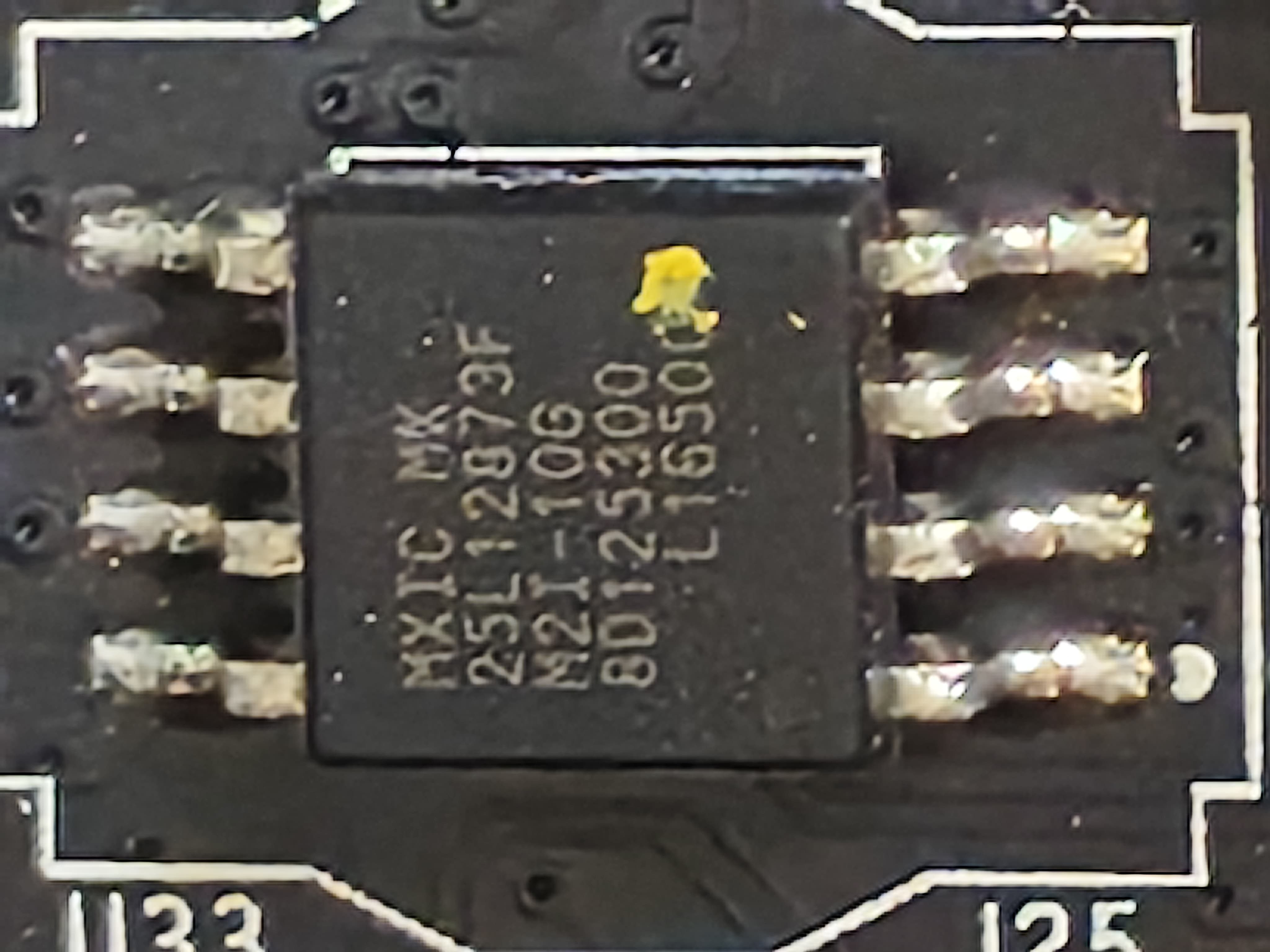
Edit: I found two NOR flash chips, MX25L12873FM2I-10G and MX25L8006EM2I-12G, it seems the one you are talking about is the MX25L12873FM2I-10G one, which has 128 megabits, right? What is the MX25L8006EM2I-12G for? Could that one be corrupted as well? I got myself the programmer, I will try comparing stuff when it arrives. @lfb6 In case you did not get a notification, I will tag you here, thanks again!
@lfb6
Thank you very much for your reply, yes, it is probably exactly the same problem, I mean, at least the circumstances sound too similar to dismiss it.
I got myself a second hand P710 and during a windows update I selected the optional updates along with the obligatory ones, I got like 5 or so that needed a reboot and I remember one of them being a firmware update, even though I have already successfully updated the BIOS manually to the recommended xxx72A before via the Lenovo support automatic updates and everything was working well after that reboot.
However, after the windows updates reboot the BIOS got bricked, the PC just powers on, no signal to the display, no diagnostic LEDs, no beeps, only fans spinning and it shuts down within a minute, tried the BIOS block recovery update via the clear CMOS jumper and a burned BIOS ISO update on a CD-RW as described in the user manual but it didn’t work, the CD-ROM span for a few moments but the PC shut down again as always. I did the burning via the burn to disk menu option with verify checked and stuff, I believe the problem is elsewhere…
In any case, I ordered myself the black version of the ch341a programmer, it will be delivered on Monday or Tuesday I believe. I will dump the current BIOS bin file and post it here. Btw, I have seen people arguing about doing the 3.3V mod and not doing it because 1mA won’t fry a chip, I am not sure what to make of this, I have almost zero soldering experience, so I hope the mod is not required.
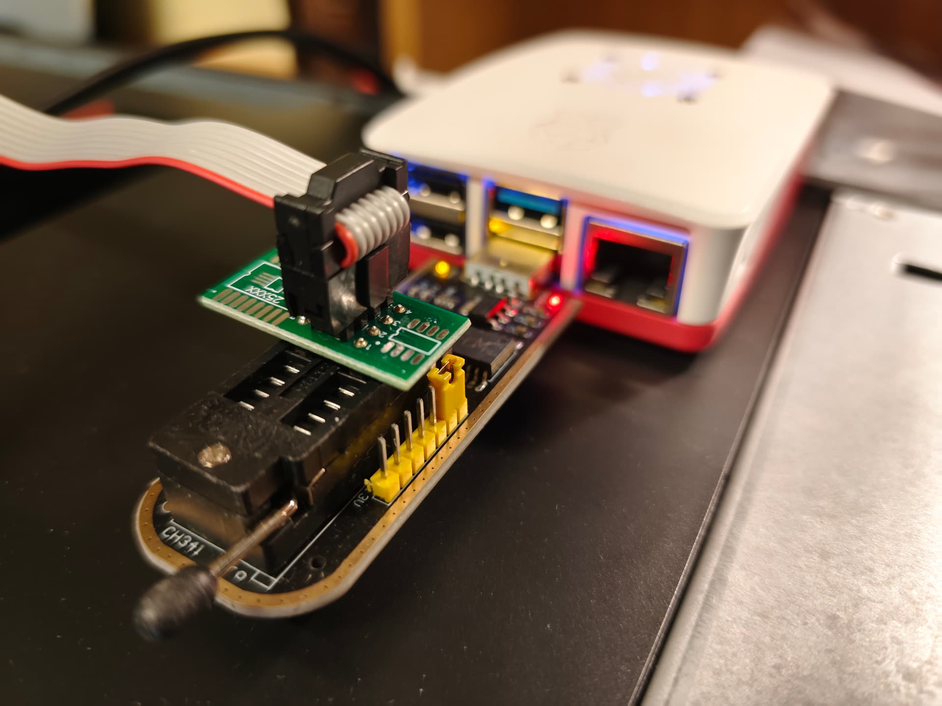
I have tried reading the BIOS tonight, the PC was unplugged and the CMOS battery was out, I have also took down the CMOS jumper, at first, when plugging the programmer into the PC (raspberry pi 4), it gets detected and works with flashrom, saying probing for the chip I select via -c argument and stuff. However, as soon as I connect the clip to the chip, the run LED lights up in orange color and the programmer gets disconnected from the USB bus, although the LEDs are still on, the device won’t respond until manually plugged out and reconnected again. Am I doing something wrong?
Edit: I have seen in another thread a guy that tried three different clips until it worked. Someone even said something about some models being wired differently than shown on the pictures, should I try to connect it in different orientation? I have checked the way I have connected it with the guides here at least a dozen times, though… Also, should the CMOS battery be installed, or the CMOS jumper on or the PSU plugged in or something? It feels like that’s a bad idea, but I read on a different thread that the programmer is unable to power the chip and the motherboard sometimes.
When RUN led lights up as AMBAR/RED, there’s a short in the connection…only should lit when operating.
It’s very “touchy” for new users with no experience, to use this device, the main culprit is the cheap clamp that comes with it, the device itself is fairly useable.
The red pin is PIN1 to the IC, its ok in the CH341A as seen in picture, no other orientation is to try or will short/damage device or IC.
Rare are the cases, generally only in laptop, thats needs additional PSU standby or CMOS battery, default is all OFF.
Get the PDF of the IC model and check it (MX25L12873FM2I-10G)
Backup all the ICs. CMOS jumper stays as default position.
Attach picture of the ICs identified, if possible, for future users’ reference dealing with this model/motherboard.
Thank you very much for all your advice. I have since tried many times to read the chip but to no avail… Every single time I feel I have put the clip on the chip properly the RUN LED starts to glow and the device gets disconnected. I have even bought the blue clip, the Pomona 5250 SOIC-8 test clip for 20$ and although I must admit, that it feels a bit better to work with it, the results were the same, I have now concluded that the problem is somewhere in one of the following tree places:
The CH341 Programmer itself, since it’s my first time using it, I might have gotten myself a broken one, or it could have broken during delivery.
The BIOS chip itself, but I am unsure whether a firmware update could have caused the entire chip to fry or something, it feels unlikely but I cannot overlook the possibility.
And last but not least, something else could have broken on the motherboard, what else could have recieved a windows firmware update, though? Isn’t it usually only the BIOS chip getting such updates?
In any case, I have ordered the following items to do some more tests until I decide to search for some professional help: 5 pieces of new BIOS chips (MX25L12873FM2I-10G), a few sockets for BIOS chips in case I have to desolder it, I plan to make it so I do not need to desolder it the next time, and a new green CH341 v1.7 programmer. I will report back once the goodies get into my hands. Thanks again!
Also, here is a close up photo of the chip in question, there is also a free spot with 8 pin plates where the backup chip would have been, I am thinking of setting them both up in case something would happen to the first one, does anyone have any experience with that? Can I simply put two identical chips next to each other? I mean, it should probably work, right?
Sorry but i cant help more on this as i dont have such system, pity that the user @ItxLeo couldn’t give some tips here.
When a system give such issues, i usually desolder the IC from the pcb.