[Need help] Reviving bricked Gigabyte B450M-DS3H after bios update

Hey guys I’m very much a newbie with these sorts of things so bear with me. I have a Gigabyte B450M-DS3H V2 motherboard that was working just fine until I tried to update the bios to the latest f62d version (I would normally avoid doing this but the Gigabyte website mentioned critical vulnerabilities discovered in earlier bios versions and strongly recommended updating). The bios update using Qflash seemed to have completed successfully and showed no errors of any sort but once it restarted the PC would not boot anymore and I heard 3 long beeps (everything turns on and the fans spin up but nothing on screen and cant get to bios settings or do anything). I went through the usual troubleshooting of disconnecting everything, switching display, gpu, trying every single combination of Ram sticks and slots, tried with only one stick and even got different ram from another computer but to no avail. I either get the 3 long beeps error code or nothing at all depending on which ram slot I’m using and never anything on screen.

At that point I figured my MOBO Bios was somehow messed up during bios update so I got a ch341a programmer with the clip and have been trying to flash a working bios downloaded from the Gigabyte website. My issue is that despite trying multiple programming software (Asprogrammer, Neoprogrammer, Colibri) none of them seem to be able to detect and identify my bios chip which is the Winbond 25Q128JWSQ (picture attached). I tried manually searching for it on NeoProgrammer and the closest model I found was 25Q128JW-xM(1.8v) and after selecting it I am able to read the contents of the chip which tells me the actual physical connection is fine, but once I actually try to flash the gigabyte bios I get a bunch of errors on the verify stage and it stops right away.

It seems I’m out of my depth at this point and would really appreciate any help from more experienced folks. Thanks in advance.

PS: I also attached the dump I did of my bricked bios I did with Neoprogrammer after manually selecting 25Q128JW-xM(1.8v) although I’m still not at all confident that’s the same chip.

IMG_20220202_210710.png

BIOS.zip (470 KB)

No, I don’t think you’re able to read the content of the chip, that ‘dump’ has no structure at all and looks like a constant read- error, starting with some recurring signs and getting almost completely “0” to the end.

You did mention that you got a CH341 programmer and that the chip is 1.8V, so I assume you use a 1.8V adapter??

Either you can establish better contact to the clamp, work with CMOS battery or power on/ of, find a SPI header or get the chip desoldered. Rule of thumb is- if you can’t read properly you can’t write properly…

I am having a very similar problem. It’s a Gigabyte B450M-DS3H. Went to update the BIOS from Gigabyte website and when it restarted, there was nothing but a blank screen. Everything turned on except there was nothing going to the USB ports or the HDMI port. So I bought a CH341A programmer, downloaded ASprogrammer, and was able to detect the chip, MX25U12873F. Now I don’t know which file I am supposed to be using to program the chip in ASProgrammer. I downloaded the BIOS from the Gigabyte website and changed the file extension to .bin. Then I opened that file in ASprogrammer and selected UNPROTECT->ERASE->PROGRAM->VERIFY…it erased the chip, and began to program, but then it stop after a few seconds and says at the bottom VERIFICATION ERROR ON ADDRESS: . Can someone please tell me what I need to be doing? I’m not entirely sure that I’m opening the correct file to program to the chip. I’m also not sure that I am doing this in the right sequence. Any help would be greatly appreciated. Thank you.

I realise this is a bit after you have had no reply, but I find myself in the same situation.

I’ve managed to identify best I can that I have the same board and flash chip as in your example. It failed due to power off during flash to F63c using QFLASH (around 40% complete I think) boot was no output or anything, tried CMOS reset and could not get boot.

Been unable to get a read (other than FF) or anything - seeing now that power to the board may help. I have no CPU or RAM to assist me, was just hoping I could get communication to the IC and try to reflash. Convinced I have a connection to the chip just wondering if you needed to power to get anywhere.

I do have the board SN and MAC


Try to use cH341a programmer ver 1.18 or 1.29

my z68 board got error using asprogrammer, but using ch341a programmer 1.18 it worked…

also during my attempt on reviving the board, programmer cant detect the chip, until i unplug the cmos battery, and let psu on (mobo receive power but i took off cmos battery, so no cmos but mobo still get power from psu), and i press detect, it could identify the chip.

Primarily, the CMOS battery 3.3v will provide current to the SPI circuit, if not then PWR standby. CPU or RAM out shouldn’t be an issue here besides testing.
A well established connection to the SPi by direct contact its a bit tricky, but it should be ok if the soft correctly identifies the SPI ID, you may need to try several soft apps to deal with it.
As lbf6 stated, last resource taking out the SPi from mainboard and soldered back.

Thanks for the reply. I have been using ASProgrammer 2.1.0.13

As far as I can tell, the CH341A (black) is in the correct mode (jumper 1-2), correct IC position (25SPI), I have the 1.8V adapter in situ and connected correctly. Pretty sure I have the clip on tight and on Pin 1, will try the software version recommended. (However I don’t think it has the chip selectable, ASProgrammer does), it doesn’t detect as yet.

@MeatWar thanks for the tip about CPU, RAM etc.

I will try the CMOS battery out as it is an unknown and introduce standby PWR.

No, any soft WILL have to ID the SPI, if not then its the tricky part i told you, it may look well seated but its not communicating with it.
Some apps may not have the SPI ID on their database, thats the other main reason besides correct voltage to the SPI.

1 Like

yeah, make sure every pins and clip are seated correctly, took off cmos battery, power on psu, and try to identify using ch341a programmer (try from ver 1.18-1.31, make sure the chip is correct (if it only shows the MB of the chip in the programmer, then calculate the chip size to MB/Mb, for example 64Mbit is 8MB, in your case, yours is a 128Mbit chip which means 16MB)

1 Like

Yeah NeoProgrammer is showing IC not connected :smile: At least that is progress, I’ll try to reconnect and detect until I get it.

Board is now on standby PWR as well.

Yeah I can “spark” the board (PSU fan on) and with CMOS in/out…no connection to IC. Board won’t power down closing and holding PWR_SW (screwdriver).

I don’t have the soldering skills but I am at a loss as to why the board shut off during reflash. It was being revived with a new PSU after a confirmed PSU failure. I had to reset to get to QFLASH but display was going blank (external GPU RX5700) and CPU 5600X. Once I reset it seemed stable, loaded CMOS defaults went into QFLASH and that…was all she wrote.

Thank you both for your help.

Tried CH341a v1.31 that at least has detect function but all I get is FFFFFFFF (no connection)

have you sure that your connection is correct? i mean pin to pin (if u use soic8 clip make sure the red marked cable is touching pin no 1 on the chip), and do make sure that the contact pin touches the pin on the bios chip completely.

So with board powered by psu (usually board wont turn on without cmos, or it would turn on with ch341a connected since bios chip get power from ch341a programmer) and cmos off, it should be able to get a read if connected correctly

Oh also i forgot to tell you this, but i use Dell laptop that i rarely use, some usb port wont work but there is 1 usb port that work (yes, once the usb port worked (chip detected), i try to unplug and plug it to the usb port next to it and the one on the other side). so try change to anotherother usb port

Also you did install CH341PAR.exe driver before using ch341a app? the thing that get me to work on reading the bios is that i need to move to another usb port that could read the programmer (and the bios chip), install ch341par driver, then use ch341a 1.18 or as high as 1.31, with cmos battery taken off and psu switch powered on. it detects my bios chip afterwards

Yes. Pin 1 indicated by dot on IC and small arrow on mainboard. Red pin to that. Tried many times. Using USB 2.0 ports as advised, Both work fine. Tried about 30 times to seat clip to IC without success (read).

Each time IC no response. Tried in NeoProgrammer, CH341a v.1.18, v1.29 and v1.31 just 1.31 has detect and set to 16M as advised. IC no response or FFFFFFFF

Read gets FF but if you can’t read you can’t write.

Was only a try to recover a board that failed inexplicably. Can only assume flash IC is U/S or mainboard damaged.

Mainboard will power on with or without CMOS battery just obviously no CPU or RAM no bleeps as that would be a UEFI

I don’t want to be a party pooper, but we’re aware that the first 128kB (0x20000) of this firmware normally really are “FF”?

You did scroll a little (actually quite a lot) longer down or opened the dumps in UEFIToolNE?

(And at the end there’s even more of FF, too)

1 Like

Thanks, yes I did. I loaded the actual image into the software as a control just to check there wasn’t some random bug :smiley:

But thanks. And tried a ‘blind write’ when I got desperate. It’s good of you to think of the schoolboy errors.

Could it be anything to do with the un/locking? Board was already on F60x or F61x before attempting the flash so that would have SMM or hardening.

Must confess to not really understanding how that is implemented and was under the impression that flash programmers kind of got around these things. But it might prevent a read? Or a write? Looked at it in the software but again everything was FF but I didn’t understand what to select or even if it is important?

No offence meant! But I’d like a solvable situation caused by a maybe stupid sounding error much better than not knowing what to change to overcome the errors.

But if you tried to write you’d have to erase the chip. So maybe the content is really FF now? Sometimes erasing works but writing doesn’t…

What chip is this? Did you search the forum for the type?

It’s in the attached photos if you zoom in - MX25U12873F

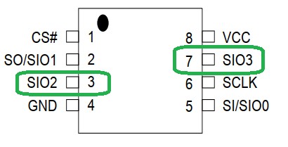
Try to use only necessary pins- disconnect 7 and 3 on the clamp

55551

No warranty, though, but sometimes this helps when they had funny ideas and / or the chip draws too much current. I don’t like that little resistor maybe connecting 7 and 8 (can’t see clearly on the pics)

Tried ASprogrammer 1.4? Might work with MX25U12835F chosen?

Disconnecting pins comes from this experience (necessary pins 4 posts down):

I happen to be helping a friend with a rather similar (But not identical) Gigabyte B450M DS3H WIFI, which has a Macronix MX25U12872F. He had the exact same issues about not being able to read/write and getting only FF FF.
After some datasheet reading, it seems than the MX25U12872F is cross compatible with the Winbond 25Q128JWSQ so most likely both would behave the same, at which point I noticed in the datasheet that both are hardwired to “Quad SPI” operation, which is what I suspect to be the true culprit.
Based on this post from other forum, the CH341A is not Quad SPI capable: CH341A Serial Memory Programmer Power Supply Fix - Page 3

Some further googling got me here:
https://www.downtowndougbrown.com/2021/12/upgrading-a-motherboards-bios-uefi-the-hard-way/
Which seems to make a CH341A mod for both 1.8V (Not needed he has the adapter) and Quad SPI.

So: Do anyone here with similar experiences can confirm if Flash EEPROM chips hardwired for Quad SPI need special support from CH341A and flashing Software? This seem to be a trend on Gigabyte AM4 boards.

1 Like