Hi,
I’m trying to mod the bios for the J4205-ITX board
With UBU I get:
Scanning BIOS… Please wait…
Unknow Versiom AMI Aptio
and UEFITool gives me an error:
---------------------------
Image parsing failed
---------------------------
Invalid UEFI volume
---------------------------
OK
---------------------------
Any idea how to proceed here ?
Thanks
Already discussed here, there’s a bug in descriptor configuration of that file. Use MMTool 5 or PhoenixTool to work with it.
Or fix it manually and verify via UEFITool like CodeRush showed me back then. 
It’s always the last BIOS volume which has size problems. It usually ends after the BIOS end. So at an SPI image with Flash Descriptor, UEFITool will complain that it crosses to the next SPI region. At BIOS-only images, it complains that the section ends after file size. Fixing is simple enough, search for _FVH, go to the last one (volume) and check the two sizes which are the same in a different format.
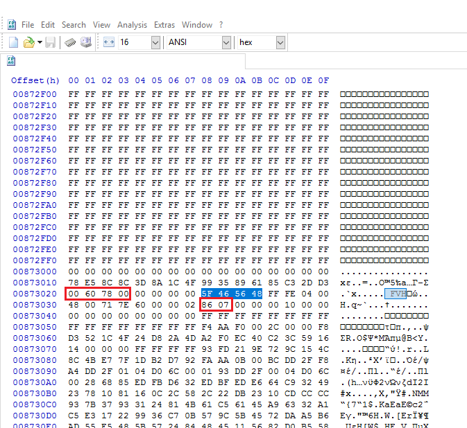
When you have a SPI with Flash Descriptor, adjust the two sizes so that the last BIOS volume does not cross to the next SPI region as mentioned at its Flash Descriptor starting offset. In such case, you must also fix the last BIOS volume checksum. UEFITool reports the correct one after the sizes are adjusted.
When you have a bare BIOS region and want to parse it only (don’t insert it back at a SPI image that way), adjust the file size accordingly instead. In this case (picture, filesize 0x68B000), the last BIOS volume has a size of 0x786000 but the file (BIOS region) ends at 0x68B000, so it’s out of bounds. If you add 0x786000 - 0x68B000 = 0xFB000 padding at the end of the file, the BIOS can now be parsed by UEFITool, MMTool, UBU etc.
Thanks for you help guys.
I found out that the section with was misaligned is the one that contains the ASRock protection.
| Firmware Volume : 05 Location : 00384000 Length : 417000 |
±–±--------------±-----------------------------------±-------±-----±—+
|NO | FileName | GUID |Location| Size |Type|
±–±--------------±-----------------------------------±-------±-----±—+
|000| |414D94AD-998D-47D2-BFCD-4E882241DE32|00384078|00102C|FRFM|
|001| |9E21FD93-9C72-4C15-8C4B-E77F1DB2D792|003850A8|2F4CCF|FV |
|002| |7BB28B99-61BB-11D5-9A5D-0090273FC14D|00679D78|00BFEE|FRFM|
±–±--------------±-----------------------------------±-------±-----±—+
I was able to extract the header and remove the protection by hand.
Now the ASRock security did not trigger and I was able modify and flash the file.
Oh No, after flashing the bios I only get a black screen and system does not boot up.
I’m not sure if it’s because I enabled the DCI option in the BIOS or if the file was coruppted during the modding process ![]()
$150 burned…?
bios updating is quite dangerous…with boards having a safe reflash : no troubles but with others it is better to ask [ may be not here ? ] the mainboard manufacturer or in its forum…
i did asked msi france support …but they are dumbs…so i made a topic at msi forum where they discuss a lot about bios modding overvolting …but not yet TESTING… i made a topic here that has no reply from bios-gurus…[or free-killers…]…[ those whom give advice are not those who refund mobos-dead…]
It’s not that bad. I did a backup of the BIOS before I fashed it and we have a hardware lab at work so I was able to desolder the BIOS chip.
Right now I’m waiting for the new BIOS flasher that is able to handle the MX25U6473F chip as it needs 1.8V and the level shifter I’ve build seems not to work.|addpics|daf-1-3a8b.jpg|/addpics|
i have a tyan mainboard that has a slot for a bios chip . can you tell me the name of it and if you know a usb tool that i could use in case i do a mistake .
i made photos :
http://s23.postimg.org/wevh4lee3/P1140335_FILEminimizer.jpg
http://s23.postimg.org/padnvk74r/P1140331_FILEminimizer.jpg
Sorry it’s impossible to read the name of the chip as the pictures are very blurry.
Just give me the name from the chip and I try to find out what flasher you can use.
i used google and by images , i was able to find something at ebay :
http://www.ebay.com/itm/TL866A-Programme…A-/122246632879
or
http://www.ebay.com/itm/REVELPROG-IS-PRO…l-/301689765851
or
http://www.ebay.com/itm/USB-Programmer-S…s-/121493860355
and a shop that sell bios chips…
http://www.ebay.com/itm/BIOS-CHIP-SUPERM…I-/171062895903
this morning i sent them a email about my biosses : asking them if they can check them or even use some better rom than the one i used . plus i asked about the choice of products to program roms . as my pc are working , i hope they ll give me the right files for few euros .
may be be they can heklp you either ?

The 1.8V adapter arrived yesterday and I was able to successfully flash the chip. I used flashrom on linux for that.
It will detect the chip as:
Found Macronix flash chip “MX25U6435E/F” (8192 kB, SPI).
I found the reason why the modified bios failed. I’m using AMIBCP v5.01.0014 to modify some bios options and it seams that this version destroys something in the image. Now I will try to modify the options by hand to see if that works out.
And I modded the motherboard a little bit for easier flashing ![]()
I tried to just remove the asrock protection and then flash the bios. Same problem … The machine won’t boot. Does someone have an idea what could go wrong ? Signature check maybe ?!|addpics|daf-2-83d9.jpg,daf-3-0a34.jpg,daf-4-e84a.jpg|/addpics|
Yes, BootGuard 2.0 which is new at APL. Until someone knowledgeable investigates how it works and whether it can be disabled (contrary to BootGuard 1.0), you cannot modify such BIOS images.
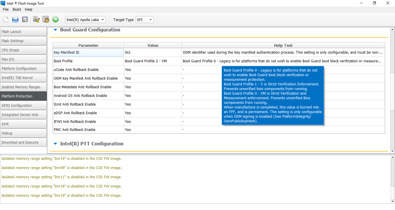
Thanks, that would explain it. What version of Flash Image Tool are you using ?
BootGuard configuration is fused into the PCH by the OEM once and cannot be undone. The Engine firmware is used for the initial configuration and commit to the PCH so you won’t find anything at the SPI image and setting it to disabled at the Engine firmware now will not alter it. You’ll need to wait until people who research BootGuard deal with v2.0 and figure out whether it can be set to disabled for servicing purposes, unlike v1.0 at which such a thing was not possible.
One way would be to get DCI enabled and access the x86 JTAG. Early debugging at address 0 would give you full control of the msr registers but DCI is disabled for this board and that’s what I want to achive with the bios mod. That’s the reason too why I bought this board.
FPF UEP TXE FW
— — ------
Boot Guard Profile 2 - VM 2 - VM 2 - VM
So you were right …
Is there a tool that can edit the Flash Descriptor ? I only find some papers about the reversed layout
I was trying to mod bios on ASRock J3355M ITX board. I have same symptom (doesn’t boot) after bios modding. I am able to reflash via my Bus Blaster and programming header – so board is not dead – but would like to figure out if I can mod the bios successfully.
I am suspecting I probably have same BootGuard issues identified here (?). Was there any resolution to this thread? Or was it a dead end?
Many thanks,
Ben