@lfb6 yes, that finally did the trick. I must have somehow missed changing those "Featured Supported" in the instructions, but doing that did finally restore the MBEx functionality. I had to re-flash the BIOS with the OEM because something went wrong and it was giving me an "Vesa unsupported video card" error, but after that it seems to be working fine.
Thank you for all of the tips and help!
fk
Nice! Glad it worked 
Hello, Ive recently use this forum tutorial, after flashing outimage.bin and restart my optiplex 9020 wont turn on. It orange light without blinking. Pllease help.
Post / attach outimage.bin and the original dump.
this is the link to original dump and outimage
Thank You
You worked on a ME region only- how did you flash it back?
using this command “fptw64 -f outimage.bin” after restart, remove battery, power and service jumper. it stuck on orange light on power button.
last time I remember there are green message that say xx something identical
can this be fixed?
You certainly got a ‘size mismatch’ warning and disregarded it.
fptw64 doesn’t care what it writes where. It compares what it was supposed to write with the content of the chip after flash and gives a ‘task accomplished’ if both are identical. But you overwrote you flash descriptor with the ME thus successfully bricking your system.
You need a CH341a programmer (and possibly a SOIC8 clip and maybe a 1.8V adapter) to flash back your backup.
Thanks lfb6,
where is the chip position that needs to be flashed?
How would I know? I don’t own such a device.
Search the forum and the web, if unsure make a detailed and sharp pic and attach.
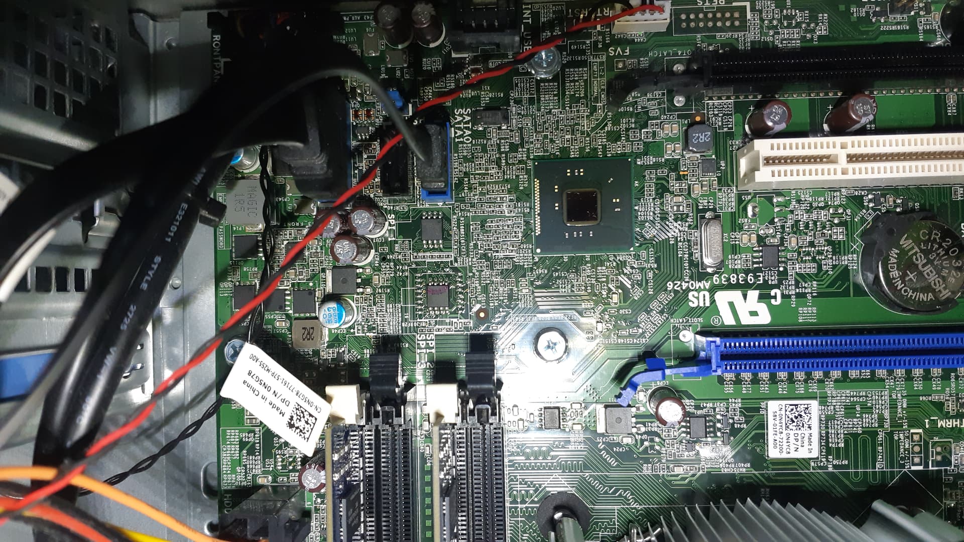
Might be. What’s written on / what’s the type of the chips?
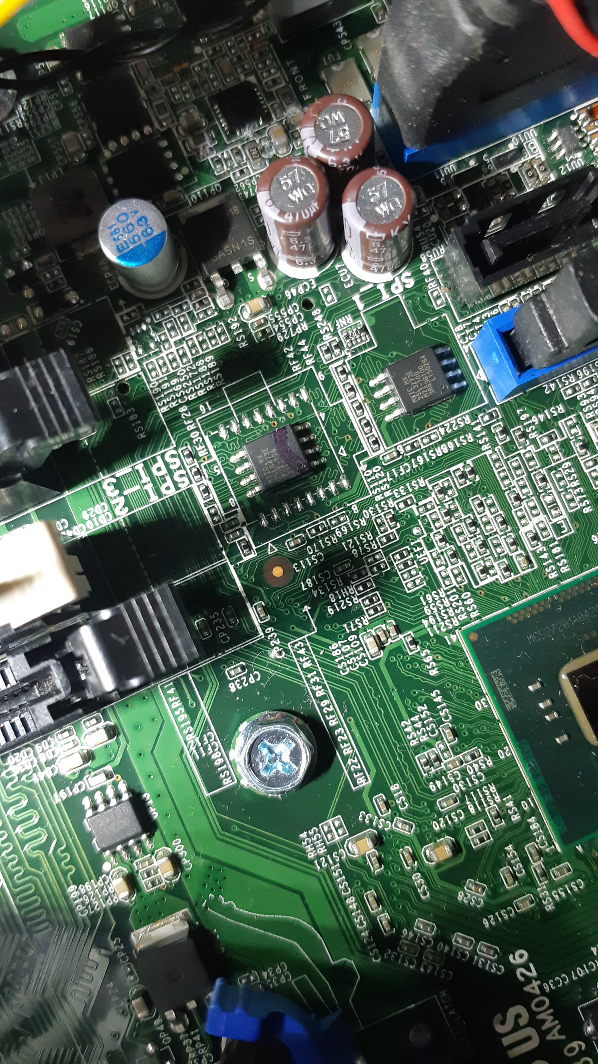
Good picture ![]()
Seems to be the right chips, a 32 MBit and a 64 MBit 3V spi. You need a CH341 programmer and a SOIC8 clip to read them. There’s a lot written how to do that in the forum- for example:
Placing the clip is a pain in the beginning. You need two 100% identical reads of every chip to be sure that your dumps are valid. Compare with HxD or if you prefer to work with checksums: Check in addition the structure with UEFIToolNE (Files with all ‘FF’ do have e nice looking checksum, too)
If you can’t read you possibly can’t write- so it’s useful to read first to be sure that the handling of clip and program is OK (even if you’re sure you have already a valid backup and are sure that the chip content isn’t useful any longer).
Thank You, will update it after getting my ch341a.
Hi lfb6,
Recently I got ch34a programmer and able to read the 2 Chips that I found. They are MX25L6473E labeled spi 2 & 3 and MX25L3273E labeled SPI 1
However when I detect the chip and try to flash, it show backup bin size id larger than IC size. One ic is 4MB and another is 8MB
How to correctly do this?
Thanks
here are the bios dump file backup.zip (6.7 MB)
Please post the 2 files you dumped from both chips.
And there’s no need to post that question in three different threads!
Here are the files. sorry for also post on different threads.
9020-ch341a.zip (6.6 MB)
OK, fptw stopped writing after filesize of the ME region.
The 4 MB chip is unchanged, so you don’t need to flash it.
For the 8 MB chip (MX25L64) take the first 8 MB of your backup (0x0 to 0x7FFFFF - 8.388.608 bytes), save as a new file and flash this file to the 8 MB chip.
OR
If you want to use your own prepared ME region:
Take you old outimage.bin
Open it in HxD (or any other hexeditor)
Fill it with ‘FF’ from it’s actual size (0x4CA000) to it’s needed size (0x5FB000), save the file with a different name
Open the 12 MB backup bin in UEFITool 0.25 or 0.28
‘Replace as is’ ME region with the correctly sized ME Region you just created
=> you get a 12 MB image of the firmware with modified ME region.
Take the first 8 MB of the newly generated last file (0x0 to 0x7FFFFF - 8.388.608 bytes), save as a new file
Flash this file to the 8 MB chip.
OR
If you want to do the changes in the ME config once again with the complete image::
Tkae the complete 12 MB backupfile
Open it in FITc
Do the configuration changes you want
Sace config as XML- file
Close FITc
Replace the ME region in decomp folder with unconfigured ME
Open FITc again
Load the saved XML configuration
Build
FITc will generate one complete 12 MB image and a corresponding 4 MB and 8 MB file
Flash the newlt generated 8MB outimage(?).bin to the 8 MB chip
The last block is a shortened version of
Check sizes thouroughly and check for correct structure / new warnings in parser in UEFIToolNE
If in doubt attach 8 MB file (or all files) before flashing
1 Like
Hi, I tried the third option because the first and second option couldn’t figure out how to cut the file. are first and second option using HxD?
when I open the .bin file using asProgrammer the addresss format is like this 0x007FFFF0 , is this the same as you mentioned?
here are file that build using third method.
outimage.zip (6.6 MB)
outimage8mb4mb.zip (6.6 MB)