@Lost_N_BIOS
Well, I ordered CH341A programmer and started to read “how to use it” because of other problem. My son has an Asrock Z68 Pro3 with sandy 2500K and followed the UBU guide to update the microcode. It updated all microcode and after flashing it, the mobo never booted again.
Later found >this< thread, and realized I must be very careful. I have been worked in a computer shop from 2004 to 2010 and I never made any bad bios flash, except now. So first I must wait for the tools arriving, than reflash the chip and than try to update the Z68 Pro3 latest bios with Sandy microcode only…
I kindly accept help, maybe I made something wrong…
Hello Girjaman,
I’ve made a BIOS with microcode updates for ASRock P67 Pro3.
I made it with HxD & UEFITool. I found special thing: microcodes (mc) has to be in a address sequenz of 800h.
If that not happens, AMIBCP v4.55 couldn’t find every mc. So sometimes I had to inserted 400h of “FF”.
You can delete 400h @ the end of mc section. There are a lot of "FF"s.
Best regards, MiMo
It happens sometimes, even with stock BIOS never modified. Now you will have programmer, so you can fix it all usually. Did you get the SOIC8 text clip cable?
Yes, once your programmer arrives I can update the other BIOS for you too. If you want to send me your modified BIOS that killed the board I can check for you to see if it looks bad, or maybe just bad luck that day and had a bad flash (ie not due to the modified BIOS file)
So … ASRock Z68 Pro3 BIOS v2.16A (minimal safe version)
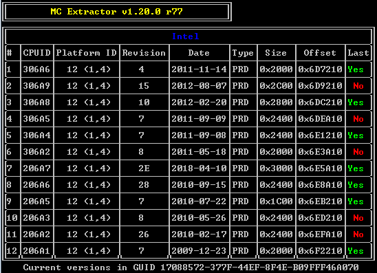
ASRock Z68 Pro3 BIOS v2.16A (default safe version)
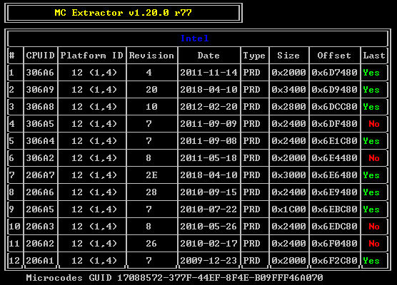
ASRock Z68 Pro3 BIOS v2.16A (-Zen- safe version)
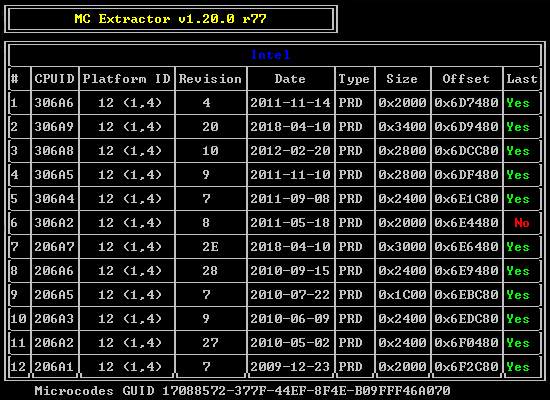
… are patched and updated Sandy Bridge MC + OROMs (p.e. IRST to v11.6.0.1702).
Checked with AMIBCP v4.55 and all MCs where found on correct address.
!!! I can’t give any guarantee/warranty, but i made this by best purposes & knowing. Use/Flash of own risk only !!!
P.S.
Both original BIOS files (v2.10 & v2.16A) has bad checksum. I don’t know, if it’s a bug, a special signature or a “feature”
 . I patched them before and after editing.
@Lost_N_BIOS Being very angry I deleted all files… ![]()
@MiesMosel Thanks a lot for your efforts. The bios - that earlier bricked the mobo and made by myself- I checked twice after MCs update and looked exactly like the above pics. All MCs was green.
[URL=@Lost_N_BIOS Being very angry I deleted all files… ![]() @MiesMosel Thanks a lot for your efforts. The bios - that bricked the mobo- I checked twice after MCs update and looked exactly like the above pics. All MCs was green. In these posts @Dogg supposes only sandy bridge MC (206A7 cpuid) should be updated in the bios file, avoiding sandy+ivy update together.
@MiesMosel Thanks a lot for your efforts. The bios - that bricked the mobo- I checked twice after MCs update and looked exactly like the above pics. All MCs was green. In these posts @Dogg supposes only sandy bridge MC (206A7 cpuid) should be updated in the bios file, avoiding sandy+ivy update together.
/Just fot the record, the latest Intel Microcode Guidance in the desktop line only mentions Ivy Bridge E series Cpus (306E4), others only mobile (306A9) and servers (306E4)/.
I hardly can wait for the tools and try @MiMo’s patched bios ![]()
MCE cannot show correct alignment. It only shows MCs, that were found. I checked it with AMIBCP v4.55.
You can show me your BIOS file, that bricked the BIOS, then I can proof it - if you’ll find it.
regards, MiMo
P.S.
In about one week, I’ll get my BIOS programmer, too.
@Girjaman @MiesMosel @Lost_N_BIOS :
Your posts have been moved by me into this freshly created thread, because Girjaman’s problem regarding the CPU Microcode of an ASRock AMI UEFI BIOS has nothing to do with the topic of >this< thread, where they originally were posted.
I hope, that this is ok for you. Thanks to MiesMosel for his hint.
Lost_N_BIOS said:
Girjaman said:
This programmer looks on Windows like a normal flash-tool combined with an hex-editor:
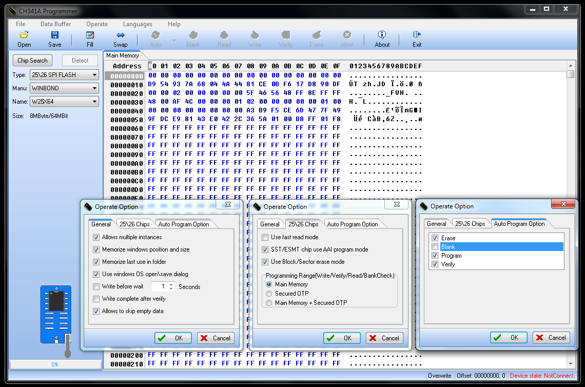
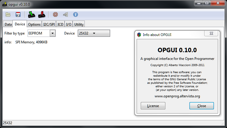
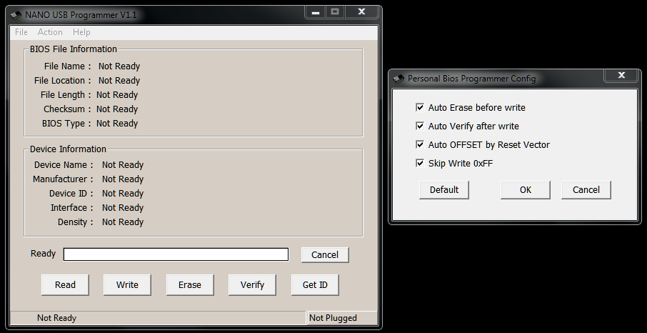
The only requirement is to know the Version of BIOS chip, you wanna flash.
So look first on surface of the chip. If there’s a product label with BIOS version number, then you have to carefully remove it. Don’t scratch the surface.
There should be manufacturer and model designation.
Girjaman said:
Lost_N_BIOS said:
@Girjaman
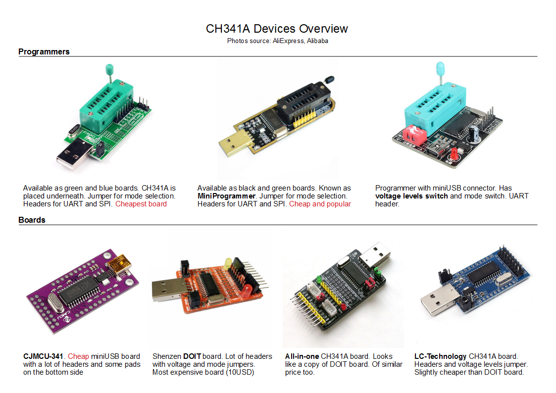
I’ll get the same programmer (black version) & clip cable in the next days.
But there are a lot of questions to do it right. Maybe we should open a new thread for that in the future.
If we know the chip, then we also have to know the voltage (5V or 3.3V or ??) for that.
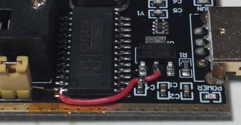
For our programmer there’s a voltage mod to 3.3V, if nessessary. It depends on BIOS chip version.

Hello!
My USB Programmer is here since some days. It seems to be having no problem with Voltage @3.3V.
Chip vendor+series was recognized, then I choosed 1 model of 3.
All versions of Mini Programmer could read the BIOS-Chip (DIP8).
Open & Nano Programmer don’t function with that black miniprogrammer.
The SOIC8-clip-cable is too thin, so I wanna buy an additional DIP8-clamp/cable.
And I found out the best driver for that USB Mini Programmer (black version) → driver-- 24CXX25XX.EXE
Inside there’s a WDM driver for Windows 98/Me/2000/XP/Server2003/Vista/64bit Vista/Server2008/Win7/64bit Win7 v2.2.2009.06 from 06/05/2009.
In device manager there’s a new [interface] driver called “USB-EPP/I2C… CH341A” → hardware IDs: USB\VID_1A86&PID_5512
I don’t know at the moment, which driver works on Win10.
regards
driver-- 24CXX25XX.zip (136 KB)
CH341A Programmer v1.29.zip (4.39 MB)
Thanks for your info @MiesMosel and driver. Why do you feel it’s best driver vs CH341SER.EXE (Serial mode/cable usage) & CH341PAR.EXE (Program chip mode) from manufacturer like these - http://www.wch.cn/products/CH341.html
Please link to new better test clip cable when you find, thank you!
Hello Lost_N_BIOS,
"CH341SER.EXE" didn’t work for, because of different hardware IDs. It could not recognize my USB Mini Programmer @ Win7 64bit.
"CH341PAR.EXE" works, cause it’s the same driver as "driver-- 24CXX25XX.EXE" -> v2.2 from June 2009.
Yesterday I only found some @ aliexpress.com or so for around ~10$ or€(?).
To find it in europe … … … I hope so.
Bye & nice weekend,
MiMo
CH341SER is only used when programmer is in serial mode, which you need to move jumper on programmer to serial mode first, then it would be recognized.
Link me to cable you purchased if you don’t mind, I’ll see if I can find similar on ebay, thanks!
CH341SER is working, too.
I changed the yellow pin from 1-2 to 2-3 and yes, I got hardware IDs: USB\VID_1A86&PID_5523.
But I could not read from the BIOS file, because it’s 25xx-Chip who needs to read by parallel connection.
I bought this DIP-8 IC Test Clip on AliExpress.com yesterday I with 5% discount.
Yes, I am not sure how CH341SER mode works but I think somehow it can be used with BIOS file open/read and then write to board chip via cable (without BIOS inserted into slot on programmer)
Thanks, that cable and clip does look more robust. Do you think it easily fit soldered 200mm SOP8/SOIC8 BIOS chip though, they show use on usually socketed style BIOS DIP8 300mm
Hello,
the DIP-8 IC Test Clip/Clamp from post #14 has a pin grid of 1/10" or 0,1" (2,54mm) - often used in desktop BIOS chips.
Maximum width range of the Chip is 3/10" or 0,3" or 300mil (7,62mm) like you can see here.
The Test Clip/Clamp in reality should have a little more safety range - more than 0,325" or 325mil (8,255mm).
I could tell you exact widthness when I’ll have it, if needed.
Regards, MiMo
When I first saw that, I put usual cheaper SOIC8 clip on DIP8 BIOS chip and it only touches inner two pins, outer two pins are not touched at all, and inner pins would be shorted out by all four pins in the clamp only touching those pins.
I guess this is opposite way around, larger instead of smaller, so maybe it would still work and only seems to me like it wouldn’t because I don’t have it in hand to check 